










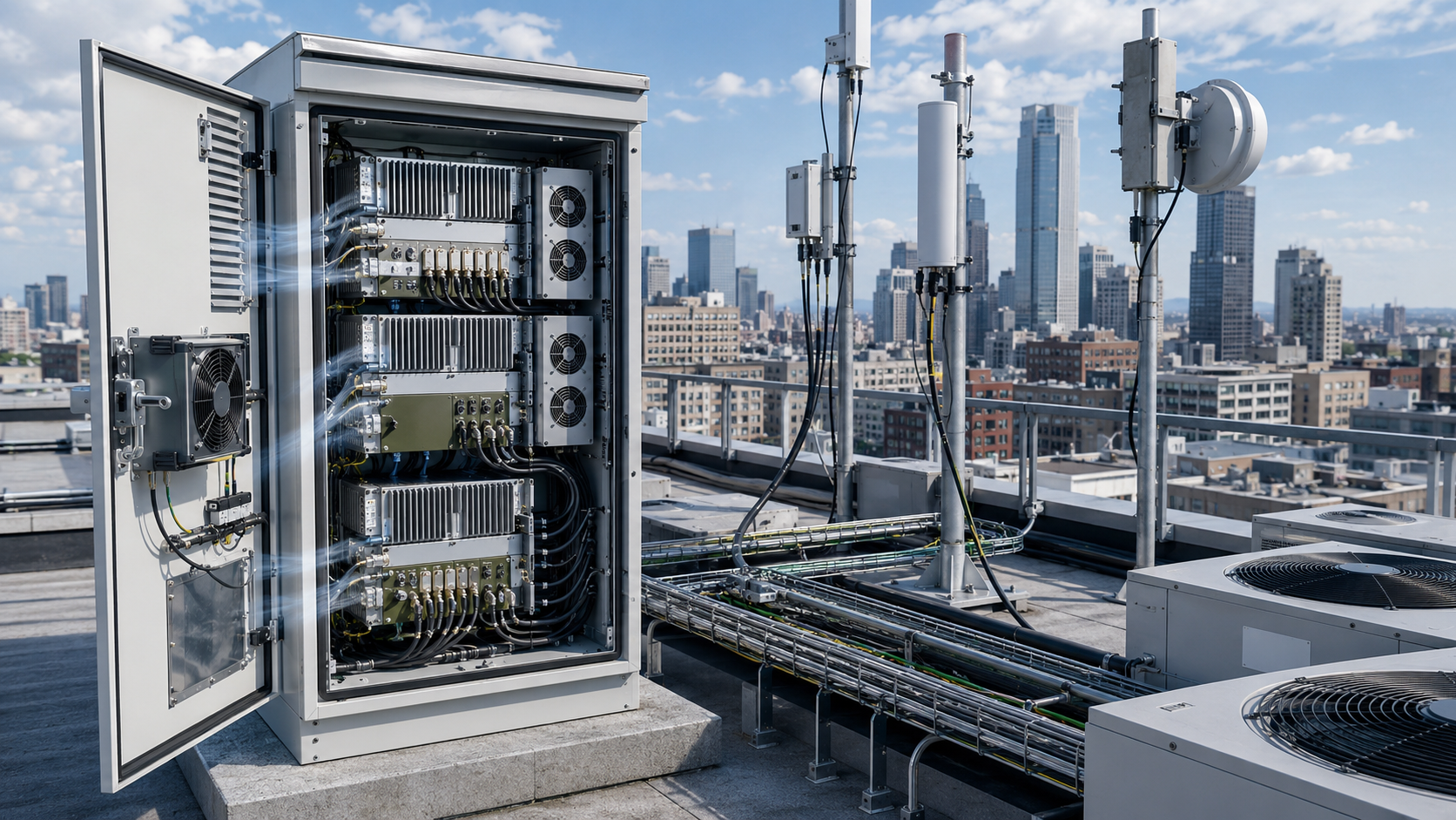
A compact RF PA module can look ideal when enclosure space is limited, yet RF PA cabinet size is not determined by the module outline alone. If the required operating point creates a higher electrical and thermal burden, the cabinet may need more heatsink capacity, airflow clearance, module spacing, or another cooling path before the required RF output can be sustained.
Efficiency matters only after the metric and electrical boundary are defined. PAE, drain efficiency, and module DC-to-RF efficiency are not interchangeable thermal inputs, and an undefined efficiency percentage is not enough to size a cabinet.
The real question is not simply whether the PA is physically small. It is whether the complete cabinet can reject the required heat while preserving cooling, RF/DC integration, service access, and hot-state operating margin inside the available envelope.
1. Why Can a Compact RF PA Still Need a Larger Cabinet?
The PA module is only one element inside a C-UAS RF cabinet.
A smaller amplifier can reduce the space occupied by the RF stage, but the enclosure must still accommodate:
- Heatsink or cold-plate requirements
- Airflow and module spacing
- RF filters, combiners, and switching
- DC distribution and control hardware
- Cable and connector access
- Service and environmental clearances
This is why two PA modules with similar mechanical dimensions can lead to different cabinet envelopes.
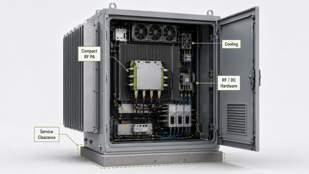
For a defined module DC-to-RF efficiency boundary, lower efficiency at the same Pout means more DC input power is required at that boundary.
That higher DC demand increases the electrical power the cabinet must support. The actual PA dissipation must then be determined from the complete RF and DC power balance rather than inferred from the efficiency percentage alone.
Higher dissipation increases the required heat-rejection capacity, but it does not translate directly into cabinet volume. Depending on the cooling architecture, the design may need a larger heatsink, more airflow clearance, wider spacing, liquid cooling, or another thermal solution.
The engineering conclusion is simple:
A smaller PA can support a smaller cabinet only when the complete thermal and integration boundary also fits inside that smaller enclosure.
2. Which Efficiency Boundary Should Cabinet Sizing Use?
Before efficiency is used in cabinet planning, engineers must define what the percentage represents.
Common metrics include:
- PAE
- Drain efficiency
- Module DC-to-RF efficiency
- A project-defined system efficiency
These values cannot be substituted for one another.
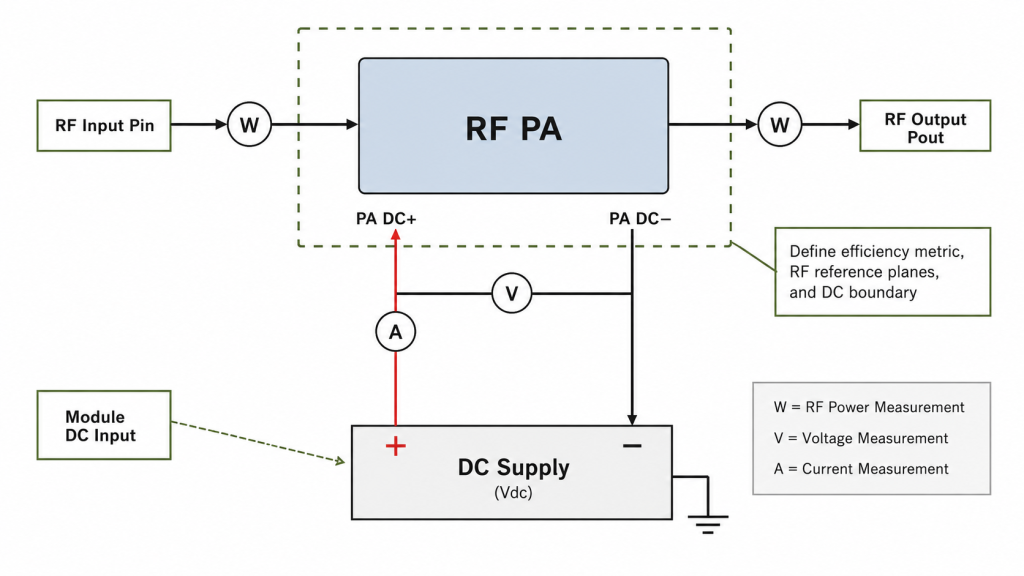
For a module DC-to-RF efficiency defined as:
Efficiency = Pout / Pdc
the required module DC input is:
Pdc = Pout / Efficiency
Under a steady DC operating condition:
Pdc = Vdc × Idc
If Vdc and Idc are measured at the module terminals, this represents module DC input power. It should not automatically be treated as final-stage drain power.
PAE uses a different relationship:
PAE (%) = ((Pout − Pin) / Pdc) × 100%
Pin and Pout must be expressed in linear power units such as watts, and their RF reference planes must be defined with applicable path corrections included.
When actual PA dissipation is needed, the complete power balance should include both RF and DC input power:
Pdiss = Pdc + Pin − Pout
This is why an undefined statement such as:
Efficiency = 35%
is not enough for cabinet thermal design.
Engineers first need to know which metric is being used and where Pin, Pout, Vdc, and Idc were measured. The detailed heat-load calculation is covered separately in RF PA heat load.
An Illustrative 200 W Example
Assume a module DC-to-RF efficiency defined as Pout/Pdc at the module DC-input boundary.
At the same 200 W RF output:
- At 40% module efficiency, Pdc = 500 W
- At 25% module efficiency, Pdc = 800 W
The lower-efficiency operating point therefore requires 300 W more DC input power at the same Pout.
That difference matters to cabinet design because the power system and cooling architecture must support the higher electrical demand.
However, the 300 W difference in Pdc should not automatically be described as the exact difference in PA heat dissipation. Exact dissipation should use Pin, Pout, Pdc, and the defined RF/DC boundaries.
The example proves one specific point:
Lower conversion efficiency can substantially increase the DC input requirement that the cabinet must support.
3. How Does PA Dissipation Change Cooling Space?
PA dissipation increases the thermal capacity required from the cooling system.
In an air-cooled enclosure, this may require:
- More heatsink area
- Higher airflow through the intended thermal path
- Greater inlet and outlet clearance
- More separation between heat-producing modules
In a liquid-cooled design, the same burden may instead affect cold-plate capacity, coolant routing, manifold space, and heat-exchanger requirements.
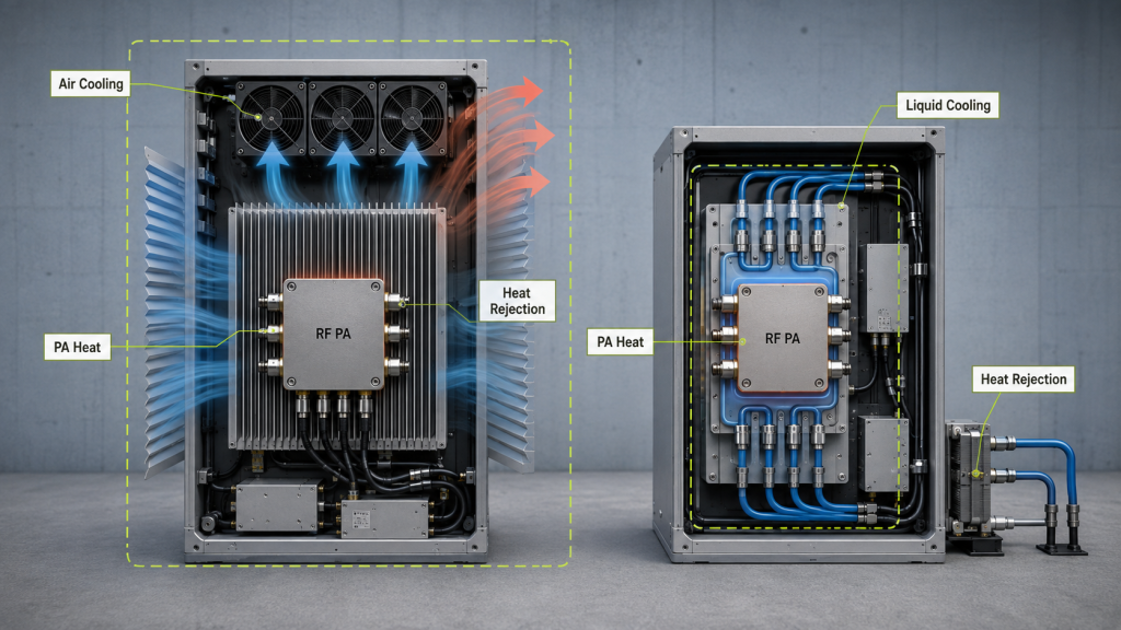
More heat therefore does not automatically mean a larger cabinet. A higher-capacity cooling architecture may reject more heat within the same volume, while a poor airflow path can require a larger enclosure even at lower dissipation.
The external heatsink should therefore be selected from the PA thermal boundary, not from module dimensions alone. Where that interface is the main design question, RF PA heatsink design should be reviewed separately.
The same applies to airflow. A fan’s free-air rating does not prove that the required airflow reaches the PA once filters, vents, heatsinks, cables, and partitions are installed. Detailed verification belongs in the separate RF PA cabinet airflow review.
For this page, the cabinet-sizing question is narrower:
What cooling capacity and physical clearance must the enclosure reserve for the PA’s defined thermal burden?
4. What Other Constraints Can Override PA Module Size?
PA dissipation is only one dimensioning input.
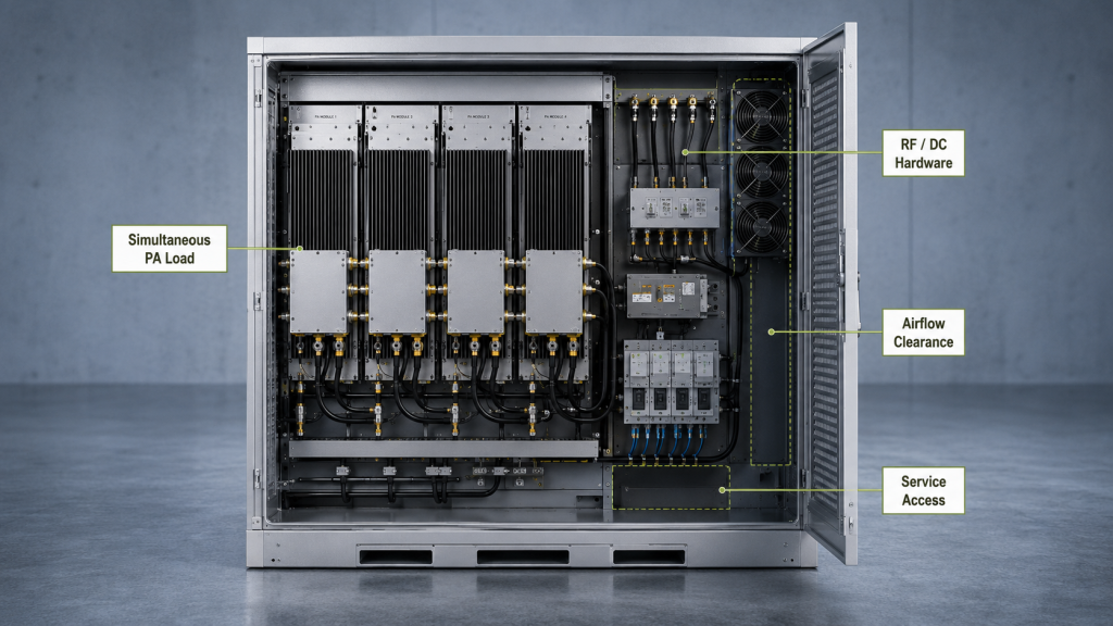
| Cabinet input | Why it affects the enclosure | What should be defined |
|---|---|---|
| PA dissipation | Sets part of the heat-rejection requirement | Calculation method, RF/DC boundaries, operating point |
| Simultaneous PA channels | Sets combined thermal and DC load | Required active-channel combination |
| Cooling architecture | Changes hardware and clearance requirements | Air, liquid, cold plate, ducting, or other method |
| Airflow clearance | Prevents recirculation and restriction | Inlet, outlet, filter, fan, and heatsink geometry |
| Environmental boundary | Changes available thermal margin | Ambient, solar load, sealing, filtration |
| RF/DC hardware | Occupies non-PA volume | Filters, combiners, supplies, control hardware |
| Service access | Limits packing density | Cable, connector, replacement, and maintenance clearance |
Simultaneous Load
A single PA should not be the sole sizing reference if several channels can operate together.
The relevant cabinet burden depends on the actual simultaneous combination and its frequency, Pout, efficiency boundary, duty condition, and thermal state.
Airflow and Spacing
Packing modules closer together can reduce mechanical volume while restricting airflow, increasing recirculation, or heating adjacent hardware.
The smallest possible mechanical arrangement is therefore not automatically the smallest acceptable cabinet.
Environment and Other Hardware
Outdoor or rooftop C-UAS installations may also face high ambient temperature, solar load, filtration, sealing, or restricted vent area.
At the same time, filters, combiners, DC supplies, control hardware, telemetry, and cabling may occupy more volume than the PA itself.
Efficiency should therefore remain one cabinet-sizing input, not the sole determinant.
5. What Evidence Proves the Cabinet Envelope Is Large Enough?
A CAD model showing that every component fits is not enough.
The completed enclosure should be evaluated under operating and mechanical conditions representative of the intended installation.
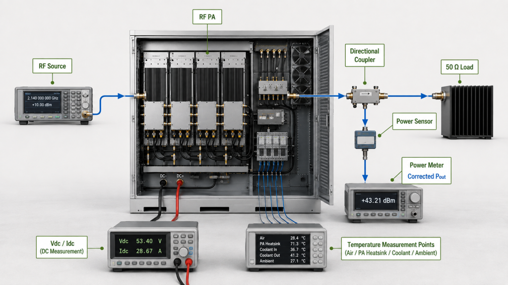
Useful evidence can include:
- Frequency and required Pout
- Simultaneous active channels
- Efficiency metric and RF/DC boundaries
- PA dissipation calculation or measurement basis
- Module-terminal Vdc and Idc where relevant
- Cooling and ambient condition
- Temperature measurement points
- Load or VSWR condition
- Operating duration
- Protection status
- Final enclosure configuration and airflow restrictions
The DC data must match the selected efficiency metric. Module-terminal Vdc and Idc should not automatically replace drain-supply data when drain efficiency is being evaluated.
Use a Production-Representative Enclosure
Final verification should reproduce the real cabinet configuration as closely as practical, including normal doors or panels, filters, vents, fans, cable routing, module spacing, partitions, and other airflow restrictions.
A result obtained with the enclosure open or with production airflow restrictions removed should not automatically be treated as final-cabinet acceptance evidence.
The acceptance plan should also define in advance:
- Test duration or operating profile
- Temperature limits or allowable drift
- RF-output limits where applicable
- DC boundaries
- Cooling and ambient conditions
- Load condition
- Protection criteria
This is more useful than simply requiring that temperature and output remain “stable.”
Separate PA Evidence From Cabinet Evidence
PA-level and cabinet-level evidence are not the same responsibility.
The PA supplier can verify the module’s RF, DC, efficiency, thermal, cooling-interface, and protection boundaries under an agreed PA test condition.
The final cabinet may also contain customer-selected fans, filters, supplies, RF hardware, cabling, and other heat sources.
Final-enclosure acceptance should therefore be performed by the party responsible for the complete cabinet integration unless final-cabinet design and testing are explicitly included in the PA supplier’s scope.
6. What Should the RFQ Define Before Cabinet Size Is Locked?
Cabinet dimensions should not be frozen before the PA operating and thermal boundaries are understood.
| RFQ item | Buyer / Integrator should define | PA supplier should confirm |
|---|---|---|
| Target frequency | Required operating points or range | Test coverage at required frequencies |
| Required Pout | Continuous or project-defined RF output | Measured Pout at defined output plane |
| Efficiency | Required metric or acceptance method | Metric, formula, RF planes, DC boundary |
| DC power | Available voltage and current budget | Measured voltage/current at required PA boundary |
| PA dissipation | Cabinet thermal constraints | Dissipation value or estimate, method, boundaries, operating point |
| Simultaneous operation | Required active-channel combination | Per-module data and combined evidence when in scope |
| Cabinet envelope | Available dimensions and restrictions | PA mechanical and cooling-interface requirements |
| Environment | Ambient, sealing, filtration, solar/site limits | PA test conditions used for verification |
| Acceptance | Required PA-level and cabinet-level criteria | PA-level evidence; final-cabinet evidence only when in scope |
The customer should not have to guess the PA’s full-load current, dissipation, or cooling-interface requirement.
The PA supplier provides those module-level inputs under defined operating conditions. The system integrator then combines them with other cabinet heat sources, airflow restrictions, DC distribution, RF hardware, cable routing, and environmental conditions.
A cabinet should therefore not be selected from:
- PA dimensions alone
- Rated Pout
- One undefined efficiency percentage
- Fan CFM alone
- One room-temperature bench result
Once those boundaries are defined, RF SKYPOWER’s Custom RF Power Amplifier Modules provide an engineering starting point for reviewing frequency, Pout, DC demand, efficiency, cooling interface, control, protection, and mechanical integration before the enclosure is finalized.
FAQ
Does a smaller RF PA always allow a smaller cabinet?
No.
A smaller PA reduces the module footprint, but the enclosure still has to provide cooling capacity, RF/DC hardware space, cable routing, service access, and environmental margin.
A physically smaller PA can therefore still require a larger total integration envelope.
Does higher RF PA efficiency always mean a smaller cabinet?
No.
At the same Pout and a defined module DC-to-RF boundary, higher efficiency reduces the required DC input power.
That can reduce the PA’s thermal burden, but actual dissipation should be determined from the complete RF and DC power balance.
Cabinet size also depends on cooling architecture, simultaneous channels, environmental conditions, airflow restrictions, service clearance, and other hardware.
What evidence should prove a compact RF PA cabinet is acceptable?
For the PA, the evidence should define frequency, Pout, efficiency metric, RF/DC boundaries, DC demand, dissipation, cooling-interface condition, temperature evidence, and protection behavior.
For the complete cabinet, the responsible integrator should also verify the production-representative enclosure with the required simultaneous load, cooling configuration, airflow restrictions, environment, operating duration, and acceptance limits.
The key question is not whether the hardware fits. It is whether the integrated cabinet can sustain the required operating condition.
Conclusion
RF PA efficiency can affect C-UAS cabinet size, but efficiency alone does not determine the enclosure dimensions.
For a defined module DC-to-RF efficiency boundary, lower efficiency at the same Pout requires more DC input power. That higher electrical demand can increase the cabinet thermal burden, while the actual PA dissipation should be determined from the complete RF and DC power balance.
The resulting thermal requirement may affect heatsink capacity, airflow clearance, module spacing, liquid-cooling hardware, or another cooling solution. Final cabinet size also depends on simultaneous channel load, environmental conditions, RF/DC hardware, service access, and the production-representative enclosure configuration.
PA-level evidence and final-cabinet evidence should remain separate unless the PA supplier is explicitly responsible for the complete enclosure.
Before RFQ, send RF SKYPOWER your target frequencies, required Pout, efficiency metric, available DC budget, simultaneous-channel requirement, cabinet limits, cooling architecture, environmental conditions, load or VSWR requirement, operating duration, protection criteria, and required PA-level evidence.
These inputs allow the PA’s electrical and thermal contribution to be defined before the cabinet integrator locks the final enclosure dimensions.