When Should You Choose 30-512MHz RF Power Amplifier Modules?
June 29, 2026
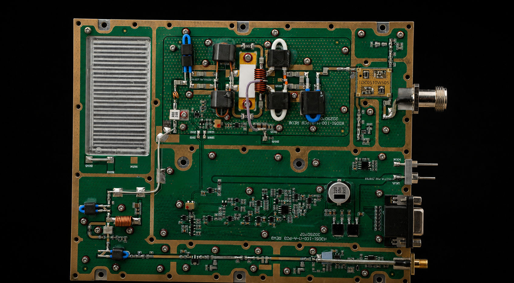
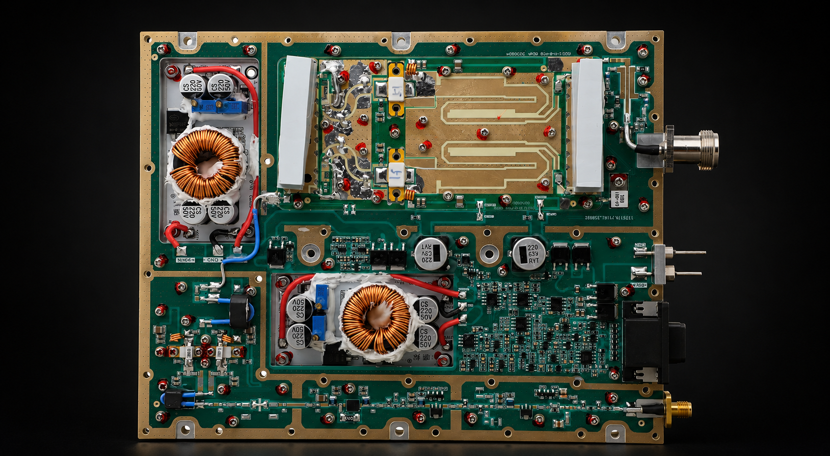
30-512MHz RF Power Amplifier Modules give engineers a flexible low-frequency route for projects that need RF output across VHF and part of the UHF region. With multiple power classes available, this family can support projects ranging from moderate-output RF chains to higher-power multi-channel platforms while keeping frequency, DC, cooling, and control requirements inside one clear product route.
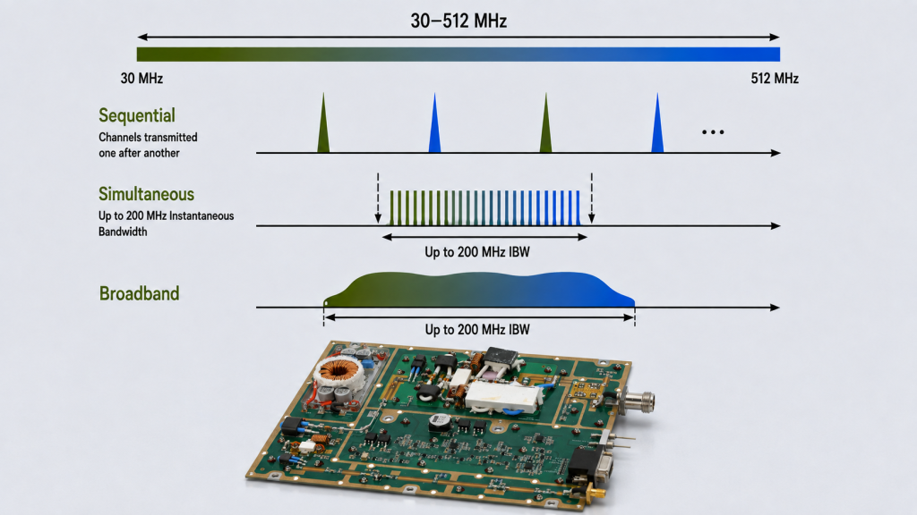
The current HZ30512 series combines a 30–512MHz operating range with 200MHz instantaneous bandwidth, giving customers a practical starting point for frequency-agile and broadband low-band requirements.
The fastest way to choose the right module is to define which frequencies must operate, whether they are used sequentially or simultaneously, what RF output is required, and what bandwidth the signal needs. From there, the 30W, 50W, 100W, 150W, and 200W options can be matched to the actual RF chain instead of selected by wattage alone.
1. Why Is 30–512MHz a Flexible Low-Band RF PA Route?
The value of the 30–512MHz route is its ability to cover a broad lower-frequency operating region without forcing every project into one fixed frequency point.
That makes it useful for systems that may need:
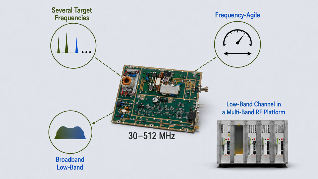
Several defined VHF / lower-UHF operating frequencies
Frequency-agile RF output
Broadband low-frequency signals
Multiple low-band channels inside a larger RF platform
Future frequency flexibility within the supported route
One product family with several output-power classes
The key is matching the RF requirement to the right configuration.
Four items make that process much easier:
Operating frequency range: where the selected module is designed to operate.
Instantaneous bandwidth: how much bandwidth the quoted configuration can support at one time.
Target frequencies: the actual frequencies or sub-bands the project will use.
Operating mode: whether several frequencies are used sequentially or must operate simultaneously.
The current HZ30512 series page lists a 30–512MHz operating route with 200MHz instantaneous bandwidth. For RFQ, customers can simply provide the frequencies, channel arrangement, and signal-bandwidth requirement so the exact configuration can be matched to the application.
For projects using several discrete frequencies one after another, the main selection focus may be target-point output and gain.
For projects using multiple frequencies simultaneously, occupied bandwidth and channel arrangement become equally important.
For projects that need broad frequency agility, the 30–512MHz route provides a useful platform from which the final RF configuration can be defined.
This flexibility is one of the main reasons the series is useful as a low-band RF PA route rather than only as a single-frequency amplifier choice.
2. Which Projects Benefit Most from 30–512MHz RF PA Modules?
The 30–512MHz route is especially useful when low-band RF coverage is already part of the system plan.
Instead of choosing a module first and building the system around it, engineers can start from the project frequency map and use the HZ30512 family as the product route when those operating points fall inside 30–512MHz.
Project requirement
Why 30–512MHz is worth reviewing
Next selection step
Several target frequencies inside 30–512MHz
One product route can cover multiple required operating points
Confirm Pout and gain at target frequencies
Broadband low-frequency RF is required
HZ30512 provides a defined wideband low-frequency platform
Confirm required instantaneous bandwidth
Frequencies must change during operation
Wide operating range supports frequency-agile planning
Define switching / control and target points
Low-band channels are part of a multi-band C-UAS cabinet
Provides a dedicated lower-frequency PA route
Confirm simultaneous channels, DC, and cooling
Future low-band expansion is expected
Wider operating flexibility can reduce early frequency lock-in
Reserve RF, DC, thermal, and control margin
For C-UAS and other multi-band RF platforms, this can be particularly useful because the low-band PA does not have to solve the entire RF system.
It can serve as the dedicated 30–512MHz output stage while other PA families handle higher-frequency channels.
That gives system engineers a clean way to divide the frequency plan by RF PA route.
If the broader system frequency plan, Pout requirement, control interface, or duty condition is still being defined, the RF PA selection process can be used before the final module is frozen.
3. How Do You Choose Between 30W, 50W, 100W, 150W, and 200W?
Once the 30–512MHz route is confirmed, the next question is usually power.
The current series gives engineers five practical starting points:
30W
50W
100W
150W
200W
This range makes it possible to match the amplifier more closely to the real RF requirement instead of automatically oversizing the PA.
Power class
Good starting point when
Confirm before final selection
30W
Moderate PA-port output is required and DC / thermal space is valuable
Target-frequency Pout, Pin, gain, current, cooling
50W
Additional output margin is useful while keeping the power system relatively compact
Hot-state Pout, DC demand, gain, load condition
100W
The RF chain needs stronger PA-port output at defined target frequencies
The selection becomes even easier when the required RF result is tied to a reference plane.
If the customer already knows the required PA-port output, that value can be used directly as the main product-selection input.
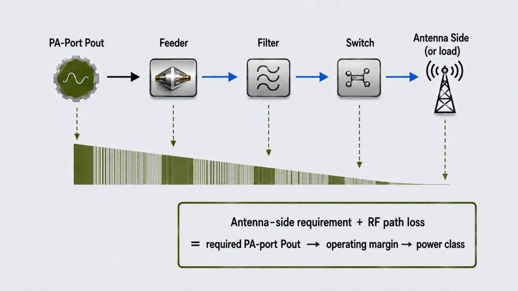
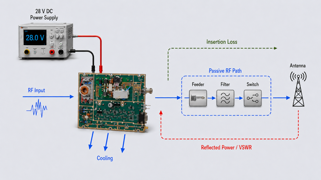
If the requirement is defined at the antenna side, use the downstream RF path to derive the PA output requirement:
Required antenna-side result + downstream RF-path loss → required PA-port Pout → operating margin → power class
This approach helps avoid both under-sizing and unnecessary over-sizing.
For example, a project with a moderate antenna-side requirement and a short, low-loss RF path may be well served by a lower power class. Another project with a longer feeder, additional filters, switches, or greater output margin may benefit from moving to 100W, 150W, or 200W.
The important point is that RF SKYPOWER offers enough power-class choice inside the same 30–512MHz route to let the PA follow the system requirement.
Once the required power class is shortlisted, engineers can review the current HZ30512 module options and available datasheets below.
4. What RF Performance Should You Confirm Before Choosing the Final Module?
Once the frequency route and power class are shortlisted, a few RF measurements help turn the shortlist into a confident product choice.
The useful evidence depends on how the module will actually be used.
Target-Frequency Pout
For projects with defined operating points, ask for Pout at those frequencies.
This makes the data directly relevant to the project instead of relying only on one representative frequency.
If the project requires wider frequency coverage, the test scope can be expanded across the required range.
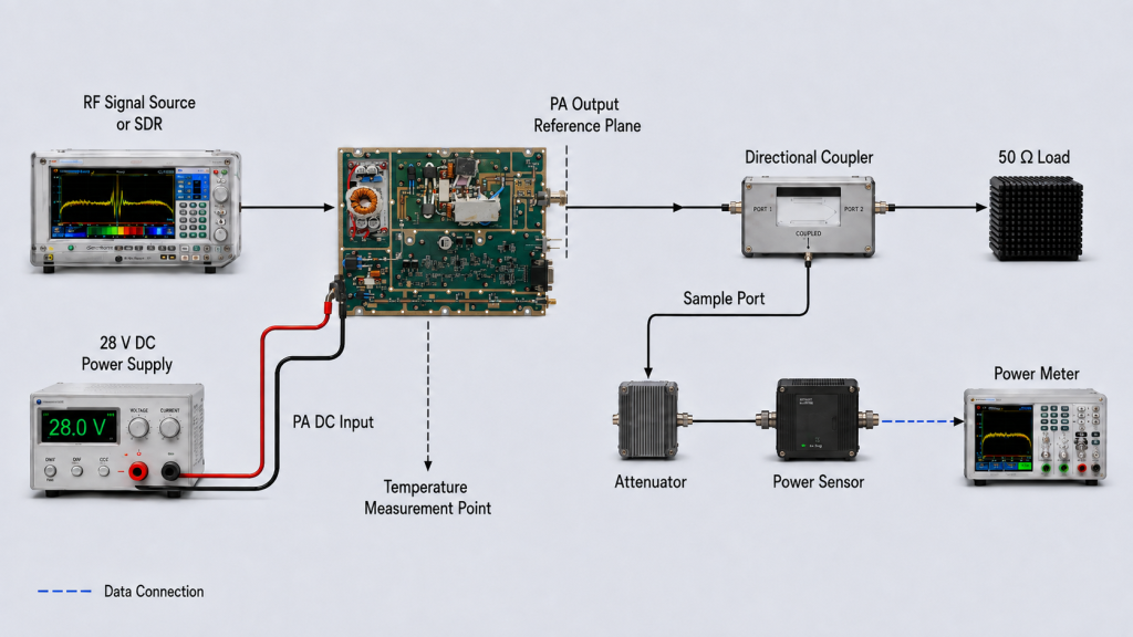
RF Output Reference Plane
The supplier should define where Pout is referenced.
This gives the customer a clear PA-port value that can later be combined with feeder, filter, switch, and antenna-path information.
Any cable, fixture, coupler, attenuator, or adapter correction included in the reported value should also be identified.
RF Input Drive
Pin and gain matter because the PA must work with the real signal source.
When an SDR or other exciter is used, confirming the required drive condition helps ensure that the signal source and amplifier are matched as one RF chain.
Gain and Gain Flatness
Where several frequencies are used, gain flatness helps engineers understand how consistent the PA behavior is across the required points.
This is especially useful for frequency-agile or multi-point systems where the same signal source must drive several operating frequencies.
Hot-State Performance
For CW or long-duty applications, hot-state RF data gives the buyer a more useful view of sustained performance.
The test can be matched to the project’s:
Duty condition
Cooling arrangement
Load
Operating duration
Acceptance limits
The goal is simple: request the evidence that helps select the module you actually intend to operate.
5. How Do Antenna, Feeder, VSWR, DC, and Cooling Work with the PA Choice?
One advantage of defining the PA module clearly is that the rest of the RF chain becomes easier to design around it.
The PA can first be characterized at a defined module-level RF, DC, load, and cooling boundary. The system integrator can then use that data when completing the feeder, antenna, cabinet, and power-system design.
Feeder and Antenna-Side Power
For a passive downstream RF path, a useful first-order power-budget relationship is:
Pantenna (dBm) ≈ Pout,PA (dBm) − Lpath (dB)
where Lpath represents insertion loss between the defined PA output reference plane and the antenna-side reference plane.
Depending on the system, that path may include:
Feeder cable
Connectors
Filters
RF switches
Combiners
Other passive components
This is why PA-port Pout and antenna-side requirement work well together during selection.
When feeder loss is important, the RF PA feeder path can be reviewed separately.
Antenna and VSWR
The 30–512MHz route should also be matched to the real antenna environment.
Useful RFQ information includes:
Antenna operating range
Feeder length
Expected installed VSWR
Connector type
Reflected-power requirement
Installation / grounding condition
Cabinet-to-antenna distance
With those inputs, the module-side load and protection requirements can be reviewed together with the installed RF path.
DC Power
Customers can provide the available DC voltage and current budget.
RF SKYPOWER can then match the chosen module and operating point to the expected DC requirement under the agreed:
Frequency
Pout
RF drive
Duty condition
Cooling condition
Thermal state
This is more useful than asking the customer to estimate PA current before a module has been selected.
Cooling
The same principle applies to cooling.
Rather than estimating heat only from the wattage label, the selected module can be reviewed against its actual operating point, efficiency, DC demand, cooling interface, and duty condition.
That lets the customer choose the 30W–200W class with a clearer view of the final cabinet and power-system requirements.
6. How Does 30–512MHz Fit into a Wider RF PA Product Plan?
The 30–512MHz family is the natural low-band route within RF SKYPOWER’s wider RF PA portfolio. It gives engineers a defined starting point when the required operating frequencies remain inside the VHF and lower-UHF region.
When a project also includes higher-frequency channels, the complete frequency map should be divided into practical PA sections rather than forced into one amplifier. The comparison below shows where the 30–512MHz family fits and which wider RF PA route to review when the required coverage extends beyond it.
Compare RF PA Routes by Frequency Coverage
Keep 30–512MHz as the low-band route, or move to a wider family when the project frequency map extends beyond this range.
Start here when the required operating points remain within the VHF and lower-UHF region. Select the final module by target frequencies, bandwidth, PA-port output, duty condition, DC demand, and cooling boundary.
Covers the UHF region from 300MHz upward and extends into the lower L-band to 1.2GHz. Review this route for projects that need several UHF operating points or a frequency plan crossing the UHF-to-L-band boundary.
Covers UHF and continues through most of the L-band to 1.7GHz. It is a practical route when one PA family must support both sub-1GHz channels and additional L-band operating points.
Spans UHF, the full L-band, and the lower part of the S-band to 2.7GHz. Consider it when the RF plan crosses multiple band boundaries and requires one broad lower-to-mid-frequency PA route.
Covers the S-band from 2–4GHz and extends into the lower C-band from 4–6GHz. Route higher-frequency communication, data-link, test, or multi-band RF requirements here after confirming feeder loss, antenna match, and target-frequency output.
Need a different frequency boundary or interface? Send the required range, Pout, bandwidth, voltage, cooling, connector, control, and test-evidence requirements through the custom RF PA RFQ.
For a project centered on low-band frequencies, 30–512MHz remains the primary route. In a multi-band platform, it can serve as the dedicated low-frequency PA section while the appropriate wider-band families handle the remaining channels.
The final choice should still follow the engineering requirement: define the frequency map first, select the matching PA family for each section, and then confirm the required power class, bandwidth, RF input, DC supply, cooling, control, and test evidence within that family.
Customers who want to compare the complete portfolio can also review the Wideband RF Power Amplifier Modules range before finalizing the system frequency plan.
7. What Should You Send for a Faster 30–512MHz RFQ?
A clear RFQ helps RF SKYPOWER move directly from “we need a 30–512MHz PA” to an actual module recommendation.
Instead of sending only:
Please quote a 100W 30–512MHz amplifier.
include the engineering inputs that determine the final configuration.
PA-port reference plane and module-side load requirement
VSWR / load
Expected load environment and acceptance boundary
Applicable protection / reflected-power behavior
Control
Enable, monitoring, gain adjustment, alarm, or interface needs
Available control options for the quoted configuration
Evidence
Required frequencies, test duration, report, traceability
Test evidence available for the selected module and agreed scope
With this information, the engineering team can quickly determine:
Which HZ30512 configuration fits the frequency requirement
Whether the project uses discrete, simultaneous, or broadband RF operation
Which power class best fits the required output
How much PA-port Pout is needed
Whether the available DC and cooling system are appropriate
What load / VSWR conditions should be included
Which measurements should accompany the quotation or acceptance package
This turns the RFQ into a product-selection process instead of a simple price request.
FAQ
What makes 30–512MHz RF PA modules attractive for low-band projects?
They combine a broad lower-frequency operating route with multiple available power classes, giving engineers flexibility to match frequency, Pout, DC, cooling, and system requirements inside one product family.
They are particularly useful when a project needs several VHF / lower-UHF operating points, frequency agility, broadband low-band signals, or a dedicated low-frequency PA section inside a larger multi-band system.
How should I choose between 30W, 50W, 100W, 150W, and 200W?
Start from the required RF result.
If the requirement is at the antenna side, include downstream RF-path loss to derive the PA-port Pout. Then add the required operating margin and choose the closest appropriate power class.
Frequency, duty condition, DC budget, cooling, and VSWR should then be confirmed for that configuration.
What information helps RF SKYPOWER recommend the correct module?
The most useful inputs are target frequencies, sequential or simultaneous operation, required bandwidth, Pout and reference plane, available RF drive, duty cycle, DC supply, cooling method, feeder / antenna path, VSWR boundary, control requirements, and required test evidence.
The more clearly these conditions are defined, the faster the 30–512MHz series can be narrowed to the appropriate configuration and power class.
Conclusion
A 30–512MHz RF PA module is a strong choice when a project needs flexible VHF / lower-UHF RF output and wants several power classes available inside one low-band product route.
The HZ30512 family gives engineers a practical way to start with the required frequencies and then match the PA to the project’s bandwidth, RF output, DC supply, cooling, antenna path, and control requirements.
Define the real frequency plan first. Then determine whether the frequencies operate sequentially or simultaneously, establish the required RF reference plane, calculate any downstream RF-path requirement, and choose the appropriate 30W, 50W, 100W, 150W, or 200W class.
From there, target-frequency RF data, DC demand, cooling, VSWR behavior, and test evidence can be matched to the selected configuration.
For a 30–512MHz RFQ, send RF SKYPOWER your target frequencies, required Pout, RF reference plane, bandwidth requirement, RF input drive, duty cycle, available DC supply, cooling method, feeder and antenna information, VSWR boundary, control requirements, and required test evidence.
RF SKYPOWER is a Source Factory engineering precision RF modules, antennas, SDR signal sources, and detection systems built exclusively for defense, security, and critical infrastructure applications.
When R&D, manufacturing, and testing happen under one roof, you get unmatched quality control and supply chain stability.