











RF PA datasheet efficiency looks easy to compare. Two suppliers may both publish 45%, so the higher or more familiar number can seem like the safer choice for current draw, thermal design, or power-supply sizing.
The problem is that an efficiency percentage can be technically valid while the comparison is still invalid. A datasheet may not show enough of the measurement condition to prove that two apparently similar numbers describe the same operating point.
Before efficiency influences the shortlist, what exactly must be matched—and what evidence proves that the two numbers are genuinely comparable?
1. What Does RF PA Datasheet Efficiency Actually Prove?
An efficiency percentage proves only the result inside the measurement and electrical boundary used to calculate it.
The first question is therefore not:
“Is 45% good?”
It is:
“45% of what, measured where, and under which operating condition?”
Common RF PA efficiency terms do not describe the same boundary.
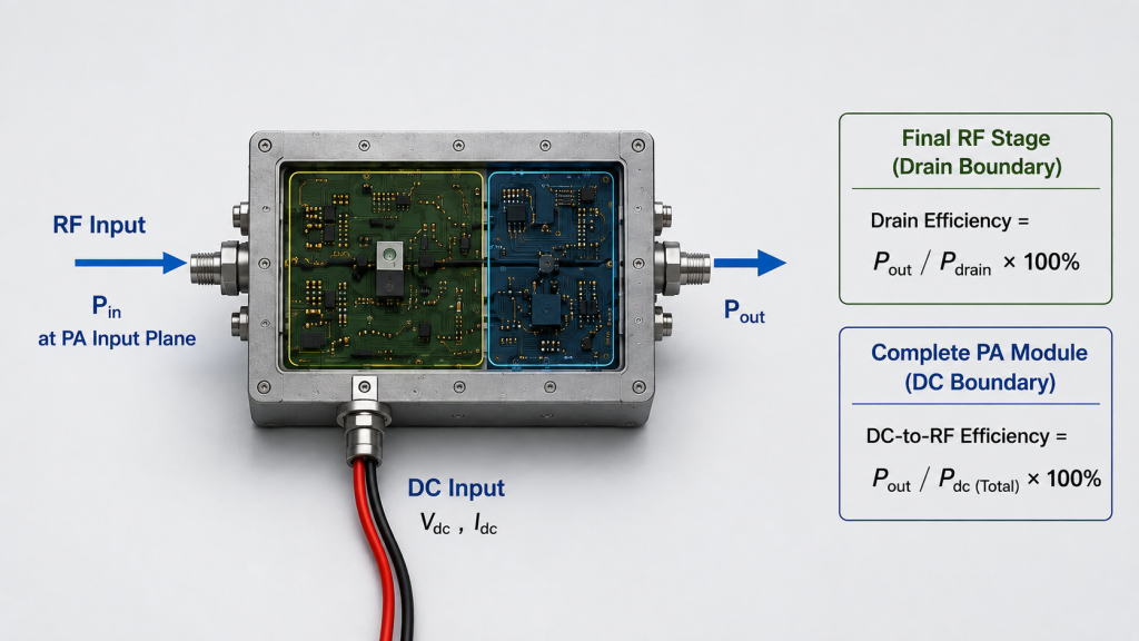
For example:
- Drain efficiency compares RF output power with the DC drain power supplied to the RF power stage or stages included in the stated measurement boundary. It should not be used as another name for complete module DC-to-RF efficiency.
- Power-added efficiency (PAE) accounts for both RF output power and RF input power relative to the defined DC power consumed by the DUT.
- Module DC-to-RF efficiency can use the complete PA-module DC input as its denominator, including whatever electrical loads are explicitly included in that module boundary.
- A supplier may also publish a typical, peak, measured, minimum, or guaranteed value.
For a defined RF power-stage drain boundary:
Drain Efficiency = Pout / Pdrain × 100%
For a defined DUT and DC boundary:
PAE = (Pout − Pin) / PDC × 100%
If one drain supply is used:
Pdrain = VDD × IDD
If several drain rails or RF power stages are included in the stated boundary, their applicable DC power must be included consistently rather than assuming one VDD × IDD term represents the whole measurement.
PAE and drain efficiency should therefore not be treated as interchangeable percentages. A module-level efficiency value should also not be ranked directly against a final-stage drain-efficiency result unless the electrical boundaries are aligned first.
The distinction between PAE and drain efficiency becomes especially important when suppliers use different metric names, different DUT boundaries, or different DC denominators.
A datasheet is still useful at this stage. It identifies the rated frequency range, nominal supply condition, output target, gain, protection features, and the efficiency claim that requires verification.
What it does not automatically prove is the current draw, thermal burden, or performance of the complete installed RF system.
2. Which Test Conditions Must Match Before You Trust the Number?
Even two results labelled with the same efficiency metric may not be directly comparable.
The operating point and measurement definition behind each result must be checked.
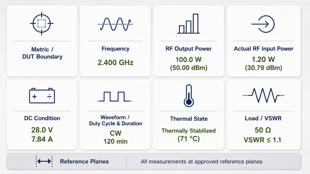
Efficiency metric and DUT boundary
Confirm whether the value represents:
- PAE;
- drain efficiency;
- module DC-to-RF efficiency;
- or another clearly defined metric.
Then confirm what the DUT includes.
A final transistor stage, multi-stage RF power section, complete PA module, amplifier assembly, and complete cabinet do not necessarily have the same DC boundary.
If two suppliers use different electrical boundaries, the percentages should not be ranked until the difference is understood.
Frequency
Efficiency can change across a frequency range as matching, gain, available output, current draw, and operating margin change.
A center-frequency value should not automatically represent a project operating near a band edge.
If efficiency affects the selection decision, request measurements at the actual required frequency points rather than relying on one favorable datasheet value.
For wideband comparisons, review RF PA efficiency across frequency bands separately from the headline percentage.
RF input and output power
Efficiency belongs to a specific operating point.
The report should identify:
- actual Pin at the PA input reference plane;
- Pout at the defined PA output reference plane;
- whether Pout represents rated, backed-off, compressed, or another defined operating condition;
- whether Pin is fixed or adjusted at each frequency.
Do not infer actual RF input power from a signal-generator, exciter, or SDR setting alone.
Loss or gain between the source and PA input can change what actually reaches the amplifier. Where Pin affects the efficiency comparison, the actual RF PA input power should be measured or calibrated at the agreed reference plane.
The meaning of Pout must also remain consistent.
Under a matched load, PA-port output power may be straightforward to define. Under mismatch or a real antenna condition, however, the report must state whether Pout means:
- forward power at the PA output port;
- net power delivered after reflected power is accounted for;
- or another explicitly defined RF power quantity.
Efficiency values calculated with different Pout definitions should not be ranked directly.
DC voltage and current
Record Vdc and Idc at the electrical boundary used in the efficiency calculation.
For module-level integration, voltage at the PA module terminals under load can be more useful than an upstream power-supply setting if cables, connectors, relays, fuses, or distribution hardware create voltage drop between the supply and module.
A percentage without its corresponding DC boundary cannot reliably support power-path sizing.
Waveform, duty cycle, and operating time
A short measurement and a continuous operating condition are not the same acceptance boundary.
The efficiency result should identify:
- waveform;
- duty cycle;
- operating duration;
- observation interval;
- and, where relevant, the averaging or gating method.
For pulsed or modulated tests, Pin, Pout, and DC power should use a consistent averaging or gating interval so the reported efficiency represents the same observation window.
For continuous operation, distinguish:
- cold state;
- thermal transition;
- stabilized hot-state observation.
A cold result can be valid for the instant when it was measured without proving what the amplifier will do after temperature, current, and RF output have stabilized.
Where long-duty operation matters, RF PA efficiency during continuous CW operation should be checked under the intended electrical and thermal boundary.
Load and thermal condition
A dummy load, real antenna path, open bench, and closed cabinet may expose different operating behavior.
The efficiency equation itself may not change, but the measured Pin, Pout, Vdc, Idc, temperature, and protection state can change when RF or thermal conditions change.
The test should therefore state:
- load condition;
- agreed VSWR boundary where applicable;
- Pout definition under mismatch;
- cooling method;
- ambient condition;
- thermal state;
- and whether protection or derating was active.
When Two Efficiency Numbers Are Not Comparable
| Comparison condition | Why a mismatch matters | What to request |
|---|---|---|
| Efficiency metric | PAE, drain efficiency, and module efficiency use different definitions | Metric name and equation |
| DUT / DC boundary | Different included electrical loads change the denominator | Defined DUT and electrical boundary |
| Frequency | Performance may vary across the band | Data at required frequency points |
| Pout | Rated, backed-off, compressed, or differently defined output conditions can change efficiency | Pout value and operating state |
| Pout under mismatch | Forward power and net delivered power are not the same quantity | Explicit Pout definition |
| Pin | PAE and amplifier operating state depend on actual drive | Pin at the PA input reference plane |
| Vdc / Idc | DC conditions determine the electrical burden | Voltage and current at the defined boundary |
| Waveform / duty cycle | Average RF and DC power can depend on observation method | Signal type, duty cycle, and averaging or gating interval |
| Thermal state | Cold and stabilized operation may differ | Hot-state data and stabilization criteria |
| Load / VSWR | RF loading can affect output, current, and protection behavior | Defined load / VSWR condition |
| Reference plane | Different measurement points can change reported RF power | Pin and Pout reference planes |
If a material condition differs, the efficiency percentages should not be treated as equivalent measurements.
3. Can Two Supplier Efficiency Claims Be Compared Directly?
Only after the relevant measurement boundaries are aligned.
Suppose Supplier A and Supplier B both publish 45% efficiency.
That does not yet prove equal electrical performance.
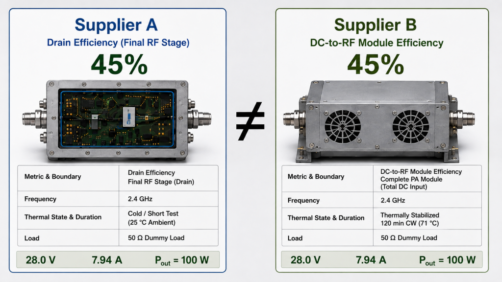
Supplier A might be quoting:
- final-stage drain efficiency;
- at one center-frequency point;
- at rated output;
- with one defined drain supply;
- on an open bench;
- during a short measurement interval.
Supplier B might be quoting:
- complete module DC-to-RF efficiency;
- at a project-specific frequency;
- using total module current;
- after thermal stabilization;
- under a different load condition.
The percentages look identical, but the evidence is answering different questions.
The reverse can also happen.
A supplier with a lower published percentage may be reporting a stricter module-level or hot-state boundary, while a supplier with a higher percentage may be quoting a narrower or more favorable operating condition.
This is why the shortlist should not be created by sorting datasheet percentages from highest to lowest.
A fair comparison should first align:
- efficiency definition;
- DUT and DC boundary;
- Pin and Pout reference planes;
- Pout definition where reflected power is relevant;
- required frequency;
- target RF output;
- actual RF input drive;
- Vdc and Idc;
- waveform and duty cycle;
- averaging or gating interval where required;
- load or VSWR boundary;
- cooling and thermal state;
- measurement duration;
- reporting method.
Only then does the percentage become useful for ranking.
When comparing RF Power Amplifier Modules, use the published efficiency value for screening only until the metric, operating point, DC boundary, and RF measurement definition are aligned.
Do not use efficiency alone to predict heat
A higher efficiency can reduce dissipated power when the compared results use the same relevant boundary and output condition.
But the percentage alone does not define complete cabinet heat load.
The thermal decision may also depend on:
- RF output;
- Pin;
- total module DC consumption;
- auxiliary electrical loads;
- cooling hardware;
- airflow;
- ambient temperature;
- simultaneous operating channels;
- and the applicable duty condition.
If the purpose of the review is heatsink, fan, or cabinet sizing, calculate RF PA heat load from efficiency using the correct module or PA boundary rather than treating a headline efficiency percentage as a heat specification.
4. What Evidence Should Replace a Typical Datasheet Percentage?
A datasheet percentage becomes more useful when the engineering team can trace it back to the measured values and test condition.
The evidence does not need to be complicated.
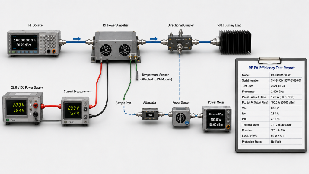
It should be complete enough to answer three questions:
What was measured?
Under which boundary?
Can the result be reproduced at the required operating point?
For an efficiency-sensitive RF PA comparison, request:
- efficiency metric and equation;
- DUT and electrical boundary;
- included drain rails or auxiliary electrical loads;
- target frequency points;
- actual Pin;
- measured Pout;
- Pin and Pout reference planes;
- Pout definition under mismatch where relevant;
- Vdc and Idc;
- waveform and duty cycle;
- averaging or gating interval where applicable;
- test duration;
- load or VSWR condition;
- cooling condition;
- thermal state;
- relevant temperature data;
- protection or derating status;
- whether the value is typical, peak, measured, minimum, or guaranteed;
- measurement uncertainty where it is part of the acceptance requirement;
- model and serial number where per-unit traceability is required.
Datasheet Claim vs Evidence to Request
| Datasheet claim | Evidence to request | What the evidence prevents |
|---|---|---|
| “45% efficiency” | Metric, equation, DUT boundary, Pout, Pin, Vdc, Idc | Undefined percentage comparison |
| “Typical efficiency” | Frequency, output point, thermal state, load, test duration | Favorable-point bias |
| “High efficiency across the band” | Data at required frequency points | Center-frequency assumption |
| “Low current” | Module-terminal Vdc and measured Idc under load | Power-path sizing error |
| “Stable at full power” | Pout, Idc, temperature, and protection status over the required interval | Short-test approval |
| “Suitable for the required load” | Defined load / VSWR boundary and Pout definition | Mismatch between test evidence and field condition |
| “Production test available” | Model/S/N-linked test data where required | Generic evidence used for per-unit acceptance |
The purpose of the evidence package is not to create unnecessary paperwork.
It is to prevent a procurement decision from depending on a number that cannot be reproduced under the project condition.
If the supplier cannot explain the metric, electrical boundary, operating point, RF power definition, and measured values behind the percentage, the efficiency claim should remain a screening reference rather than an acceptance result.
5. How Should RFQs Define the Efficiency Boundary?
“High efficiency required” is not an engineering acceptance criterion.
A stronger RFQ converts the requirement into a measurable boundary.
Before sample approval, define the items that affect the actual decision:
- Efficiency metric: PAE, drain efficiency, module DC-to-RF efficiency, or another agreed metric.
- DUT boundary: which RF stages, DC rails, and auxiliary electrical loads are included.
- Frequency points: the actual operating points that must be tested.
- Required Pout: at the agreed PA output reference plane.
- Pout definition: especially where mismatch or reflected power is relevant.
- Available Pin: at the PA input reference plane.
- DC condition: required Vdc and available current at the module terminals.
- Waveform: CW or the required modulated signal.
- Duty cycle and duration: including the required observation interval.
- Averaging or gating method: where pulsed or modulated power requires it.
- Thermal condition: cooling method, ambient requirement, and stabilization criterion.
- Load condition: dummy load, defined VSWR, or another agreed RF boundary.
- Protection behavior: what alarm, derating, or shutdown state must be recorded.
- Test evidence: required report fields and whether per-unit S/N traceability is needed.
A useful RFQ does not need to force one efficiency metric onto every supplier.
It needs to ensure that the metric provided by each supplier can be mapped to the same engineering decision.
For example:
If the decision is 28 V power-supply capacity, actual module-terminal voltage and total module current may matter more than final-stage drain efficiency.
If the decision is RF power-stage conversion performance, drain efficiency may be appropriate when its drain and RF boundaries are clearly defined.
If the decision is net RF power added by the amplifier when Pin is significant, PAE may be more informative.
If the decision is cabinet thermal load, total module DC consumption and the relevant RF output condition are required in addition to the efficiency percentage.
Defining the engineering decision first prevents the RFQ from asking for a percentage that cannot answer the real system question.
FAQ
Can two RF PA suppliers quote the same efficiency percentage and mean different things?
Yes. The percentages may use different metrics, DUT boundaries, DC denominators, RF power definitions, reference planes, frequencies, output levels, input drive, averaging intervals, thermal states, or load conditions.
Confirm those items before ranking the values directly.
Is typical RF PA efficiency an acceptance limit?
Not automatically.
A typical value is useful for initial screening, but acceptance should use an agreed metric, operating point, measurement definition, test boundary, and evidence.
If those conditions are not stated, the typical efficiency should remain a screening reference.
What data should I request before approving an RF PA efficiency claim?
Request the efficiency definition and equation together with the DUT boundary, frequency, Pin, Pout, RF reference planes, Pout definition where mismatch is relevant, Vdc, Idc, waveform, duty cycle, averaging method where required, test duration, load or VSWR condition, thermal state, and required traceability.
The evidence set should match the engineering decision that the efficiency value is intended to support.
Conclusion
RF PA datasheet efficiency can support selection only when the efficiency metric, DUT boundary, operating point, and measurement condition are defined well enough for a fair comparison.
Two suppliers can both quote 45% and still be reporting results that should not be ranked directly.
The percentages become comparable only when the relevant efficiency definition, DC boundary, frequency, Pin, Pout, RF reference planes, Pout definition where required, Vdc/Idc, waveform, averaging method, load, thermal state, and observation interval are sufficiently aligned for the decision being made.
If those conditions are missing, treat the datasheet percentage as a screening value—not acceptance evidence.
Use it to identify what still needs verification, then request traceable measurements at the intended operating points before approving the module.
For RFQ review, send the candidate datasheet together with the required frequency points, PA-port Pout and its required definition, available Pin, DC supply and current limit, waveform and duty cycle, cooling condition, load or VSWR boundary, hot-state requirement, and required test-report format. RF SKYPOWER can review whether the quoted efficiency values use comparable engineering boundaries and what additional evidence should be defined before the RF PA configuration enters the final shortlist.