











A supplier may quote one typical RF PA efficiency value for a wideband amplifier and show that the module covers the full required frequency range. But that does not tell you whether the same module delivers comparable efficiency at the frequencies your project will actually use.
One target point may reach the required Pout with comfortable RF drive, DC current, and thermal margin, while another point inside the same rated band may behave differently. Frequency coverage proves where the PA can operate; it does not prove equal RF PA efficiency across the band.
The real question is what causes those differences—and whether the apparent efficiency change comes from the PA itself or from different Pin, output level, DC measurement boundaries, RF-path losses, load conditions, or thermal state. That distinction determines which frequency points actually need evidence before module approval.
1.Why Can RF PA Efficiency Change Across One Rated Band?
Wideband RF PA efficiency can change with frequency because device behavior, matching, gain, load interaction, and thermal conditions are not necessarily equally favorable at every point in the rated band.
A wideband design has to maintain useful operation across a larger frequency range than a narrowband design. That creates engineering trade-offs among output power, gain flatness, efficiency, stability, matching, thermal behavior, and protection margin.
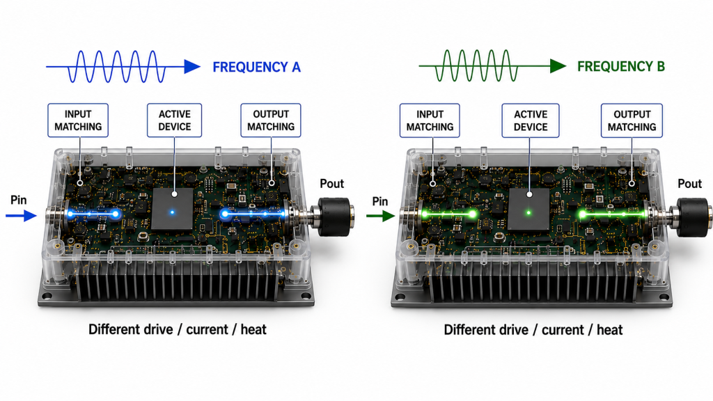
This does not mean a wideband PA is unstable or unsuitable. It means the frequency label alone cannot show how the module behaves at every frequency a real project may use.
For example, two points inside the same rated band may both meet the required Pout, but one may need more RF drive or draw more DC current under comparable conditions. That difference matters because the more demanding operating point may reduce power-supply or thermal margin even though the frequency itself remains inside the published range.
Load condition can also influence the result. A measurement into a controlled dummy load and operation through a real RF path do not represent the same boundary. Reflected power, cables, filters, switches, connectors, and antenna conditions can change what the PA sees at its output.
The engineering question is therefore not:
Does this PA cover the required band?
It is:
Under comparable test conditions, what output, drive requirement, current, efficiency, temperature, and protection behavior does it show at the frequencies the project will actually use?
2.Why Is One Typical Efficiency Number Not Enough?
A datasheet value such as “35% typical efficiency” can be useful for initial screening, but it is not enough for frequency-by-frequency approval.
Before comparing percentages, engineers need to know what the percentage means. PAE, drain efficiency, module DC-to-RF efficiency, and wider system efficiency use different electrical boundaries.
The distinction between these metrics is covered separately in PAE vs Drain Efficiency in RF PA Evaluation. For a frequency comparison, the important rule is straightforward:
Use the same efficiency definition and the same RF and DC measurement boundaries at every point being compared.
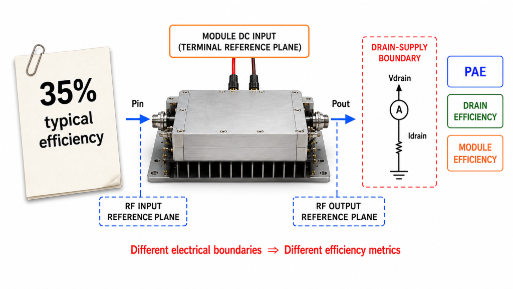
A useful test report should state:
- Actual frequency
- Efficiency metric and formula
- Actual Pin at the defined PA input reference plane
- Pout at the defined PA output reference plane
- DC voltage and current at the boundary used by the selected efficiency metric
- Load or VSWR condition
- Signal type
- Duty cycle and test duration
- Cold-state or stabilized hot-state condition
- Cooling condition
- Protection status
The Pin-control method also matters.
One test may keep actual measured Pin constant to see how gain, Pout, current, and temperature vary with frequency. Another may adjust Pin at each frequency until the PA reaches a defined target Pout.
Both methods can answer useful questions, but they answer different questions. The report should state which method was used.
Do not compare a cold center-frequency result at one output level with a hot band-edge result at another output level and call the difference a frequency effect.
3.Which Frequency Points Should You Compare?
Start with the frequencies the project will actually use.
If a system requires only several defined operating points, those points matter more than a generic low / center / high demonstration. If the project uses a broader continuous range, additional sweep points may be needed to identify the weakest verified operating region.
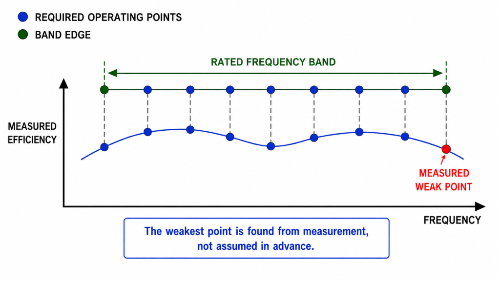
Band-edge points deserve separate verification when they are part of the real operating range. However, they should not automatically be assumed to be the least efficient points before measurement.
The purpose of testing is to find the weak point, not to pre-select it.
A center-frequency result cannot automatically prove the low edge, high edge, or another critical channel. In the same way, a good band-edge result does not prove that every intermediate point behaves identically.
Where band-edge acceptance itself is the main question, the RF PA band-edge performance test should define Pin control, Pout limits, output reference plane, duty cycle, load condition, hot-state behavior, and protection response.
For remote or difficult-to-maintain C-UAS installations, discovering a weak frequency point after deployment can be more costly than identifying it during pre-RFQ testing. That increases the value of target-frequency evidence, but the comparison itself should still be based on measurable RF, DC, load, and thermal conditions rather than the deployment label.
4.What Do Efficiency Changes Mean for Current and Heat?
Frequency-dependent efficiency becomes a system issue when the electrical power required at one operating point differs from another.
At a defined DC measurement boundary, electrical input power is calculated from the voltage and current measured at that same boundary:
Pdc = Vdc × Idc
If Vdc and Idc are measured at the PA module terminals, this represents module DC input power. It should not be treated as transistor or final-stage drain power unless the efficiency metric is explicitly defined at that drain-supply boundary.
That distinction matters when interpreting different efficiency metrics.
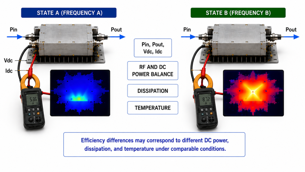
For drain efficiency or a defined module DC-to-RF efficiency, lower efficiency at the same Pout and the same DC measurement boundary means more DC input power is required. If that DC voltage remains constant, the higher DC power appears as higher current.
PAE requires a different interpretation because Pin is part of the calculation.
At the same Pout, lower PAE may result from:
- Higher RF input drive
- Higher DC input power
- Both higher RF drive and higher DC input power
Pin, Pout, Vdc, and Idc should therefore be reviewed together before a frequency point is judged.
Higher Idc by itself also does not prove lower efficiency. The comparison is meaningful only when Pout, Vdc, the efficiency metric, RF drive rule, load condition, and measurement boundary are comparable. Otherwise, the current difference may come from a different output target, drive condition, supply condition, load, or operating state.
Heat requires the same boundary discipline.
Do not infer module heat from an efficiency percentage alone until the efficiency metric and its RF and DC power boundaries are defined. Thermal load should be derived from the actual power balance at that boundary rather than by applying one generic “1 − efficiency” calculation to PAE, drain efficiency, and module efficiency interchangeably.
When thermal dissipation must be quantified, RF PA heat load should be calculated from the defined electrical power balance rather than from an undefined efficiency percentage.
The correct engineering chain is:
Operating point → RF and DC power balance → dissipation → temperature response → electrical or protection behavior
Not:
Lower efficiency → failure
A frequency point with higher dissipation may still operate correctly if the power-supply, thermal, and protection margins are sufficient.
The same caution applies to alarms.
A temperature, VSWR, or protection event that occurs while one frequency is active shows correlation, not root cause. Engineers should review load condition, forward and reflected power, module-terminal voltage and current, cooling, temperature, and protection records before blaming the frequency point or the PA itself.
5.What Evidence Should Be Recorded at Each Frequency?
The most useful frequency-efficiency report is not the one with the largest number of screenshots. It is the one that lets engineers compare operating points under a traceable and consistent measurement boundary.
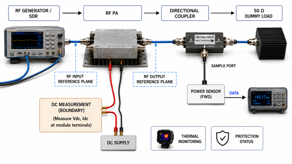
| Evidence item | What to keep constant or record | Why it matters |
|---|---|---|
| Target frequency | Record every required operating point | Identifies exactly which point the result represents |
| Efficiency metric | Use the same metric and formula | Prevents PAE, drain, and module-efficiency confusion |
| Pin and Pout | Record actual values at defined RF reference planes | Defines the RF operating condition |
| RF-path corrections | Apply and record frequency-specific cable, attenuator, coupler, connector, adapter, and fixture corrections | Prevents test-path frequency response from being mistaken for PA efficiency variation |
| DC voltage and current | Record voltage and current at the DC boundary used by the selected efficiency metric; identify whether this is the module input or drain-supply boundary | Prevents module DC power from being confused with drain-stage DC power |
| Load condition | Define dummy load, VSWR, or other agreed load boundary | Separates frequency effects from load effects |
| Thermal condition | State ambient, cooling, cold/hot state, duty cycle, and duration | Makes thermal results comparable |
| Protection and traceability | Record alarms, recovery behavior, test unit, and report linkage | Helps distinguish normal operation, protection action, and unit-level evidence |
Any Pin or Pout value used for a frequency-efficiency comparison should be referred to the defined PA input or output plane using the correction factor applicable at that frequency.
Cable, attenuator, coupler, connector, adapter, and fixture losses can change across the test band. Without frequency-specific correction, part of the apparent efficiency trend may come from the measurement path rather than from the PA itself.
The output reference plane deserves particular attention. A low-frequency Pout measured directly at the PA connector cannot be fairly compared with a high-frequency result measured after a feeder, filter, or switch unless the measurement boundaries and applicable corrections are explicitly reconciled.
The same applies to RF input power. If Pin is measured before a frequency-dependent input cable or fixture, the loss between the instrument and the defined PA input plane should be accounted for before the value is used in PAE or gain calculations.
When RF power values are used in an efficiency calculation, they should first be converted to linear power units such as watts. Raw dBm values should not be inserted directly into equations that combine RF power with DC power in watts.
Hot-state evidence also needs a defined boundary.
A short measurement after the case becomes warm is not automatically equivalent to a stabilized long-duty operating condition. The report should state the duty cycle, duration, cooling configuration, ambient condition, and the criterion used to identify the reported thermal state.
When protection activity appears, the record should show what happened before, during, and after the event. Useful context can include Pout, Vdc, Idc, temperature, forward and reflected power, alarm status, and recovery behavior.
For acceptance work, S/N-linked evidence can further reduce the gap between a generic model-level claim and the actual delivered unit under review.
6.What Should the RFQ Require Before Module Approval?
RFQ language should convert “good efficiency across the band” into conditions that a supplier can actually measure and an integrator can later review.
A weak request is:
Need a high-efficiency wideband RF PA.
A stronger request defines which frequencies must work, what output is required, how efficiency will be measured, which RF and DC boundaries apply, and under what electrical, RF, and thermal conditions the evidence must be produced.
| RFQ item | Customer input needed | What it confirms |
|---|---|---|
| Target frequencies | Actual required operating points or range | Defines where evidence is needed |
| Required Pout | Minimum or target output at each critical point | Creates the RF performance boundary |
| Pin-control rule | Constant measured Pin or adjusted drive to target Pout | Makes frequency comparisons interpretable |
| Efficiency metric and boundary | PAE, drain efficiency, module efficiency, or project-defined metric, including the RF and DC measurement boundaries | Prevents percentage and measurement-boundary mismatch |
| Measurement plane | PA input/output, cabinet output, or another defined reference plane | Prevents RF-path ambiguity |
| DC requirement | Module-terminal or project-defined supply voltage and applicable current limit | Defines electrical margin |
| Operating condition | Signal type, duty cycle, duration, cooling, and ambient condition | Defines hot-state relevance |
| Load / protection boundary | Load or VSWR condition plus required alarm, foldback, shutdown, and recovery behavior | Defines acceptable protection operation |
| Report requirement | Required data, frequency-specific corrections, pass/fail status, and S/N linkage if applicable | Makes the result reviewable before acceptance |
This is also where efficiency testing moves naturally into module selection.
The widest frequency label should not automatically win. A wideband architecture may simplify the RF chain, while a band-specific route may offer better margin at a smaller set of required frequencies. The decision should follow measured operating-point evidence rather than an assumption about which architecture must be better.
For projects that genuinely require broad multi-band coverage, RF SKYPOWER’s Wideband RF Power Amplifier Modules provide a practical starting point for engineering review. Final approval should still be based on the project-defined frequencies, output requirements, RF and DC measurement boundaries, cooling condition, load condition, and required test evidence.
FAQ
Should RF PA efficiency always be compared at the same RF output level?
Use the same target Pout when the engineering question is how much DC power or current each frequency requires to produce the required output. A constant-Pin test is also valid when the goal is to compare gain, Pout, current, and thermal behavior under the same measured RF input drive.
In either case, the test mode, efficiency definition, RF reference planes, and DC measurement boundary should remain consistent across the frequencies being compared.
Are band-edge frequencies always less efficient?
No. Band-edge points may be more demanding in some designs, but the weakest efficiency point should be identified from measurement rather than assumed in advance.
Test the edges when they are part of the required range, along with other critical project frequencies.
What if a supplier provides only one typical efficiency value?
Treat it as preliminary information, not full-band acceptance evidence.
Ask which efficiency metric was used, which RF and DC measurement boundaries apply, the associated Pin and Pout, Vdc and Idc, load condition, thermal state, and whether comparable data is available at the frequencies your project actually requires.
Conclusion
RF PA efficiency can change across frequency bands because device behavior, matching, gain, RF drive requirement, load interaction, and electrical and thermal operating conditions can vary with frequency. A wide frequency rating therefore proves operating coverage, but it does not prove equal efficiency, current demand, heat dissipation, or operating margin at every point.
The correct comparison uses the same efficiency definition and measurement boundaries, applies frequency-specific RF-path corrections, defines the Pin-control method, and compares the actual project frequencies under consistent output, load, DC, and thermal conditions. Band edges should be tested when they matter, but the weakest point should be found from evidence rather than assumed.
Before requesting a quote, send RF SKYPOWER your target frequencies, required Pout at each point, RF input-drive condition, efficiency metric and measurement boundaries, DC voltage and current limits, duty cycle, cooling boundary, load or VSWR condition, protection requirements, and the test evidence required for acceptance. Our RF engineering team can then review whether a wideband or band-specific RF PA route fits the project under the actual operating conditions.