











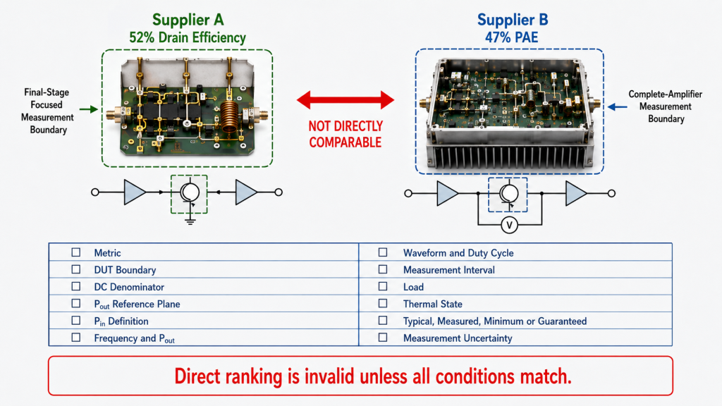
PAE vs Drain Efficiency can make one RF power amplifier appear better than another even when the two percentages do not measure the same thing. Supplier A may quote 52% drain efficiency, while Supplier B quotes 47% PAE. The first number is higher, but its DC boundary, RF input power, output reference plane, and test condition may be completely different.
Choosing the larger percentage without checking those definitions can lead to the wrong PA architecture comparison, an inaccurate 28 V current estimate, or an undersized cooling system.
Does 52% drain efficiency prove that Supplier A has the more efficient RF PA—or are the two suppliers measuring different things?
1. What Is the Difference Between PAE and Drain Efficiency?
PAE and drain efficiency both describe RF power conversion, but they answer different engineering questions.
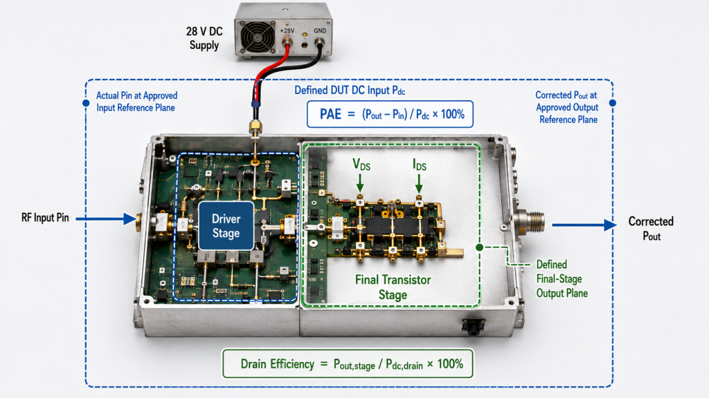
Drain Efficiency
Drain efficiency compares RF output power with the DC power delivered to the transistor drain or defined final-stage drain supplies:
Drain Efficiency (%) = Pout / Pdc,drain × 100%
For one drain rail:
Pdc,drain = VDS × IDS
For multiple drain rails:
Total Pdc,drain = Σ(VDS,i × IDS,i)
Drain efficiency is most useful for evaluating:
- Transistor performance
- Final-stage conversion
- Matching-network behavior
- Bias and operating-class choices
- Device or final-stage architecture
It does not automatically include:
- RF input power
- Driver-stage DC power
- Control electronics
- DC-DC converter loss
- Cooling fans
- External system loads
The Pout reference plane must be stated together with the drain boundary. A transistor-plane result, a final-stage output result, and a module-connector result may all use drain DC power, but they do not represent exactly the same conversion boundary.
A value described as drain efficiency should therefore identify:
- The included drain rails
- The defined final-stage boundary
- The Pout reference plane
- The RF power definition
- The operating condition
Power-Added Efficiency
Power-added efficiency compares the net RF power added by the DUT with the DC power entering the defined PA boundary:
PAE (%) = (Pout − Pin) / Pdc × 100%
where:
Poutis corrected RF output power at the approved output reference planePinis actual RF input power at the approved input reference planePdcis the DC power entering the stated DUT boundary
Pout and Pin must use the same linear unit, normally watts.
PAE is useful when amplifiers require different Pin to produce the same Pout. It shows how much net RF power the DUT adds relative to its defined DC input.
However, PAE does not automatically include the DC power consumed by an external driver, SDR, or exciter that produces Pin. It subtracts RF Pin—not the upstream equipment’s total DC consumption.
The Pin definition should also state whether it represents incident or delivered RF power at the approved DUT input plane, especially when input mismatch is not negligible.
The complete RF PA PAE measurement boundary should identify whether the result applies to an RF stage, PA module, or larger assembly.
Module and System DC-to-RF Efficiency
Neither drain efficiency nor PAE automatically proves the full DC burden of an installed system.
| Metric | Basic Boundary | Best Used For | Does Not Prove Alone |
|---|---|---|---|
| Drain efficiency | RF output divided by final-stage drain DC power | Transistor or final-stage conversion | Total module current or external driver burden |
| PAE | Net RF power added divided by defined DUT DC input | Amplifier comparison when Pin differs | Complete upstream or cabinet DC consumption |
| Module DC-to-RF efficiency | Module RF output divided by total module DC input | Module-level current and heat comparison | Internal final-stage conversion |
| System DC-to-RF efficiency | Defined system RF output divided by total system DC input | Cabinet or platform power budgeting | Individual PA-stage behavior |
| Actual Vdc and Idc | Measured module-terminal voltage and current | Supply, cable, fuse, and connector sizing | RF conversion quality by themselves |
The metric name and electrical boundary must be stated together.
A percentage that includes drivers, controllers, converters, or cooling hardware should not be compared directly with transistor drain efficiency.
2. Why Can PAE and Drain Efficiency Show Different Results?
PAE and drain efficiency differ because PAE subtracts Pin.
When both metrics use the same:
- DUT boundary
- DC denominator
- Pout reference plane
- RF power definition
- Operating point
then:
Drain Efficiency = Pout / Pdc
PAE = (Pout − Pin) / Pdc
Therefore:
PAE = Drain Efficiency − Pin / Pdc
If linear power gain is:
Gp = Pout / Pin
then:
PAE = Drain Efficiency × (1 − 1 / Gp)
These relationships cannot be used when drain efficiency and PAE use different DC denominators, different Pout planes, or different RF power definitions.
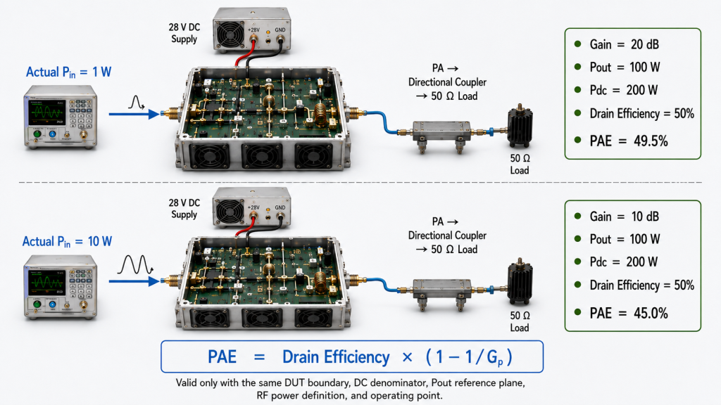
High Gain Makes the Values Closer
Assume:
- Pout =
100 W - Pin =
1 W - Pdc =
200 W
Drain efficiency is:
100 / 200 = 50%
PAE is:
(100 − 1) / 200 = 49.5%
The difference is only 0.5 percentage point.
Lower Gain Increases the Difference
Now keep Pout and Pdc unchanged but increase Pin:
- Pout =
100 W - Pin =
10 W - Pdc =
200 W
Drain efficiency remains:
100 / 200 = 50%
PAE becomes:
(100 − 10) / 200 = 45%
| Actual Pin | Linear Power Gain | Gain | Drain Efficiency | PAE |
|---|---|---|---|---|
| 1 W | 100 | 20 dB | 50% | 49.5% |
| 10 W | 10 | 10 dB | 50% | 45.0% |
Both operating points show the same drain efficiency because Pout and drain DC power are unchanged.
Their PAE values differ because one amplifier adds less net RF power for the same DC input.
The Higher Percentage Does Not Prove the Better System
The example still does not prove which complete RF chain consumes less DC power.
The external driver producing 10 W Pin may consume substantially more than 10 W from its own DC supply. That driver loss is not automatically included in the PA’s drain efficiency or PAE.
A complete system comparison may require:
- PA-module DC power
- External driver DC power
- SDR or exciter power
- Converter loss
- Distribution loss
- Cooling power
- Simultaneous-channel operating condition
PAE is more sensitive to required Pin than drain efficiency, but it is not the same as system DC-to-RF efficiency.
3. When Should Engineers Use PAE or Drain Efficiency?
Neither metric is universally better.
The correct metric depends on the engineering decision.
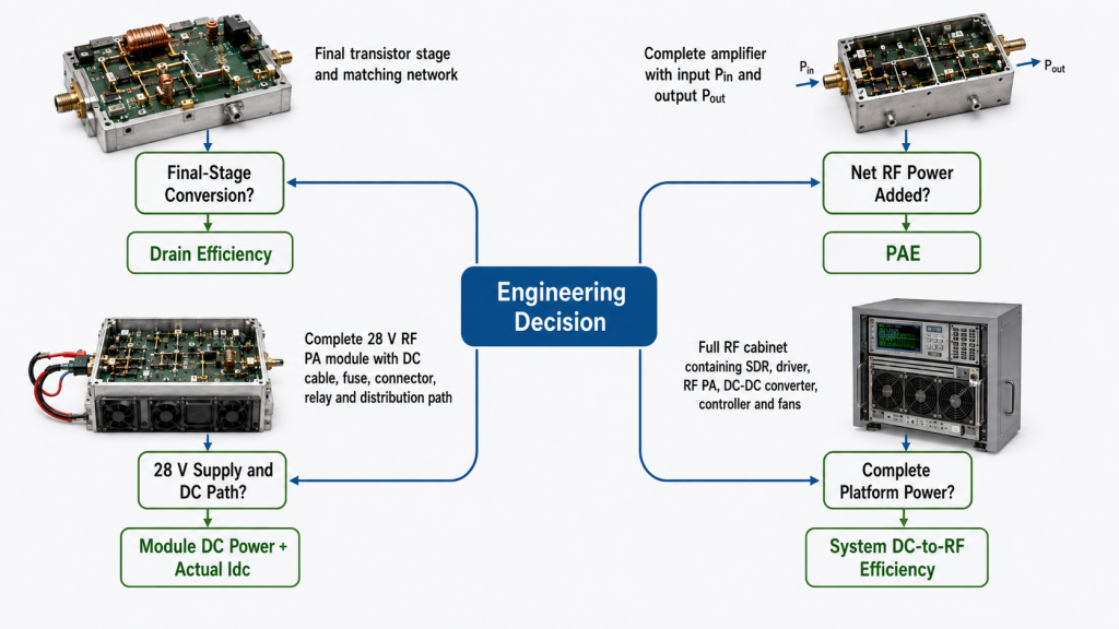
Use Drain Efficiency for Final-Stage Evaluation
Drain efficiency is normally the better metric when the question is:
- How effectively does the final transistor stage convert drain DC power into RF output?
- How do matching, bias, load impedance, or operating class affect the final stage?
- Which transistor or final-stage architecture has better DC-to-RF conversion?
- How does the final stage behave across frequency or output level?
The compared results should use the same:
- Drain boundary
- Pout reference plane
- Bias condition
- Frequency
- Pout
- Load
- Waveform
- Thermal state
Drain efficiency should not be used alone to size the complete PA-module supply or cooling system.
Use PAE for Net Added RF Power
PAE is more informative when the question is:
- How much net RF power does the DUT add relative to its DC input?
- Does one amplifier require substantially more Pin than another?
- Does gain variation change the efficiency comparison?
- Is a high drain-efficiency result dependent on unusually high input drive?
The test must use actual RF PA input power, not only the signal-generator setting.
Use Module DC Evidence for 28 V Integration
When the decision concerns:
- 28 V power-supply capacity
- DC cable size
- Fuse rating
- Connector current
- Relay capacity
- Module thermal load
- Cabinet power budgeting
the customer needs total module DC input and actual Idc.
The relevant relationship is:
Pdc,module = Vmodule × Imodule
and, where useful:
Module DC-to-RF Efficiency = Pout / Pdc,module × 100%
Drain efficiency may exclude driver, bias, control, and conversion losses.
PAE may also exclude loads outside its defined DUT boundary.
Use System DC-to-RF Efficiency for Complete Platforms
For a complete cabinet, vehicle, or multi-channel platform:
System DC-to-RF Efficiency = Defined System RF Output / Total System DC Input × 100%
The denominator may include:
- RF PA modules
- Drivers
- SDRs or exciters
- DC-DC converters
- RF switches
- Control electronics
- Fans
- Distribution losses
This result should be labelled system DC-to-RF efficiency—not drain efficiency or RF-stage PAE.
4. What Must Match Before the Numbers Are Compared?
A larger percentage proves very little unless the underlying conditions match.
| Comparison Condition | What Must Be Defined |
|---|---|
| Metric | Drain efficiency, PAE, module DC-to-RF efficiency, or system DC-to-RF efficiency |
| DUT boundary | Transistor, final stage, PA module, assembly, or complete system |
| DC denominator | Included drain rails, module rails, auxiliary loads, and converters |
| Pout reference plane | Transistor plane, final-stage output, module connector, or installed path |
| Pin definition | Incident or delivered power at the approved input plane |
| Frequency and Pout | Same frequency point and output condition |
| Waveform | CW, pulsed, burst, or modulated |
| Duty cycle and averaging | Same RF and DC measurement interval |
| Load | Same 50 Ω or approved mismatch condition |
| Thermal state | Cold, warmed, or thermally stabilized |
| Value type | Typical, measured, minimum, or guaranteed |
| Uncertainty | Compatible measurement and pass/fail rules |
If these conditions differ, the percentages should not be ranked directly.
A centre-frequency rated-power drain-efficiency result should not be compared with a hot-state band-edge PAE result.
When the application uses multiple output levels, RF PA efficiency at power back-off should be reviewed separately.
5. What Do These Metrics Mean for 28 V Power and Heat?
Efficiency percentages become useful to system integrators only when they connect to actual DC input and a clearly defined thermal boundary.
Final-Stage Dissipation
For a defined final-stage boundary that receives RF Pin and drain DC power:
Final-Stage Dissipation ≈ Pdc,drain + Pin,stage − Pout,stage
If Pin,stage is small compared with Pout, engineers may use the simplified estimate:
Final-Stage Dissipation ≈ Pdc,drain − Pout,stage
The approximation should not silently omit material auxiliary DC rails or other RF output components.
PA-Module Dissipation
For a defined PA-module boundary:
PA-Module Dissipation ≈ Pdc,module + Pin,module − Pout,module
This is a practical steady-state estimate.
If Pout includes only the fundamental output, harmonic, spurious, or other emitted RF power may not be explicitly included. The RF output definition should therefore be stated when high-accuracy thermal accounting is required.
Actual 28 V Current
For a PA module operating at 28.0 V:
Imodule = Pdc,module / Vmodule
For example, if measured module DC input is 220 W:
Imodule = 220 W / 28.0 V = 7.86 A
This current—not a drain-efficiency percentage alone—should guide:
- Power-supply sizing
- DC cable selection
- Fuse rating
- Connector selection
- Relay capacity
- Distribution-board margin
Heat Must Follow the Same Boundary
Assume:
- Pout =
100 W - Pin =
1 W - Total PA-module DC input =
220 W
Approximate PA-module dissipation is:
220 + 1 − 100 = 121 W
If another supplier quotes only 50% drain efficiency, that value cannot define complete module heat unless the excluded driver, bias, control, and conversion loads are also known.
The full relationship between RF PA efficiency and cabinet heat also depends on:
- Thermal interface
- Heatsink
- Airflow
- Fan performance
- Ambient temperature
- Enclosure restriction
- Simultaneous-channel operation
- Hot-state output stability
Neither PAE nor drain efficiency replaces direct module-current and thermal validation.
RFQ: Which Efficiency Evidence Should Suppliers Provide?
Do not request only:
Efficiency: 50%
Request the evidence needed to identify and compare the metric:
- Metric name: drain efficiency, PAE, module DC-to-RF efficiency, or system DC-to-RF efficiency
- Equation used
- DUT and electrical boundary
- Included DC rails and auxiliary loads
- Pout reference plane
- Actual Pin and its incident/delivered definition
- Pout, Vdc, Idc, and calculated Pdc
- Frequency and output condition
- Waveform and duty cycle
- Load and thermal state
- Typical, measured, minimum, or guaranteed status
- Measurement uncertainty
- Model and serial number
- S/N-linked test evidence, where required
The required metric should be confirmed for the selected Custom RF Power Amplifier Modules configuration rather than inferred from one isolated percentage.
Conclusion
Neither PAE nor drain efficiency is universally the better RF PA metric. The trustworthy number is the one whose metric, electrical boundary, output reference plane, operating point, and measurement evidence match the decision you need to make.
Use drain efficiency to compare DC-to-RF conversion at the same transistor or final-stage drain boundary. Use PAE to compare the net RF power added by amplifiers when actual Pin differs. Use module DC power, actual Idc, or module DC-to-RF efficiency when sizing a 28 V supply, DC path, or module cooling system. Use system DC-to-RF efficiency when the decision includes drivers, controllers, converters, fans, and other platform loads.
PAE and drain efficiency can be compared only when the DUT boundary, DC denominator, Pout reference plane, RF power definition, frequency, Pout, Pin, waveform, load, thermal state, and measurement interval are matched.
The decision rule is direct:
- Accept a drain-efficiency comparison only when both results use the same drain boundary, Pout plane, and operating point.
- Use PAE for amplifier comparison only when actual Pin and the same DUT DC boundary are defined.
- Request module-level DC evidence when the decision concerns 28 V current, module heat, or power-supply capacity.
- Reject a direct percentage comparison when one supplier quotes drain efficiency and another quotes PAE without supporting Pout, Pin, Vdc, Idc, and boundary definitions.
A larger percentage does not prove a better RF PA when the suppliers are measuring different things.
RF SKYPOWER can review the required efficiency metric and test boundary before the RF PA configuration is finalized.
Submit the required frequency points, Pout, available Pin, 28 V current limit, waveform, duty cycle, load, cooling condition, hot-state requirement, and whether the project needs drain efficiency, PAE, module DC-to-RF efficiency, system DC-to-RF efficiency, or S/N-linked acceptance evidence.