











RF PA PAE may appear as one clear percentage on a datasheet, quotation, or test report. Two suppliers may both quote 45%, yet one value may come from corrected PA-port measurements while the other uses a signal-generator setting, nominal current, or RF and DC readings captured at different times.
The percentages may look directly comparable, but the electrical boundary, waveform, output level, temperature, and measurement method behind them can be completely different. A wrong comparison can lead to an undersized 28 V supply, insufficient cooling, unrealistic cabinet estimates, or rejection of a PA tested under a different operating condition.
If two RF PA suppliers quote the same PAE, how do you know whether the percentages were calculated from the same power boundary—and whether either value represents your real operating point?
1. What Does PAE in an RF Power Amplifier Actually Measure?
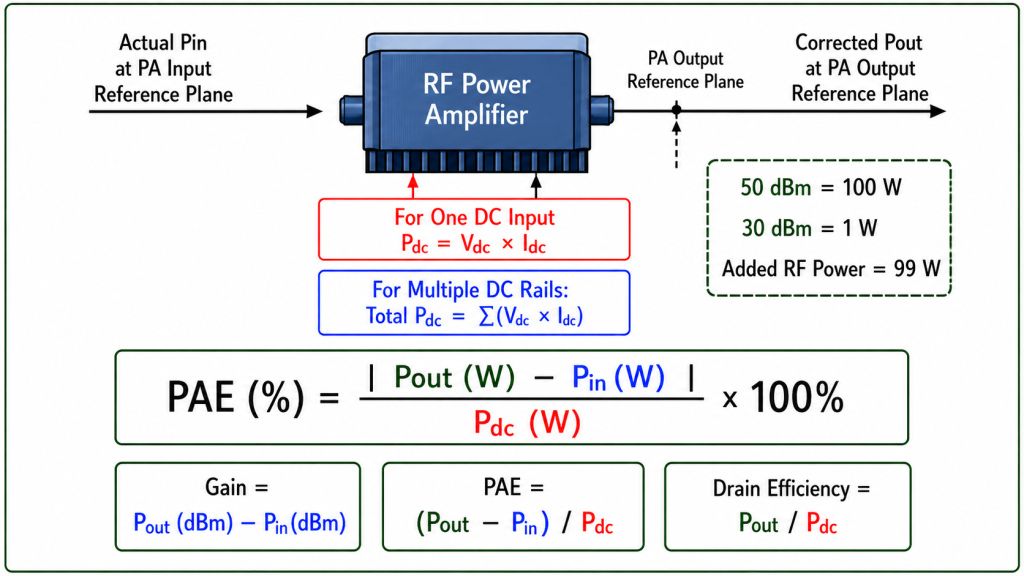
Power-added efficiency measures how effectively an RF power amplifier converts DC input power into additional RF output power.
The standard equation is:
PAE (%) = [Pout(W) − Pin(W)] / Pdc(W) × 100%
where:
Poutis the corrected RF output power at the approved PA output reference planePinis the actual RF input power at the approved PA input reference planePdcis the total DC power entering the defined electrical boundary
For one DC input:
Pdc(W) = Vdc(V) × Idc(A)
For multiple DC rails:
Total Pdc(W) = Σ[Vi(V) × Ii(A)]
Every included rail must be identified. Depending on the approved boundary, this may include:
- Main PA supply
- Driver supply
- Bias supply
- DC-DC converter input
- Control or monitoring supply
External cabinet fans, controllers, and unrelated electronics should not be silently included in a number labelled RF-stage PAE.
Pout and Pin Must Use Linear Power
Pout and Pin must use the same linear unit, normally watts or milliwatts.
Do not subtract dBm values directly.
If the RF readings are recorded in dBm, convert them first:
P(W) = 10^[(P(dBm) − 30) / 10]
For example:
50 dBm = 100 W30 dBm = 1 W
The added RF power is:
100 W − 1 W = 99 W
It is not:
50 dBm − 30 dBm = 20 W
Subtracting two dBm values produces a gain of 20 dB, not an RF power difference of 20 W.
Use PAE as a Decimal in Rearranged Equations
When PAE is used in calculations such as:
Pdc = (Pout − Pin) / PAE
the percentage must be entered as a decimal.
For example:
40% = 0.4050% = 0.50
Do not enter 40 when the equation requires 0.40.
PAE and Gain Answer Different Questions
Gain compares RF output power with RF input power:
Gain(dB) = Corrected Pout(dBm) − Actual Pin(dBm)
PAE compares added linear RF power with DC input power.
A PA can therefore show:
- High gain but moderate PAE
- Similar gain with different current
- Similar Pout with different PAE
- Similar PAE at one frequency but different PAE elsewhere
Gain cannot replace PAE, and PAE cannot replace gain.
PAE and Drain Efficiency Are Not the Same
Drain efficiency normally uses:
Drain Efficiency = Pout / Pdc × 100%
PAE subtracts Pin first:
PAE = (Pout − Pin) / Pdc × 100%
The difference may be small when Pin is negligible compared with Pout. It becomes more important when substantial RF drive is required.
A detailed comparison of PAE and drain efficiency boundaries should use the same RF output, DC boundary, waveform, frequency, and operating point.
2. Why Can a Correct PAE Formula Still Produce the Wrong Result?
A report may show the correct equation while using invalid inputs.
The most common problem is not the formula. It is the shortcut used to obtain Pout, Pin, Vdc, Idc, or the measurement time state.
| PAE Input | Correct Value | Wrong Shortcut | Why the Shortcut Fails |
|---|---|---|---|
| Pout | Corrected PA-port output in W | Raw sensor reading or a dBm number | Omits path corrections or uses the wrong unit |
| Pin | Actual PA-port input in W | Signal-generator setting | Ignores source-path loss, gain, and frequency response |
| Vdc | PA-terminal voltage under load | Power-supply setpoint | Ignores DC cable and connector voltage drop |
| Idc | Current measured for the same operating interval | Catalogue, nominal, or current-limit value | Does not represent actual DC consumption |
| Time state | RF and DC values from the same interval | Mixed cold, hot, peak, or averaged data | Creates an operating point that never existed |
| Waveform | Defined CW, pulsed, or modulated condition | Unstated signal type | Peak and average values may be mixed |
| Electrical boundary | Named RF-stage, module, or assembly boundary | Different loads included by different suppliers | Produces percentages that are not directly comparable |
Generator Setting Is Not Actual Pin
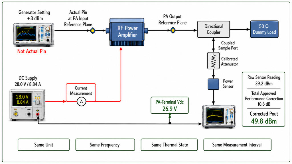
The signal generator may display +3 dBm, but the PA may receive a different input because of:
- Driver gain or loss
- Test cable loss
- Connector loss
- Switch insertion loss
- Attenuator tolerance
- Frequency response
- Temperature drift
- Source-leveling error
PAE must use actual Pin at the approved PA input reference plane.
The complete method for establishing actual RF PA input power should define the source path, correction values, frequency, and reference plane.
Raw Sensor Power Is Not Corrected Pout
Corrected Pout should be calculated as:
Corrected Pout = Raw Sensor Reading + Total Approved Path Correction
The total correction may include:
- Directional-coupler coupling factor
- Attenuator value
- Test cable loss
- Connector loss
- Adapter loss
- Frequency-specific calibration
For example, assume:
- Raw sensor reading:
39.2 dBm - Total approved path correction:
10.6 dB
Then:
Corrected Pout = 39.2 + 10.6 = 49.8 dBm
The report should identify how the 10.6 dB total was built. A correction labelled only “cable loss” is insufficient if the path also contains a coupler or attenuator.
Supply Setpoint Is Not PA-Terminal Vdc
A supply may be set to 28.0 V, while the operating PA receives less because of:
- DC cable resistance
- Connector resistance
- Fuse or relay loss
- Distribution-board loss
- Supply droop
- High current demand
If the module terminals receive 26.9 V, the PAE calculation should not silently use the 28.0 V setpoint.
Nominal Current Is Not Measured Idc
PAE must not use:
- Catalogue current
- Current limit
- Rounded estimate
- Data from another sample
- Cold-state current combined with hot-state RF power
Idc must apply to the same unit and operating interval as Pout and Pin.
3. How Should Pout, Pin, Vdc, and Idc Be Measured?
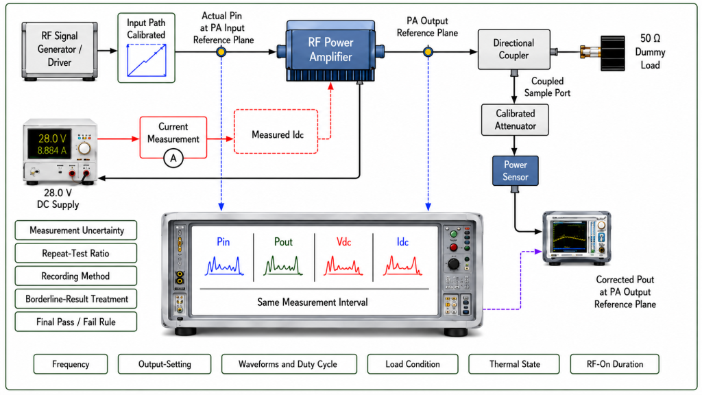
A defensible PAE result requires:
- Defined RF reference planes
- A named DC boundary
- Time-aligned RF and DC measurements
- A defined waveform and averaging method
- A controlled thermal state
- Known measurement uncertainty
Define the RF Reference Planes
The report should identify:
- PA input connector or approved input plane
- PA output connector or approved output plane
- Input-path corrections
- Output-path corrections
- Coupler and attenuator corrections
- Frequency-specific correction values
The final record should show actual Pin and corrected Pout at those approved planes.
Name the Electrical Boundary
Different boundaries should use different names.
RF-stage PAE
Includes only the defined RF amplification stage and its applicable DC rails.
PA-module PAE
May include internal driver, control, bias, or conversion circuits inside the module boundary.
Assembly-level efficiency
May include additional switches, control boards, converters, or integrated cooling hardware.
System DC-to-RF efficiency
May include cabinet-level loads such as fans, controllers, distribution losses, or other electronics.
These numbers may all be useful, but they are not interchangeable.
If fans, external controllers, or cabinet electronics are included, the result should not be compared directly with RF-stage PAE without identifying the changed boundary.
Align RF and DC Measurements
Pout, Pin, Vdc, and Idc must represent the same:
- Frequency
- Output setting
- Waveform
- Duty cycle
- Load condition
- Thermal state
- Measurement interval
A cold-start Pout value cannot be combined with hot-state current measured later.
A peak RF value should not be combined with a slowly averaged current display unless the approved calculation explicitly defines that method.
Average PAE and Instantaneous PAE Are Different
For steady CW operation, stabilized RF and DC readings are normally sufficient.
For pulsed or modulated operation, the report must state whether it provides:
- Average PAE
- Pulse PAE
- Instantaneous or envelope PAE
For average PAE:
Average PAE = [Average Pout − Average Pin] / Average Pdc × 100%
Average Pout, average Pin, and average Pdc must cover the same measurement interval.
Unless instantaneous or envelope PAE is explicitly required, pulsed or modulated tests should normally use time-aligned average RF and DC values.
Do not combine:
- Peak Pout
- Average Pin
- Low-bandwidth average current
in one PAE result.
Define the Current Measurement Method
For CW operation, a stable current reading may be adequate.
For pulsed, burst, or rapidly switched operation, record:
- Current-sensor bandwidth
- Supply telemetry update rate
- Sampling interval
- Trigger method
- Integration window
- Averaging method
- Data synchronization
A slowly updated power-supply display may not capture the current behavior needed for a dynamic PAE calculation.
Record the Thermal State
PAE may change after warm-up because the following can change:
- Gain
- Required Pin
- Pout
- Bias condition
- Current
- PA-terminal voltage
- Protection behavior
The report should identify whether the value represents:
- Initial cold state
- Defined warm-up point
- Thermally stabilized state
- End of a continuous-power run
- High-ambient condition
Include Measurement Uncertainty
The acceptance record should define:
- RF instrument accuracy
- RF path-correction uncertainty
- Voltage-measurement uncertainty
- Current-measurement uncertainty
- Timing or synchronization uncertainty
- Repeat-test requirement
- Rounding method
- Borderline-result treatment
- Final pass/fail rule
A measured value of 44.9% should not automatically fail or pass a 45% requirement without the approved uncertainty and decision rule.
4. What Does PAE Mean for 28 V Current and Heat?
PAE becomes useful to system integrators when it is translated into DC current and module dissipation.
From the PAE equation:
Pdc = (Pout − Pin) / PAE
For a 28 V system:
Idc = Pdc / 28 V
A practical steady-state estimate of module dissipation is:
Module Dissipation ≈ Pdc + Pin − Pout
The same relationship can be written as:
Module Dissipation ≈ Pdc × (1 − PAE)
This is a practical engineering estimate under a defined steady-state boundary.
For precision calorimetric analysis, the RF output definition should state whether Pout represents only the fundamental output or includes other emitted RF power. If harmonic and spurious output are negligible, the simplified estimate is normally suitable for system-level thermal planning.
Illustrative 100 W Example
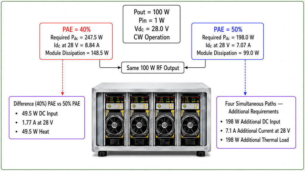
Assume:
- Pout =
100 W - Pin =
1 W - Vdc =
28.0 V - CW operation
- Same RF and DC measurement interval
- Defined PA-module boundary
| PAE | Required Pdc | Approximate Idc at 28 V | Module Dissipation |
|---|---|---|---|
| 40% | 247.5 W | 8.84 A | 148.5 W |
| 50% | 198.0 W | 7.07 A | 99.0 W |
These are illustrative calculations, not guaranteed product values.
Both operating points deliver the same 100 W RF output. However, the 40% PAE case requires approximately:
49.5 Wmore DC input1.77 Amore current at 28 V49.5 Wmore heat removal
This difference affects:
- Power-supply capacity
- DC cable sizing
- Connector rating
- Fuse and relay margin
- Heatsink size
- Airflow
- Cabinet temperature
- Multi-channel power budgeting
Multi-Channel Consequences
If four identical paths operate simultaneously, the illustrative difference becomes approximately:
198 Wadditional DC input7.1 Aadditional current at 28 V198 Wadditional thermal load
This is why RF output power alone cannot define the cabinet power and cooling requirement.
The complete relationship between RF PA efficiency and cabinet heat also depends on ambient temperature, airflow, thermal interfaces, fan performance, enclosure restriction, and installation conditions.
PAE provides one part of the evidence. It does not replace thermal validation.
5. Why Can One PAE Value Fail to Represent the Real PA?
PAE is an operating-point metric.
A result measured at one frequency, power level, waveform, load, or temperature does not automatically represent the full RF PA operating range.
| Variable | Why PAE Can Change | Evidence Required |
|---|---|---|
| Frequency | Gain, matching, loss, required Pin, compression, and current may change | PAE at required frequency points, including band edges |
| Output level | Efficiency often changes near saturation and during back-off | Rated-output and required back-off measurements |
| Waveform | Peak-to-average ratio and detector/current averaging affect results | CW, pulsed, or modulated method with matching RF/DC definitions |
| Duty cycle | Average current and thermal state change with RF-on time | Defined pulse width, duty cycle, and averaging interval |
| Load | Mismatch may change Pout, current, temperature, and protection state | Defined load, FWD/REV data, and reference plane |
| Temperature | Bias, gain, current, voltage, and output may drift after warm-up | Cold and thermally stabilized results |
| Operating duration | Initial results may not represent continuous operation | Defined RF-on time and final stabilized state |
| DC boundary | Included rails and auxiliary loads change total Pdc | Named RF-stage, module, assembly, or system boundary |
When an application uses multiple output levels, RF PA efficiency at power back-off should be reviewed separately from rated-output PAE.
Typical, Measured, Minimum, and Guaranteed PAE
These terms must not be treated as interchangeable.
Typical PAE
A representative value under stated conditions. It is not automatically an acceptance limit.
Measured PAE
A result from a specific sample, frequency, and operating condition.
Minimum PAE
A lower acceptance boundary under defined test conditions.
Guaranteed PAE
A contractual requirement that should define production coverage, measurement method, uncertainty, and pass/fail criteria.
A supplier comparison should use the same value type.
A typical centre-frequency result from one supplier should not be compared directly with a guaranteed hot-state band-edge minimum from another.
RFQ: What Evidence Should Support a PAE Claim?
Do not request only:
PAE: 45%
Define what the percentage must represent.
RF Operating Point
Specify:
- Frequency range
- Required test frequencies
- Target Pout
- Available Pin
- Gain or compression condition
- CW, pulsed, or modulated waveform
- Duty cycle
- Peak or average definition
- Required output back-off points
RF Measurement Boundary
Specify:
- PA input reference plane
- PA output reference plane
- Actual Pin
- Corrected Pout
- Coupler correction
- Attenuator correction
- Cable and connector correction
- Frequency-specific path correction
- Load condition
DC Measurement Boundary
Specify:
- Required boundary name: RF stage, PA module, assembly, or system
- Included DC rails
- PA-terminal voltage under load
- Current-measurement point
- Driver or control power inclusion
- Converter power inclusion
- Fan or external controller exclusion or inclusion
- Power-supply current limit
- DC cable and connector conditions
Timing and Measurement Method
Specify:
- Average or instantaneous PAE
- Sampling interval
- Averaging method
- Trigger method
- Integration window
- RF/DC synchronization
- Current-sensor bandwidth
- Supply telemetry update rate
- Data timestamp
- Stabilization time
Thermal Condition
Specify:
- Ambient temperature
- Cooling method
- Case or baseplate condition
- Warm-up period
- RF-on duration
- Cold-state requirement
- Hot-state requirement
- Protection status
Acceptance Evidence
Request:
- PAE equation used
- Linear Pout and Pin values
- Vdc and Idc
- Total Pdc calculation
- Calculated PAE
- Boundary name
- Waveform and duty cycle
- Instrument identification
- Calibration status
- Measurement uncertainty
- Repeat-test requirement
- Required PAE type: typical, measured, minimum, or guaranteed
- Borderline-result rule
- Model and serial number
- S/N-linked test report
The PAE boundary should be confirmed for the selected Custom RF Power Amplifier Modules configuration rather than assumed from one generic percentage.
Conclusion
You should not verify, compare, or approve PAE in an RF power amplifier from one percentage alone.
To verify PAE before RFQ, the supplier must show that linear Pout, linear Pin, and total DC input power were measured within the same defined electrical boundary and the same operating interval. The record must also identify the frequency, output level, waveform, duty cycle, load, thermal state, RF reference planes, included DC rails, corrections, and measurement uncertainty.
A quoted PAE is not directly comparable when one supplier uses a generator setting instead of actual Pin, a raw sensor value instead of corrected Pout, a supply setpoint instead of PA-terminal Vdc, nominal current instead of synchronized Idc, or an RF-stage boundary while another includes module or cabinet loads.
The decision rule is therefore direct:
- Accept the PAE claim for comparison only when the measurement boundary, operating point, value type, and supporting data are defined.
- Request clarification or retesting when any of those conditions are missing.
- Do not use the percentage for power-supply, cooling, or acceptance decisions when it cannot be traced to valid RF and DC measurements.
RF SKYPOWER can review the PAE measurement boundary before the RF PA configuration is finalized.
Submit the required PAE type, frequency points, Pout, available Pin, DC voltage range, current limit, waveform, duty cycle, load condition, cooling boundary, hot-state requirement, measurement method, and required S/N-linked test evidence.