










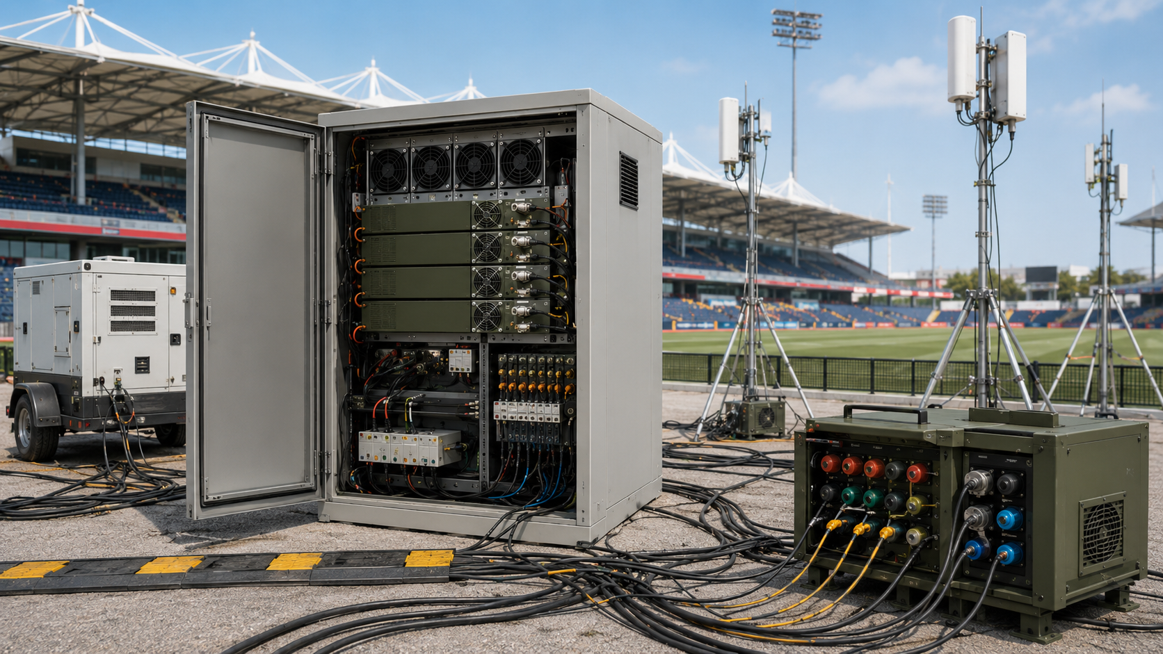
An RF PA current alarm can appear before stable RF output is reached. When it occurs immediately after power-on or enable, the first reaction is often to reject the PA module or increase a delay setting. Neither action should be treated as a root-cause decision until the startup event itself has been reconstructed.
A normal current reading after stabilization does not show what the PA saw at the alarm timestamp. The missing evidence may be the transient current, PA-terminal voltage, enable state, protection state, or the relationship between several of those signals on the same time base.
Before replacing the module or changing alarm settings, what must be measured at the startup event to separate a PA-side current fault from a power-path, sequencing, protection-state, or alarm-configuration problem?
1. Why Startup Current Must Be Separated from Steady-State Current
Startup current and steady-state current describe different operating conditions and should not be compared as if they were the same measurement.
Startup current is the current observed during the defined power-on or enable transition.
Steady-state current is the running current measured after the defined stabilization point under a stated operating condition, such as idle or a specified RF-drive and output condition.
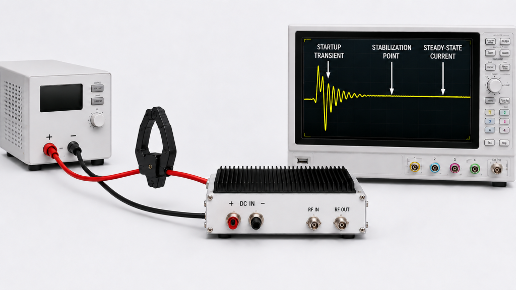
Depending on the PA and cabinet architecture, startup may include capacitor charging, bias activation, DC-DC converter startup, or auxiliary loads such as fans. Several PA channels may also begin drawing current within the same short interval.
These mechanisms are possible contributors to startup current, but none of them identifies the alarm source by itself.
A short current transient does not automatically prove that the PA module is defective. At the same time, a normal steady-state current value does not prove that the startup condition was acceptable.
For example, a PA may operate normally after stabilization while the startup event still exposes:
- a voltage drop in the local DC path;
- a power-supply current-limit response;
- simultaneous loading from several PA channels;
- an early or incorrectly sequenced enable command;
- a protection or monitoring state that has not yet reached its valid condition;
- a local problem associated with one harness, fuse, relay, connector, branch, or module.
The engineer therefore needs to know what happened when the alarm was generated, not only what the current became afterward.
A useful startup-event reconstruction should determine:
- when current started to rise;
- when the current alarm became active;
- what voltage the PA power terminals saw at that moment;
- whether the PA was already enabled;
- whether the required control and protection states were valid;
- whether one PA or several PAs were starting;
- whether the alarm cleared automatically, repeated, or remained latched.
A latched fault can preserve evidence of a short startup event after the original electrical condition has disappeared. The displayed alarm and the condition that triggered it therefore should not be treated as the same measurement.
2. How to Check an RF PA Current Alarm at the Event Timestamp
Before rejecting the PA, compare the electrical and control conditions on the same startup timeline.
Start with one defined PA channel
If possible, begin with a single PA channel under a defined startup condition.
Check whether the same alarm appears when that PA starts alone. Then repeat the test under the intended multi-module startup condition.
If the alarm appears only when several modules start together, simultaneous loading becomes an important test variable. It does not, by itself, prove that the shared DC bus is the root cause.
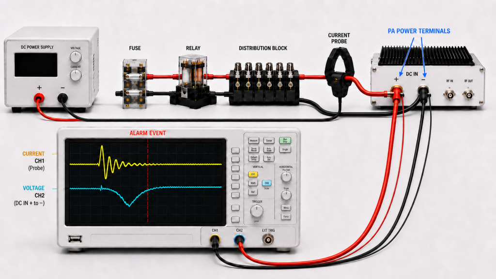
The comparison should determine whether the condition follows:
- the same PA module;
- the same channel;
- the same DC branch;
- the same harness or connector path;
- the same relay, fuse, or distribution output;
- or only a particular multi-module startup combination.
This helps separate a module-specific observation from a system-level interaction.
Measure voltage where the PA actually receives power
For startup current-alarm diagnosis, the relevant DC voltage is the voltage actually seen at the PA power terminals during the alarm event, not only the nominal or monitored voltage at the power-supply output.
The DC measurement point matters.
A stable voltage at the supply output does not prove that the PA terminals remained stable during the same startup event. Cable resistance, connectors, fuses, relays, harnesses, and distribution paths can produce a temporary voltage drop when current changes rapidly.
For a broader review of PA-terminal voltage, cable loss, and supply behavior under RF load, use the dedicated DC power-chain troubleshooting review.
Compare voltage and current on the same time base
A voltage disturbance and a current transient should be reviewed together.
If the supply enters a current-limit region, its voltage and regulation behavior depend on the supply design. The useful evidence is therefore the voltage and current recorded during the same startup event, preferably at the relevant PA power connection, rather than the current-limit label alone.
A current alarm that coincides with a PA-terminal voltage disturbance indicates that the electrical path should be investigated further. It does not, by itself, identify whether the root cause is the power supply, wiring, distribution hardware, protection logic, or PA.
Define how the transient current is measured
A startup-current peak is not meaningful without its measurement method.
The reported transient value can depend on:
- sensing method;
- current-probe or sensor bandwidth;
- controller or instrument filtering;
- sampling interval;
- capture window;
- trigger point;
- averaging or peak-detection method.
A fast oscilloscope capture, a filtered controller ADC, and slow power-supply telemetry may report different values for the same physical startup event.
For acceptance comparisons, the startup-current result should therefore be tied to a defined measurement method and sufficient time resolution.
If the RFQ or acceptance requirement specifies a maximum startup current, it should also define how that value is measured.
Treat multi-module startup as a defined test condition
In a multi-PA cabinet, simultaneous startup can change the voltage and current seen by individual channels.
Compare, where relevant:
- single-module startup;
- simultaneous multi-module startup;
- staged multi-module startup;
- PA-terminal voltage;
- per-channel current;
- alarm timestamp;
- branch identity;
- module S/N;
- enable state.
If one PA startup consistently affects another branch or channel, investigate that interaction separately rather than assuming its cause from the alarm alone.
If the symptom appears only when several modules share the same distribution path, continue with shared DC bus interaction rather than assuming the alarm source from startup timing alone.
Practical first review
Before replacing a PA module, ask:
- Does the alarm reproduce when this PA starts alone?
- Does it appear only during multi-module startup?
- Where is the DC voltage measured?
- What voltage does the PA actually see at the alarm timestamp?
- How was the startup-current transient measured?
- Is the capture resolution sufficient for the event duration?
- Does the controller reset or change state during startup?
- Does the condition follow one module, branch, harness, relay, fuse, or connector path?
- Does cold startup behave differently from a controlled restart?
- Does the alarm clear, repeat, or latch?
- Are the electrical and control records synchronized to the same event?
| What the Engineer Sees | First Question | What to Check | What It May Indicate |
|---|---|---|---|
| Current alarm appears only at startup | Does it disappear after the defined stabilization point? | Startup current, measurement method, and alarm timestamp | A startup transient, power-path condition, timing issue, or PA-side event needs to be separated |
| Alarm appears only when several modules start together | Does single-module startup pass? | Single vs multi-module startup, PA-terminal voltage, per-channel current | Simultaneous loading or shared-system interaction may be involved |
| Current alarm coincides with a measured voltage drop | Where was the voltage measured? | PA-terminal voltage and current on the same time base | Supply or distribution-path behavior requires investigation |
| Controller resets during startup | Does the controller share the affected DC path? | DC voltage, controller state, branch loading, startup timing | A system-level power interaction may be involved |
| Alarm repeats after reset | Is reset and fault-latch behavior defined? | Reset delay, alarm log, protection state | Recovery logic or the original fault condition may still be unresolved |
| Alarm appears on one channel only | Does the condition follow the branch or the PA? | Wiring, fuse, relay, connector, channel ID, module S/N | A local DC-path or module-specific condition may be involved |
| Alarm appears before required startup states are valid | When was PA enable accepted? | Enable timestamp and required startup states | Startup sequencing requires further verification |
3. How to Check Enable Timing Without Misdiagnosing the Current Alarm
An alarm that occurs during a startup transient is not automatically a false alarm.
It may be a valid response to a short over-current, under-voltage, or other protection condition even when the PA module itself is not defective.
The alarm result and the hardware diagnosis are two different conclusions.
Enable timing should therefore be checked as one part of the event, not used as a predetermined explanation.
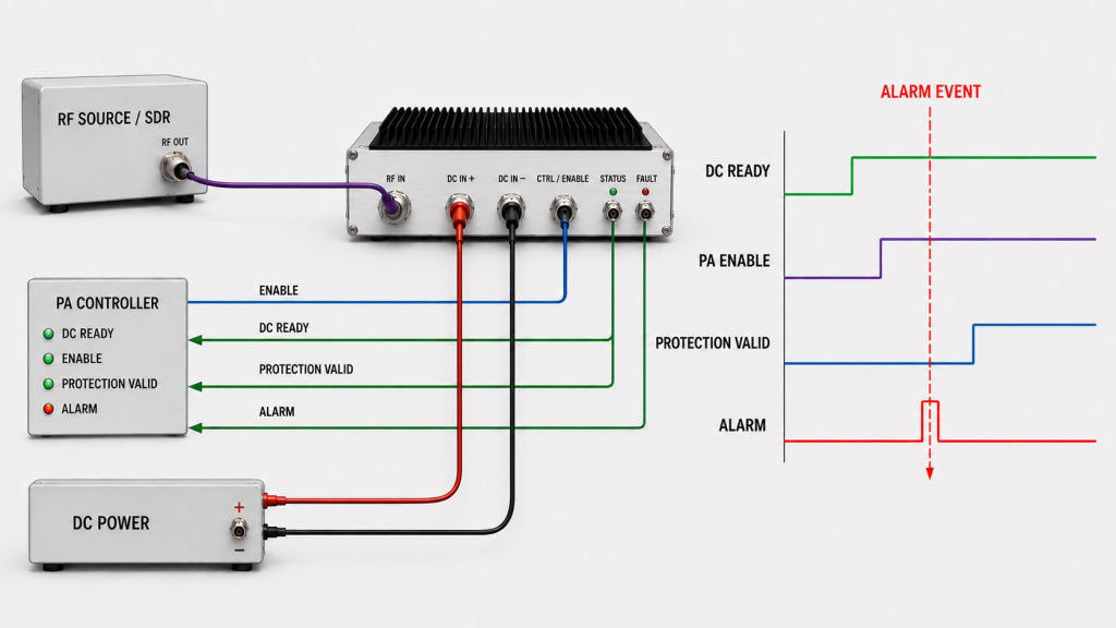
Relevant states may include:
- DC rail within the required operating range;
- controller interface ready;
- PA monitoring state valid;
- SDR or RF source in the required state;
- PA enable accepted;
- protection feedback valid;
- RF input drive valid, if required by the system sequence;
- alarm generated;
- fault reset or protection recovery.
There is no reason to assume that every RF system must use one universal startup order. The requirement is to define which states must be valid before the next action is allowed and then verify whether the actual event followed that logic.
A Power-On Sequence review is useful when the current alarm cannot be interpreted without reconstructing the wider startup timeline.
Several timing conditions can create diagnostic confusion:
- PA enable is accepted before the required DC condition is stable;
- the controller reads a protection state before that feedback is valid;
- several PA channels are enabled within the same short interval;
- reset is issued before the original condition has recovered;
- a latched historical fault is displayed as if it were a current active fault;
- one general controller alarm hides the channel-level source.
A useful startup log should therefore identify time, channel, state, and alarm type.
When command response, completion timing, timeout, or retry behavior becomes the main question, move the investigation to AT command timing rather than expanding the current-alarm diagnosis into a general control problem.
Do not change enable delays merely because the alarm occurred during startup. First verify whether the alarm timestamp actually correlates with an invalid electrical or control state.
4. What Evidence Is Needed Before Assigning the Root Cause?
A startup current alarm should be assigned to a root cause only after the relevant electrical, control, measurement, and identification data can be tied to the same event.
The RFQ or acceptance plan should separate startup current from steady-state current because the two measurements answer different questions.
It should also define the operating condition, measurement point, alarm definition, and expected recovery behavior.
| RFQ / Acceptance Item | What It Can Confirm |
|---|---|
| Startup current | Whether the measured startup current remains within the defined acceptance boundary using the stated sensing method, time resolution, and startup condition |
| Transient capture method | Whether startup current and PA-terminal voltage were recorded using a defined sensor, bandwidth or sampling condition, and time base suitable for comparing the alarm event |
| Steady-state current | Whether running current remains within the expected range after the defined stabilization point under the stated idle or RF-output condition |
| PA-terminal voltage trend | What DC voltage the PA actually sees during the alarm event |
| Single-module startup test | Whether the alarm can be reproduced with one defined PA channel |
| Multi-module startup test | Whether the defined simultaneous or staged startup condition changes or reproduces the alarm |
| PA enable timestamp | Where PA enable occurs relative to the other required startup states |
| Required source / SDR state | Whether the input-chain state required by the project is valid at the relevant time |
| Protection state | Whether the protection feedback used for the startup decision is valid and active, clear, or latched |
| Alarm definition / threshold / delay | Which sensed quantity and measurement point are used, what condition triggers the alarm, and what delay, filtering, latch, or recovery rule applies |
| Reset / retry behavior | Whether recovery is controlled and repeatable after the defined fault condition |
| Channel ID and module S/N | Whether the event can be tied to the delivered unit, branch, or channel |
| S/N-linked startup report | Whether the recorded startup dataset is traceable to the delivered unit and stated test configuration |
Alarm evidence needs more than a threshold number
A current-alarm threshold should not be evaluated only as a numeric setting.
Where relevant, the acceptance team should know:
- which quantity is being sensed;
- where that quantity is measured;
- the trigger level or condition;
- delay or filtering behavior;
- whether the alarm latches;
- what clears the alarm;
- what happens after reset or retry.
A threshold that reacts to an allowed startup transient can create an unnecessary rejection. A threshold that is too permissive can fail to identify an abnormal condition.
The correct alarm definition therefore depends on the stated operating and startup conditions, not on the alarm label alone.
Keep the evidence tied to the actual unit and test condition
When startup behavior forms part of delivery acceptance, traceability should follow a clear chain:
One Unit → One Serial Number → One Test Dataset → One Test Report → Traceable Acceptance Evidence
The report should also identify the startup configuration and measurement method when those conditions affect the result.
An S/N alone does not describe the test.
The evidence should state, as applicable:
- module quantity;
- actual DC input condition;
- single-module or multi-module startup method;
- branch or channel configuration;
- alarm definition;
- measurement point;
- transient-current measurement method;
- relevant control states.
Status information should likewise remain tied to a readable channel and timestamp. Where system feedback is the main limitation, RF PA status feedback can be reviewed separately.
FAQ
Does a current alarm during startup mean the RF PA is defective?
No conclusion should be made from the alarm alone.
The event may be associated with a PA-side condition, but power-path behavior, PA-terminal voltage, simultaneous loading, sequencing, alarm definition, protection state, and reset logic may also affect the result.
The diagnosis should follow synchronized evidence rather than the alarm label by itself.
What is the difference between startup current and steady-state current?
Startup current is measured during the defined power-on or enable transition using a stated transient measurement method.
Steady-state current is measured after the defined stabilization point under a stated operating condition, such as idle or a specified RF-drive and output condition.
They describe different operating states and should not be used interchangeably for acceptance.
What should be checked before replacing the PA module?
Check whether the condition follows the PA, channel, or DC branch; then compare PA-terminal voltage, startup-current data, alarm timestamp, enable and protection states, startup configuration, alarm definition, and reset behavior.
The purpose is to establish where the evidence points before assigning a root cause.
Why can a current alarm appear only when several PA modules start together?
Several PA channels starting within the same interval can change total current demand and the voltage seen at individual branches.
That makes simultaneous loading an important test condition, but it does not by itself prove that the shared DC bus is the root cause.
Compare single-module and multi-module tests using the same defined measurement points and time base.
What should the RFQ define after a startup current alarm?
Define the actual DC input range, startup-current measurement method, steady-state operating condition, PA-terminal voltage reference point, startup configuration, module quantity, enable timing, required control states, alarm definition, reset behavior, channel identification, and required S/N-linked evidence.
If RF output is part of the acceptance condition, also define the required output level and its measurement reference plane.
Conclusion
An RF PA current alarm during startup does not by itself prove that the PA is failing; the root cause should be assigned only after the startup event has been reconstructed.
The most useful evidence is synchronized: transient current measured with a defined capture method, voltage at the PA power terminals, alarm timestamp, channel identity, enable and protection state, and the stated single-module or multi-module startup condition.
Steady-state current should be compared only under a defined operating condition, and it cannot replace startup-event evidence.
Once these conditions are correlated, the engineering team can determine whether the evidence points toward a PA-side condition, a local DC path, shared-system interaction, startup sequencing, alarm configuration, or another verified cause without treating an initial hypothesis as a confirmed diagnosis.
When startup behavior forms part of RF PA approval, custom RF PA module review should use the actual project and acceptance conditions rather than steady-state RF output alone.
For RFQ review, provide the frequency range, target RF output and measurement reference plane, actual DC input range, module quantity, single-module and multi-module startup condition, PA-terminal voltage trend, startup-current waveform or peak with the measurement method and time resolution, PA enable timing, alarm definition and threshold, reset behavior, channel or branch ID, and required S/N-linked test evidence.