










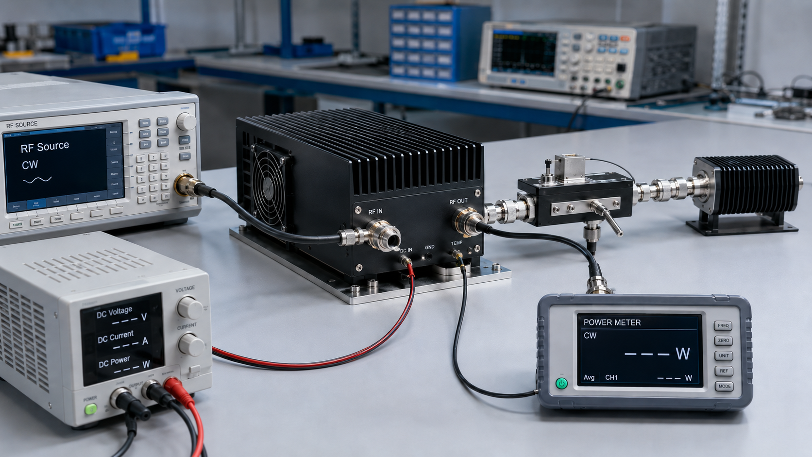
A higher wattage can make an RF PA look safer to buy. When one supplier quotes 100 W and another quotes 200 W, the larger number is easy to treat as more reliable RF power—but the comparison may not yet be valid.
For this review, reliable RF power is not a separate standardized RF power metric. It is a buyer-side acceptance boundary: the RF output that can be evaluated only after the relevant frequency, signal condition, reported power metric, measurement reference plane, operating duration, thermal state, DC condition, RF load, and required evidence are defined.
So before accepting the highest wattage in a C-UAS RFQ, which conditions must be fixed before two RF power claims can genuinely be compared?
1. Why Maximum Wattage Is Easy to Misread
Maximum RF power is attractive because it reduces a complex PA decision to one number.
A module described as 200 W appears stronger than one described as 100 W. But the wattage alone does not tell the buyer:
- at which frequency the value was measured;
- what signal or waveform condition was used, such as CW or a defined modulated signal;
- what power metric was reported, such as average power, peak power, or peak-envelope power where applicable;
- what RF input drive was applied;
- whether the result was measured at the PA output port or another defined reference plane;
- what DC input condition was used;
- what load or VSWR condition was present;
- whether the PA was cold or thermally stabilized;
- how long the output was maintained;
- whether protection remained inactive;
- whether the number came from one unit, a representative sample, or the delivered unit.
Before comparing a maximum-power claim, confirm both the signal condition and the reported power metric.
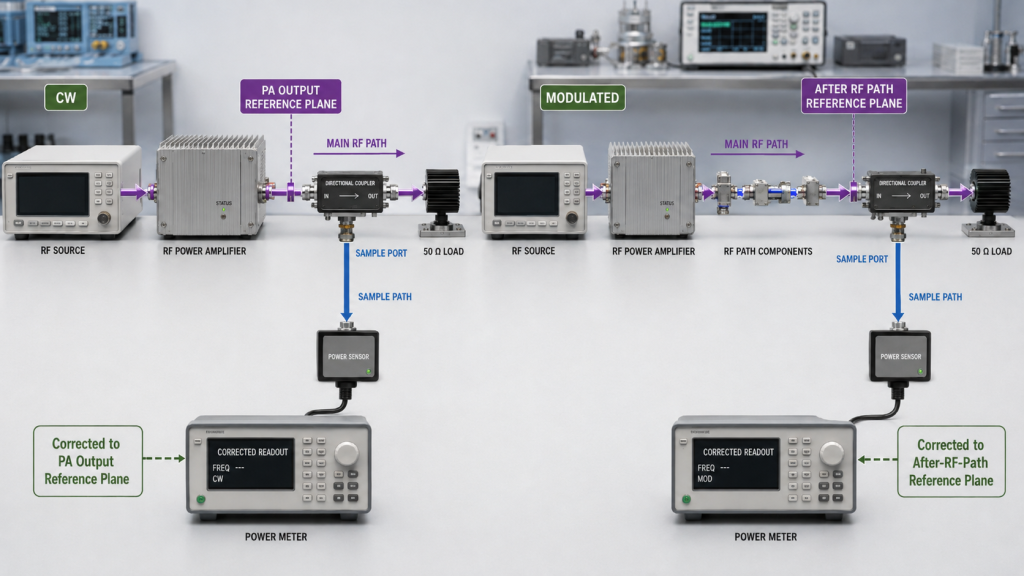
A CW test condition is not itself the same type of quantity as average, peak, or peak-envelope power. Likewise, a peak value from one waveform should not be treated as equivalent to an average-power requirement under another waveform.
A higher number may still be useful, but only after its measurement boundary is understood.
For broader C-UAS RF PA module selection, including frequency coverage, control, thermal conditions, RF output, and system requirements, use the project-level selection boundary before ranking modules by wattage.
2. What Conditions Must Define a Reliable RF Power Claim
Two RF power claims should not be treated as equivalent unless the conditions that materially affect the result are matched or their differences are explicitly identified and accounted for.
The exact conditions depend on the project, but the following boundaries commonly determine whether a quoted RF output can support selection or approval.
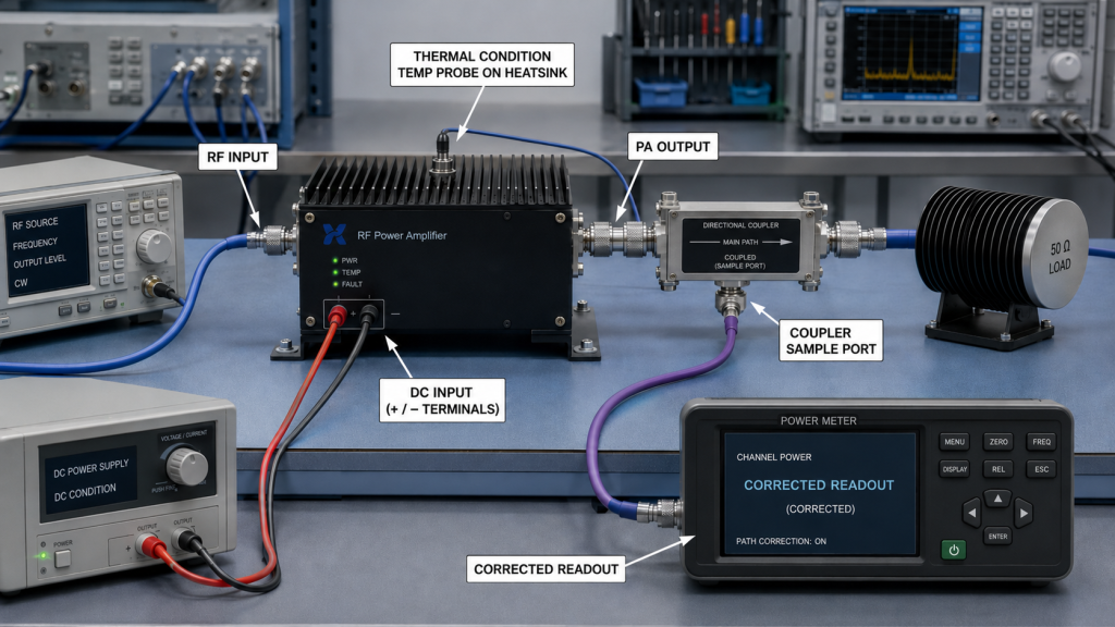
Frequency
A single favorable frequency point does not define full-band performance.
If the RF PA must operate across a frequency range, the buyer should define which frequency points or sweep must satisfy the power requirement.
The acceptance question is not:
What is the highest output anywhere in the band?
It is:
What output must be demonstrated at the required frequency points under the stated test condition?
Signal / waveform condition
The RFQ should define the signal condition used for the power requirement.
This may be:
- CW;
- a specified modulated waveform;
- a defined pulsed condition;
- or another project-specific signal condition.
Where a modulated or pulsed signal is used, the parameters that materially affect the result should also be stated.
The purpose is to prevent two power results measured under different waveforms from being treated as directly equivalent.
Reported power metric
The RFQ should separately state what power quantity is being reported.
Depending on the waveform and application, this may include:
- average RF power;
- peak RF power;
- peak-envelope power where applicable;
- or another explicitly agreed metric.
The signal condition and the reported power metric are related, but they are not interchangeable.
RF input condition
The required RF input drive should also be defined.
A quoted Pout without the corresponding input condition may not be sufficient for comparison, especially when two modules are driven at materially different Pin levels or operating points.
The RFQ should state the input condition that matters for acceptance rather than assuming that every reported output was achieved under the same drive.
Measurement reference plane
A reliable power claim is incomplete until the measurement reference plane is stated.
Power measured directly at the PA RF output port is not the same as power measured after:
- RF cable loss;
- connectors;
- filters;
- combiners;
- switches;
- couplers;
- or other installed RF-path components.
PA-port output and output at a defined antenna-side reference plane are different acceptance boundaries and should not be treated as the same measurement.
If the RFQ requires an antenna-side output condition, the RF-path loss and correction boundary should be defined separately rather than treating a PA-port measurement as the final system result.
Operating duration and thermal state
A short cold-state result does not define stabilized hot-state performance.
If the application requires sustained RF output, the acceptance condition should define:
- operating duration;
- duty cycle;
- cooling condition;
- relevant ambient or thermal condition;
- and the point at which the result is considered thermally stabilized.
The purpose is not to assume that output must decrease with time.
The purpose is to prevent a short measurement and a thermally stabilized measurement from being treated as equivalent evidence.
DC input condition
RF output should be tied to a defined module DC input condition.
The RFQ may need to state:
- nominal or project-defined Vdc range;
- allowed voltage variation;
- current capability;
- and the DC reference point when distribution-path loss is relevant.
A supplier result measured under one DC condition should not automatically be treated as proof of identical output under a materially different system supply condition.
RF load and VSWR condition
A nominal 50-ohm test is useful, but it does not describe every installed RF environment.
Where the project requires it, the RFQ should define:
- nominal load condition;
- allowable VSWR boundary;
- protection expectations;
- and whether the power requirement applies only at the PA port or through a defined installed RF path.
Detailed installed-load behavior should be verified separately rather than hidden inside a single reliable-power number. For that boundary, see dummy load testing and real antenna checks.
Representative application conditions
A fixed-site or high-security C-UAS installation can expose margins that a short bench result does not test—for example, longer operating periods, cabinet heat, installed RF-path loss, or repeated operating cycles.
These are project conditions to verify, not proof that a specific PA will fail after installation.
The RFQ should identify which conditions actually apply to the intended deployment instead of assuming that one generic field test represents every system.
3. What Evidence Makes an RF Power Claim Comparable
A power number becomes useful for approval only when the buyer can see the conditions behind it.
The goal is not to collect more screenshots.
The goal is to connect each important power claim to enough evidence that another engineer can understand what was actually measured and what the result can support.
| What the Buyer Sees | What May Be Missing | What to Check Before Approval | Why It Matters |
|---|---|---|---|
| Rated / maximum power claim | Signal condition and reported power metric | Defined waveform plus average, peak, PEP where applicable, or another stated metric | Different signal conditions and power metrics should not be treated as equivalent |
| High output at one frequency | Full-band behavior | Required frequency points or sweep | One favorable point does not define the required band |
| Power screenshot | Measurement reference plane | PA port, corrected reference plane, or defined antenna-side reference plane | The same instrument reading can represent a different acceptance boundary depending on where power is defined |
| Short full-power result | Duration and thermal state | Test time, duty cycle, cooling, stabilization condition | Cold and stabilized results answer different questions |
| Good result at nominal DC | Supply boundary | Project-defined Vdc condition and relevant DC measurement point | RF output can depend on the actual DC condition |
| Output into a dummy load | Installed-load boundary | Load, VSWR, protection expectation, RF path | Bench load and installed path are different test conditions |
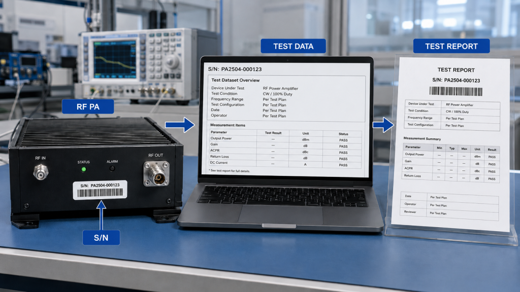
| Supplier test file | Unit identity | Module S/N and dataset linkage | Traceability identifies which unit the result belongs to |
| S/N-linked report | Complete test definition | Frequency, waveform, reported power metric, reference plane, thermal state, DC, load, duration | Traceability alone does not prove that the test condition was suitable for approval |
When the project requires full-band evidence rather than a single-frequency result, the detailed method belongs in a dedicated swept-frequency full-power RF PA test rather than being compressed into one wattage claim.
S/N linkage improves traceability, not the test definition
A serial-number-linked report is valuable because it connects the evidence to the delivered unit.
But S/N linkage does not replace a defined test condition.
The report should connect the delivered unit to the relevant:
- frequency;
- signal or waveform condition;
- reported power metric;
- RF input condition;
- measurement reference plane;
- operating duration;
- thermal state;
- DC condition;
- RF load;
- protection state;
- measured dataset.
For traceable acceptance, the evidence chain should be clear:
One Unit → One Serial Number → One Test Dataset → One Test Report → Traceable Acceptance Evidence
When a wider shipment checklist is required, S/N-linked test evidence should be reviewed together with the project-specific power requirement.
4. How to Specify Reliable RF Power in the RFQ
A useful RFQ should not ask only:
“What is your maximum RF output power?”
That question encourages suppliers to return a number without enough context for comparison.
Instead, define the conditions under which the output must be demonstrated.
RFQ Checklist
| RFQ Item | Customer Input Needed |
|---|---|
| Frequency requirement | Required band and key acceptance frequency points |
| Signal / waveform condition | CW or the defined modulated / pulsed waveform and relevant signal parameters |
| Reported power metric | Average, peak, PEP where applicable, or another explicitly agreed metric |
| Target RF output | Required output under the stated waveform and measurement condition |
| Measurement reference plane | PA output port, corrected reference plane, or defined antenna-side requirement |
| RF input condition | Required Pin, drive level, or other agreed input condition |
| Duty cycle | CW or stated operating duty cycle where applicable |
| Operating duration | Required test duration and stabilization point |
| Thermal condition | Cooling method and relevant thermal / ambient boundary |
| DC input | Project-defined Vdc range and relevant DC measurement point |
| RF load | Nominal load and required VSWR boundary |
| Protection behavior | Required alarm, foldback, shutdown, or recovery expectations where applicable |
| Test evidence | Required measured data, plots, logs, or report content |
| Traceability | Delivered module S/N linked to the test dataset and report |
| Quantity / acceptance scope | Which units require individual evidence |
The key is not to make every RFQ unnecessarily complex.
Only define the conditions that materially affect the required decision.
For example, if approval is based on PA-port CW output under a defined nominal load, there is no reason to create an antenna-side acceptance requirement that the project does not need.
If the system requires output at a defined antenna-side reference plane after an installed RF path, however, the measurement boundary and path-loss treatment must be defined before the required wattage can be interpreted correctly.
Do not let one condition substitute for another
Several common shortcuts can make two supplier claims look comparable when they are not:
- same wattage, different frequency;
- same wattage, different waveform;
- same wattage, different reported power metric;
- same wattage, different Pin;
- same wattage, different Vdc;
- same wattage, different measurement reference plane;
- same wattage, different thermal state;
- same wattage, different test duration;
- same wattage, different load condition.
A reliable-power requirement is therefore not “more conservative wattage.”
It is a better-defined acceptance boundary.
FAQ
What is the difference between maximum power and reliable RF power?
A maximum-power claim is a specified or reported RF output associated with a particular set of conditions. The number alone does not show whether those conditions match the buyer’s acceptance requirement.
In this article, reliable RF power means the output boundary a buyer can use for selection or approval after the necessary frequency, waveform, reported power metric, RF input condition, reference plane, duration, thermal, DC, load, and evidence conditions are defined.
It is an acceptance concept, not a separate standardized RF power metric.
Should C-UAS PA approval use PA-port power or antenna-side power?
Either can be valid if it matches the project requirement, but the measurement reference plane must be explicit.
PA-port output evaluates the amplifier at its RF output boundary.
Output at a defined antenna-side reference plane includes the effect of the specified installed RF path and therefore requires the relevant path-loss or correction boundary to be defined.
The two should not be treated as the same measurement.
What evidence should support a reliable RF power claim?
The evidence should identify both the unit and the test conditions behind the reported power result.
Depending on the project, that may include frequency, waveform, reported power metric, RF input condition, measurement reference plane, operating duration, thermal state, DC condition, RF load, protection state, measured output data, and module S/N.
S/N linkage provides traceability; the stated test conditions determine what the data can actually prove.
Conclusion
Reliable RF power should be defined as a project-specific acceptance boundary, not inferred from the largest wattage shown on a datasheet or test screenshot.
Before comparing or approving two RF power claims, define the conditions that materially affect the result: frequency, signal or waveform condition, reported power metric, RF input condition, measurement reference plane, operating duration, thermal state, DC input, RF load, and the evidence required to support the claim.
Maximum wattage can still be useful, but only when the buyer knows what that number actually represents and whether its test conditions match the intended acceptance boundary.
Once this reliable-power boundary is defined, a custom RF power amplifier module can be reviewed against the actual project requirement rather than against an isolated wattage claim.
For RFQ review, provide the required frequency points, signal or waveform condition, reported power metric, target RF output and measurement reference plane, RF input-drive condition, duty cycle, operating duration, thermal and cooling boundary, project-defined Vdc range, RF load or VSWR condition, protection expectations, quantity, and required S/N-linked report format.