










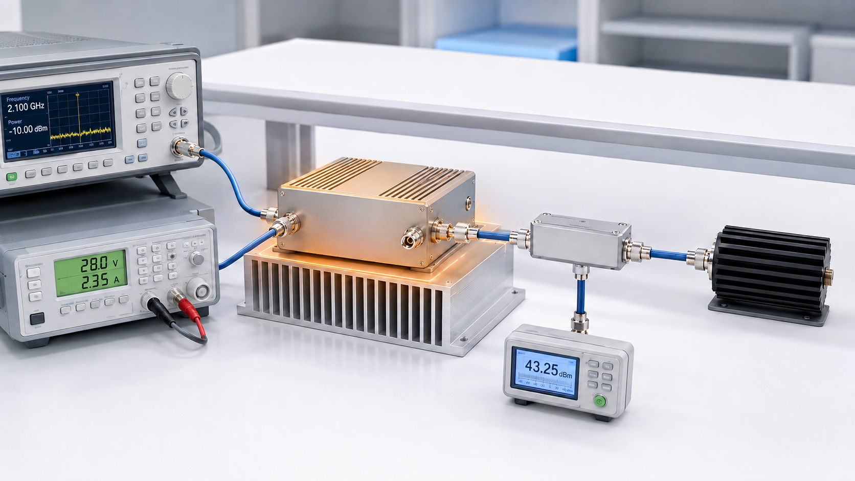
RF PA gain drift can remain hidden in cold-state test data. A module may show acceptable gain and output near startup, then lose usable margin after warm-up or thermal stabilization.
The first warning may not be a clear drop in output power. The PA may require more Pin, approach a current or temperature limit sooner, activate protection earlier, or lose margin only at one required frequency.
For RF Power Amplifier Modules, this creates a practical approval risk. One initial reading cannot prove that gain, corrected output, and available drive margin will remain acceptable during sustained operation.
RF PA gain drift is the change in measured power gain between two defined operating states. It must be calculated from actual Pin and corrected Pout at matching reference planes. Otherwise, source drift, voltage drop, compression, load change, protection activity, or measurement-path variation may be mistaken for DUT-related gain behavior.
A useful review must therefore determine:
- whether the initial and stabilized states are directly comparable;
- whether the measured change is larger than normal test-system variation;
- whether the result is fixed-Pin gain drift or constant-Pout required-drive change;
- and whether every project-defined output, electrical, thermal, load, and protection limit still passes.
The goal is not to demand zero change. It is to prove how much the gain changes, what caused the change, and whether the tested module still meets the agreed acceptance boundary.
1. What RF PA Gain Drift Means—and How to Calculate It
Measured RF power gain must use actual input power and corrected output power at defined reference planes.
| Metric | Calculation | Meaning |
|---|---|---|
| Measured power gain | Corrected Pout (dBm) − Actual Pin (dBm) | Gain at one defined operating state |
| Fixed-Pin gain drift | Gain at state 2 − Gain at state 1 | Change in measured gain while actual Pin remains inside its allowed tolerance |
| Constant-Pout required-drive change | Pin at state 2 − Pin at state 1 | Change in the input drive needed to maintain the same corrected Pout |
A positive fixed-Pin gain-drift result means measured gain increased. A negative result means measured gain decreased.
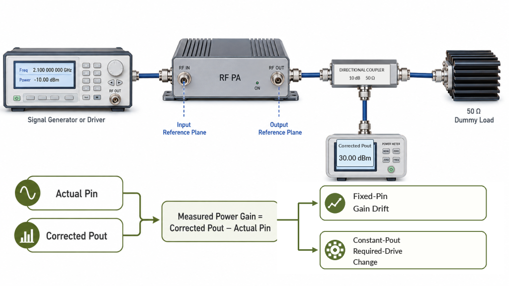
State 1 may be the defined initial state. State 2 may be a warm-up observation, thermal stabilization, the end of a continuous operating period, or another agreed test state.
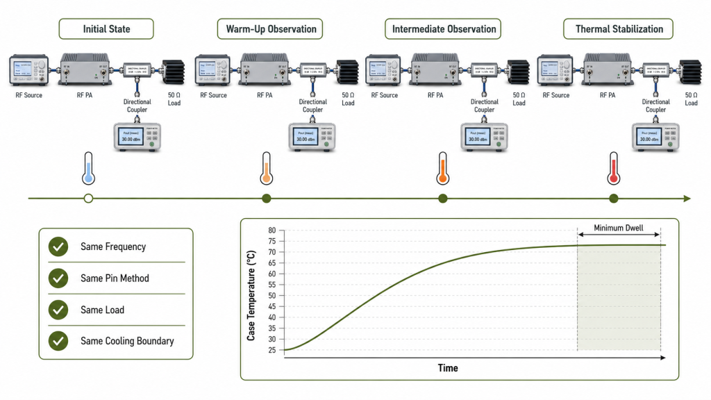
Both states must use the same:
- frequency;
- PA input reference plane;
- PA output reference plane;
- gain-test method;
- load boundary;
- duty cycle;
- cooling configuration;
- supply boundary;
- and measurement-correction method.
If supply, cooling, duty cycle, load, or another operating variable is intentionally changed, report the result as a separate sensitivity test. Do not combine it with the warm-up gain-drift value.
Gain Drift Is Not the Same as Pout Drift
Pout can change while measured gain remains stable.
If actual Pin and corrected Pout decrease by the same amount, calculated gain may show little change. The source or input path may be the first cause to investigate.
If Pin remains inside its defined tolerance while corrected Pout falls, measured gain will fall. The result may involve:
- DUT-related gain behavior;
- thermal change;
- compression;
- PA-terminal voltage reduction;
- load interaction;
- protection action;
- or measurement-system variation.
A Pout screenshot without matching Pin cannot prove gain drift.
Fixed-Pin and Constant-Pout Results Must Remain Separate
A fixed-Pin test measures gain and output change under a controlled input condition.
A constant-Pout test adjusts Pin to maintain the target output. Its main result is required-drive change.
If the same Pout requires more Pin after warm-up, available gain or source-drive margin has decreased. Report that change directly rather than hiding it inside a general gain-stability statement.
Both measurements may appear in one report, but they must be clearly labeled and interpreted separately.
2. How to Define Comparable Gain-Drift Test States
“Cold” and “hot” are not sufficient test definitions. The initial and stabilized states must be reproducible.
Define the Initial State
Before recording the baseline, specify:
- DUT preconditioning or power-off time;
- initial ambient or chamber temperature;
- temperature measurement location;
- instrument warm-up status;
- PA bias-settling time;
- RF-on delay before the first reading;
- load and cooling condition;
- and initial PA-terminal Vdc.
The signal generator, driver, power meter, sensor, and measurement path should complete their required warm-up before the DUT baseline is recorded.
Otherwise, source or meter stabilization may be mistaken for PA gain drift.
Use a Controlled Observation Sequence
A practical test sequence may include:
- a defined initial state;
- one or more warm-up observations;
- a minimum dwell time;
- thermal stabilization;
- and a recovery or restart check when required.
Use fixed observation intervals or clearly defined event-based points. Record elapsed time from the same starting condition.
A complete thermal-soak power measurement may define the wider temperature process. The gain-drift review should use that process to obtain directly comparable Pin, Pout, time, and temperature records.
Define Thermal Stabilization Independently
Do not use stable gain as the only proof that the DUT has reached thermal stabilization.
Prefer a rule based on temperature at a defined case or baseplate location. For example:
Thermal stabilization is reached after the minimum dwell time when the measured temperature changes by no more than the agreed value during the specified observation period.
The test record should identify:
- measured temperature;
- sensor location;
- minimum dwell time;
- observation period;
- allowed temperature-change rate;
- ambient or chamber temperature;
- and cooling boundary.
Gain and Pout stability may support the conclusion, but they should not be the only criteria used to end the test.
State the Operating Level
A small-signal time record cannot prove stability at the required output level.
When full-power evidence is required, repeat the selected frequency and observation states within a defined full-power RF PA test.
State whether the result comes from:
- small-signal fixed Pin;
- operating-drive fixed Pin;
- constant-Pout adjusted Pin;
- or a defined combination.
Do not compare a small-signal initial value with a compressed hot-state value and call the difference thermal gain drift.
3. How to Separate PA Gain Drift from Test-System and Operating Changes
Time-dependent measurements can change even when the DUT remains stable.
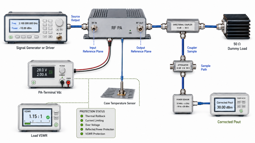
The test must show that the observed difference is not mainly caused by the source, measurement path, supply, load, cooling system, or protection response.
Verify Test-System Stability
Possible sources of apparent drift include:
- signal-generator or driver output change;
- temperature-dependent cable and connector loss;
- directional-coupler response;
- attenuator temperature coefficient;
- power-sensor zero or calibration shift;
- meter reading variation;
- and dummy-load heating or VSWR change.
Stabilize the test equipment before recording the DUT baseline.
When the expected drift is small, verify system repeatability with a reference-path check, repeated baseline readings, a known reference device, or another documented verification method.
A change comparable to normal test-system variation should not be reported as proven PA gain drift.
Control Actual Pin and Corrected Pout
A constant signal-generator setting does not guarantee constant Pin at the PA connector.
For every observation state, record:
- target Pin;
- allowed Pin tolerance;
- actual Pin at the defined input reference plane;
- and input-path correction where applicable.
Correct measured output back to one defined PA output reference plane. The correction record should identify:
- directional-coupler coupling factor;
- sample-path cable loss;
- attenuator value;
- sensor or meter correction;
- and any loss between the PA connector and the selected reference plane.
Use the same correction method for the initial and stabilized states. Do not combine mainline insertion loss and sample-path correction without showing the calculation direction.
Check Supply, Compression, Load, and Protection
Record PA-terminal Vdc and Idc during operation. The power-supply setting alone does not prove that the module receives the same voltage under hot-state load.
For the quoted 28 V operating route, confirm both PA-terminal voltage and available current capacity.
The two states must also use the same operating-drive definition. Identify whether the PA is working in:
- small-signal operation;
- linear large-signal operation;
- or a defined compressed state.
Establish the baseline into a specified 50 Ω dummy load or another agreed controlled load.
If gain changes while VSWR or reflected power also changes, repeat the comparison on the controlled load before assigning the result to the DUT.
Connect any thermal rollback, current limiting, or reflected-power protection event to the same time, frequency, Pin, Pout, Vdc, Idc, temperature, and load record.
Observed Change vs Required Confirmation
| Observed Change | Possible Cause | Required Confirmation |
|---|---|---|
| Gain and Pout fall at controlled Pin | DUT gain change, compression, voltage drop, thermal behavior, or protection | Compare Vdc, Idc, temperature, compression state, and protection log |
| Pout falls but measured gain remains stable | Lower Pin or changed measurement correction | Verify actual Pin, source path, and output correction |
| Constant Pout requires more Pin | Reduced available gain or drive margin | Record required-drive change and compare it with source capability |
| Gain changes while VSWR rises | Load interaction or protection response | Repeat on the specified controlled load |
| A small change repeats consistently | DUT behavior or repeatable system bias | Compare with test-system repeatability and uncertainty |
| Results vary substantially between runs | Setup, thermal, source, connector, or DUT repeatability issue | Repeat the complete controlled sequence |
4. Why Gain Drift Can Differ by Frequency
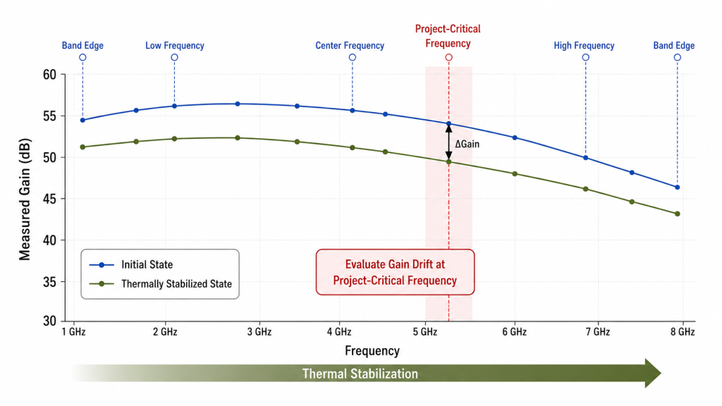
Gain drift may not be equal across the complete operating range.
One point may remain stable while another loses margin after warm-up. Frequency-dependent behavior may involve matching response, device gain, compression margin, current demand, thermal loading, load sensitivity, or protection margin.
Select test points from the project frequency plan. Include:
- exact priority frequencies;
- low, center, and high review points;
- required band-edge points;
- frequencies with lower initial margin;
- and known gain-ripple dips.
A center-frequency time record cannot prove gain stability across a wide operating range.
Compare the Same States at Every Frequency
Each selected frequency should use the same:
- initial-state definition;
- observation times;
- stabilization rule;
- Pin method;
- reference planes;
- supply condition;
- cooling boundary;
- and load.
Do not compare one frequency at the initial state with another after thermal stabilization.
Report Each Required Frequency
A full-band average can hide a critical point with larger negative drift.
For each required frequency, report:
- initial measured gain;
- stabilized measured gain;
- gain drift;
- elapsed time;
- direction of change;
- required-drive change where applicable;
- and acceptance result.
The broader RF PA frequency behavior under temperature should be reviewed when the project must determine why thermal margin differs across the operating range.
5. What Evidence Supports a Gain-Drift Acceptance Decision
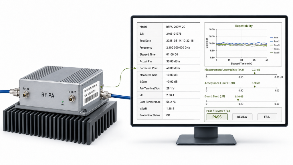
A reliable decision must connect the DUT, operating states, measurement method, repeatability, uncertainty, and acceptance rule.
Use a Focused Time-Series Record
| State | Elapsed Time | Frequency | Actual Pin (dBm) | Corrected Pout (dBm) | Measured Gain (dB) | ΔGain from Baseline (dB) |
|---|---|---|---|---|---|---|
| Initial state | Record | Project point | Record | Record | Calculate | 0.00 |
| Warm-up observation | Record | Same point | Record | Record | Calculate | Calculate |
| Intermediate state | Record | Same point | Record | Record | Calculate | Calculate |
| Thermal stabilization | Record | Same point | Record | Record | Calculate | Calculate |
| Recovery, if required | Record | Same point | Record | Record | Calculate | Calculate |
For each row, also record:
- PA-terminal Vdc and Idc;
- temperature value and measurement location;
- ambient or chamber condition;
- cooling condition;
- load and VSWR;
- protection state;
- test method;
- and correction record.
Demonstrate Repeatability and Measurement Confidence
One test run may not be enough when the measured change is close to the acceptance limit.
The report should state:
- number of repeated runs;
- reset or recovery condition between runs;
- maximum run-to-run variation;
- test-system repeatability;
- and whether the direction and magnitude of the change repeat.
Evaluate the reported drift against demonstrated system variation and any agreed measurement uncertainty.
A measured change of −0.20 dB should not automatically be treated as proven DUT drift when normal test variation is of similar magnitude.
The acceptance process may use an uncertainty value, repeatability data, an agreed guard band, or another project-approved decision rule. The report should identify the selected rule.
Define the Drift Metric Before Testing
“Maximum gain drift” can refer to different results.
The RFQ or test plan should define one or more of the following:
- stabilized drift from the initial baseline;
- maximum absolute drift;
- maximum negative drift;
- peak-to-peak gain excursion;
- constant-Pout required-drive change;
- recovery offset after cool-down;
- or cycle-to-cycle hysteresis.
Do not select the most favorable metric after collecting the data.
Link Evidence to the Tested Unit
The report should include:
- model and module S/N;
- hardware or configuration revision;
- report number and version;
- test date;
- equipment and correction references;
- tested frequencies;
- test method;
- initial-state definition;
- stabilization rule;
- repeatability information;
- uncertainty or guard-band method;
- and final pass, review, or fail result.
Do not combine a gain curve from one unit with thermal, output, or protection evidence from another when delivered-unit verification is required.
RFQ Checklist for RF PA Gain Drift
“Stable gain required” does not define the measurement or acceptance boundary.
Project Output Boundary
Provide:
- required frequency range and exact target points;
- minimum corrected Pout;
- nominal Pin at the PA input connector;
- maximum available source or driver Pin;
- allowed Pin tolerance;
- and PA input and output reference planes.
Test Method
Define:
- fixed-Pin, constant-Pout, or combined test method;
- small-signal or operating-drive condition;
- output-correction requirements;
- instrument warm-up requirement;
- DUT preconditioning;
- RF-on delay before the initial reading;
- and test-system verification method.
Thermal and DC Boundary
Provide:
- PA-terminal voltage and current capacity for the quoted 28 V route;
- duty cycle;
- minimum operating duration;
- observation intervals;
- stabilization rule;
- temperature measurement location;
- ambient or chamber condition;
- and cooling or installation boundary.
Load and Protection Boundary
Define:
- controlled dummy-load condition;
- installed-path test requirement, if applicable;
- VSWR or reflected-power limit;
- allowed protection behavior;
- and recovery or repeated-cycle requirement.
Evidence and Acceptance
Specify:
- required number of test runs;
- measurement-uncertainty requirement;
- repeatability requirement;
- selected drift metric;
- acceptance limit;
- decision guard band;
- S/N-linked report format;
- and whether the evidence must represent a sample, batch, or delivered unit.
The supplier should confirm the tested points, measurement methods, correction calculation, observation times, stabilization method, load and cooling conditions, repeatability evidence, uncertainty rule, and recorded DC, thermal, VSWR, and protection data before the test plan is approved.
Conclusion
RF PA gain drift cannot be proven from lower hot-state output alone.
Calculate measured power gain from actual Pin and corrected Pout at matching reference planes. Keep the operating and measurement boundaries constant. Separate fixed-Pin gain drift from constant-Pout required-drive change.
Verify test-system stability before assigning a small time-dependent change to the DUT. Evaluate the result against repeatability, measurement uncertainty, and the project’s decision guard band.
Approve the module only when the selected drift metric and every applicable output, drive, electrical, thermal, load, and protection limit remain satisfied.
RF SKYPOWER can support early engineering review for RF PA gain-drift requirements. Send the target frequencies, selected test method, nominal and maximum Pin, minimum corrected Pout, 28 V PA-terminal voltage and current boundary, duty cycle, stabilization rule, cooling condition, load or VSWR limit, drift metric, acceptance limit, and required S/N-linked report format.
The review can then determine whether the measured change remains acceptable, requires a better-controlled test, or indicates a problem in the DUT, test system, input path, DC supply, load, cooling boundary, or protection response.