










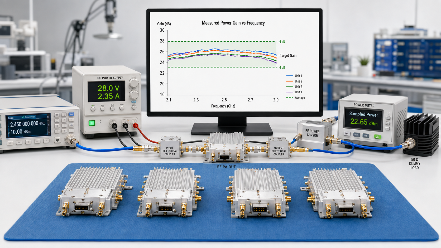
RF PA gain tolerance can look precise in an RFQ and still be impossible to defend during batch acceptance. A narrow gain window may appear to guarantee consistency, yet it proves little if Pin is not controlled at the same reference plane, Pout corrections change, thermal states differ, or measurement uncertainty consumes most of the allowed limit.
This creates a dangerous approval illusion. Every serial number may receive a clean pass or fail result, while the test system cannot reliably separate real unit-to-unit variation from source drift, cable loss, correction error, load change, or warm-up behavior.
The result can fail in either direction. A compliant module may be rejected because of measurement variation. A real batch outlier may also pass because averages, retests, or mismatched conditions hide the difference.
For batch delivery of RF Power Amplifier Modules, the most important question is therefore not:
What gain tolerance number should we choose?
The more useful question is:
Can the proposed acceptance window actually be measured, repeated, and enforced across every tested unit?
A defensible answer requires more than Gmin, Gmax, or a target ± tolerance. The project must define actual Pin, corrected Pout, reference planes, frequency-specific limits, hardware and configuration boundaries, operating state, measurement uncertainty, sampling rules, and the action taken when a result falls near or outside the limit.
This article explains how to turn RF PA gain tolerance from a vague supplier promise into a measurable batch-acceptance boundary.
1. What RF PA Gain Tolerance Must Define
RF PA gain tolerance defines the allowed variation of measured power gain around an agreed target or within specified lower and upper limits under defined test conditions.
A separate batch-spread limit may also control the observed difference between tested units at the same frequency and operating state.
A phrase such as “stable gain required” does not define an acceptance boundary. It does not identify:
- the target frequency;
- the gain-test method;
- the input and output reference planes;
- the operating state;
- the allowed unit deviation;
- or the pass/fail rule.
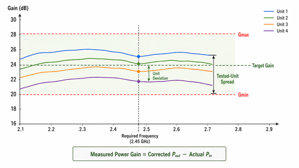
Gain Tolerance Is Not Gain Flatness
Gain flatness describes how the gain of one amplifier changes across frequency.
Gain tolerance defines how much measured gain variation the project will accept at a specified frequency and test state.
A module may have acceptable gain flatness but still fall outside the required gain window. A batch may also show a narrow spread at one frequency and a wider spread at a band edge or project-critical point.
Gain Tolerance Is Not Gain Drift
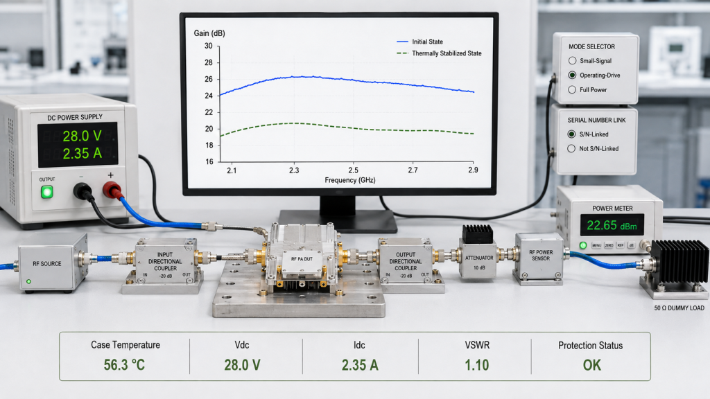
Gain drift describes how the same unit changes between two defined operating states. Typical examples include the initial state and thermal stabilization.
Batch gain tolerance compares different units under matching conditions.
When the batch test uses a stabilized hot state, each unit must reach the same defined state before comparison. The method for separating DUT-related change from source, supply, load, and measurement variation is explained in RF PA gain drift.
Gain Tolerance Is Not Output-Power Tolerance
Measured gain and output power are related, but they are not interchangeable.
Two modules may produce similar Pout because the test system applies different Pin. Their measured gain may still differ.
Two modules may also show similar measured gain but produce different Pout because of different Pin, compression, DC conditions, or output corrections.
Projects that control delivered-unit Pout should define batch RF power tolerance separately.
One Sample Does Not Define the Acceptance Window
A prototype can confirm that the design route is capable of meeting the target. It cannot define the distribution of later production units by itself.
The project must decide whether the approved sample establishes:
- a nominal target;
- a minimum acceptable result;
- a maximum acceptable result;
- or only an early engineering reference.
A separate review of RF PA batch gain consistency explains why one sample cannot prove the gain distribution of a delivered batch. The current page focuses on the limits used to judge the tested units.
RF PA Gain Tolerance Metrics
| Metric | Calculation or Boundary | What It Proves |
|---|---|---|
| Measured power gain | Corrected Pout − Actual Pin | Gain of one unit at one defined test point |
| Unit deviation | Measured power gain − Agreed target gain | Distance from the project target |
| Acceptance window | Gmin to Gmax | Whether one tested result passes |
| Observed tested-unit spread | Highest measured gain − Lowest measured gain | Observed range among tested units at one frequency and test state |
| Tested-unit average | Sum of measured gains ÷ number of tested units | Center of the tested results, not outlier status |
The tested-unit average must not override a failed unit.
The observed tested-unit spread also has limits. It describes only the units included in the comparison. It does not prove:
- the distribution of untested units;
- long-term process capability;
- later production lots;
- or replacement-unit behavior.
A useful acceptance rule should therefore define both:
- the allowed result for each tested unit;
- the allowed spread or distribution rule for the tested group.
2. How to Build Comparable Gain Data Across Delivered Units
Batch gain data is only useful when every tested unit uses a common measurement boundary.
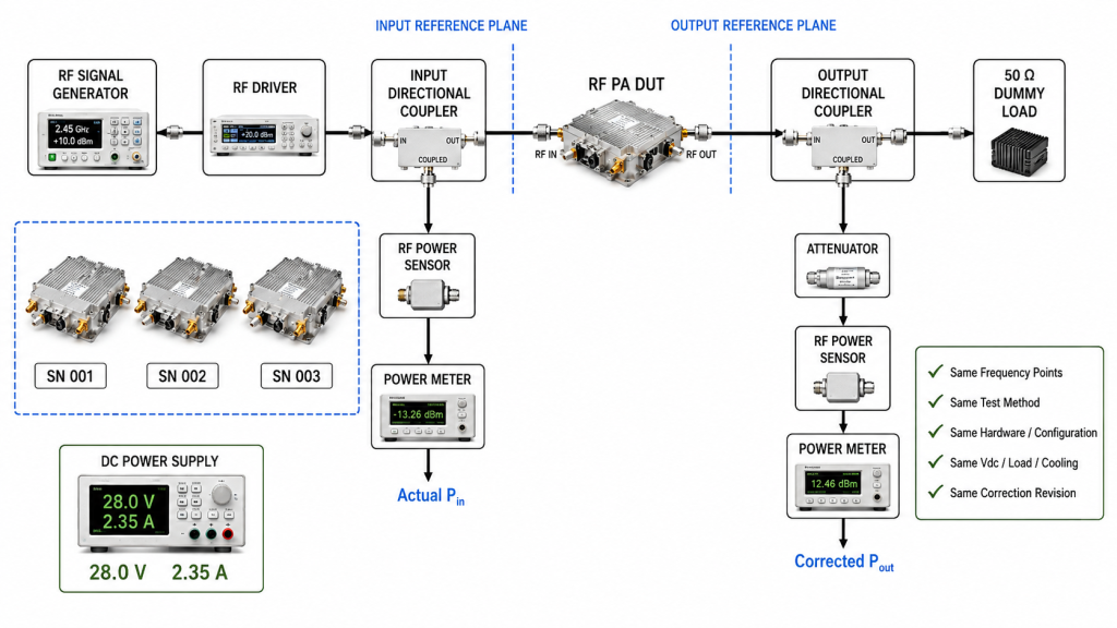
The basic calculation is:
Measured power gain (dB) = Corrected Pout (dBm) − Actual Pin (dBm)
Both values must belong to the same unit, frequency, operating point, and defined reference planes.
Define the Input Reference Plane
The report should state where Pin is defined.
Possible boundaries include:
- signal-generator output;
- driver output;
- cable input;
- PA input connector;
- or another project-defined point.
For batch acceptance, actual Pin should normally be measured at the PA input reference plane or corrected to that plane.
A constant generator setting does not prove constant PA input power. Driver behavior, cable loss, connector condition, attenuation, and source drift can change the power that reaches each amplifier.
The test plan should define:
- target Pin;
- allowed Pin variation;
- actual measured Pin;
- input-path correction;
- and whether Pin remains fixed or is adjusted.
If Pin is adjusted to maintain constant Pout, the principal result is required-drive variation. It should not be reported as fixed-Pin gain tolerance.
Define the Output Reference Plane
Corrected Pout must use one agreed output reference plane.
The correction record may include:
- directional-coupler factor;
- sample-path cable loss;
- attenuator value;
- sensor or meter correction;
- connector or adapter loss;
- and selected reference-plane loss.
The report should show the calculation direction.
Do not combine sample-path correction with mainline insertion loss unless the test method clearly requires both.
Every tested unit must use the same output correction method and correction revision.
Use the Same Frequency Points
A center-frequency result cannot prove batch gain tolerance across a wide operating range.
Select frequencies from the real project plan, including:
- required operating points;
- low, center, and high review points;
- specified band edges;
- points with lower design margin;
- and frequencies where prior testing shows greater variation.
Every unit should use the same frequency list.
Do not average results across different frequencies to make one unit pass. Each required frequency should be judged against its own target or acceptance window unless the RFQ defines another method in advance.
Control the Hardware and Configuration Boundary
Do not combine unlike units in one gain-tolerance statistic.
The acceptance plan should identify:
- model number;
- hardware revision;
- matching-network revision;
- control or firmware configuration, when relevant;
- approved BOM state;
- connector configuration;
- and cooling-interface configuration.
Units from different hardware revisions, matching networks, firmware states, or approved BOM boundaries should not share one tolerance statistic unless the RFQ explicitly permits the comparison.
The plan should also state whether the gain limit applies:
- within one production lot;
- across several production lots;
- to later repeat orders;
- and to replacement units.
Use One Gain-Test Method
The batch comparison should use one defined method, such as:
- small-signal gain;
- fixed operating Pin;
- constant-Pout required drive;
- or another project-defined method.
Do not compare fixed-Pin data from one unit with adjusted-Pin data from another.
Small-signal and operating-drive results may both be useful, but they should remain separate datasets.
Verify the Test System
The test system must be stable enough to resolve the requested tolerance.
Before interpreting unit-to-unit differences, confirm:
- instrument warm-up;
- source repeatability;
- driver stability;
- cable and connector condition;
- coupler and attenuator verification;
- sensor or meter verification;
- load condition;
- and correction-file revision.
Repeatability data should show whether the observed unit difference is larger than normal test-system variation.
DC, thermal, cooling, load, duty, and protection conditions must also remain comparable. Section 4 explains how to choose those operating boundaries.
3. How to Set the Batch Gain Acceptance Window
There is no universal RF PA gain tolerance that fits every project.
The acceptable window depends on:
- available source or SDR drive;
- target corrected Pout;
- calibration capability;
- required frequencies;
- compression margin;
- DC margin;
- thermal condition;
- installed RF path;
- replacement requirements;
- and measurement capability.
Start with the System Margin
The gain window should support the required RF-chain result.
If gain is too low, the source or driver may not provide enough Pin to reach target output.
If gain is too high, the same source setting may drive the PA farther into compression. The system may then require additional attenuation or calibration.
The project should review:
- nominal available Pin;
- maximum safe Pin;
- target corrected Pout;
- minimum acceptable gain;
- maximum acceptable gain;
- and remaining drive margin.
The tolerance should not be selected only because one sample achieved it.
Choose the Acceptance Format
A project may use one or more of the following formats.
Absolute Gain Window
Every tested unit shall remain between Gmin and Gmax at each required frequency.
This method is practical when the project already knows the acceptable gain range.
Target With Allowed Deviation
Every tested unit shall remain within the agreed target gain and specified positive and negative deviations.
The positive and negative limits do not have to be equal.
A project may accept more positive variation than negative variation, or the reverse, depending on drive and output margin.
Observed Tested-Unit Spread
The difference between the highest and lowest measured gain among the tested units shall not exceed the agreed spread at each required frequency.
Spread alone is not enough.
A tested group may have a narrow spread while every unit sits below the required minimum. The average may also look acceptable while one outlier fails.
The project should combine tested-unit spread with unit-level limits.
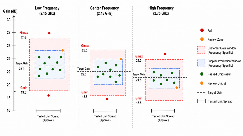
Set Limits by Frequency
One tolerance value across a wide range may be too simple.
A broadband PA may have:
- different nominal gain by frequency;
- lower margin at a band edge;
- stronger compression at one point;
- or higher measurement uncertainty in part of the range.
The RFQ may therefore define separate:
- target gains;
- Gmin and Gmax values;
- allowed deviations;
- and tested-unit spread limits;
for each required frequency or frequency block.
Do not use a cross-frequency average to override a failed point.
Do not use a tested-unit average to override a failed serial number.
Account for Measurement Uncertainty
A narrow tolerance is only useful when the test system can resolve it.
The acceptance method should consider:
- demonstrated repeatability;
- relevant measurement uncertainty;
- correction-factor uncertainty;
- run-to-run variation;
- and verification status.
When the allowed gain tolerance is close to the demonstrated measurement uncertainty, the project should define a decision rule before batch testing.
Possible methods include:
- a guard band;
- repeated measurements near the limit;
- an engineering-review zone;
- a conservative acceptance boundary;
- or another agreed uncertainty-aware rule.
Do not choose the decision rule after seeing the results.
Use a Guard Band When Needed
A guard band creates separation between the customer specification boundary and the production acceptance boundary.
A project may define:
- the customer gain window;
- a narrower supplier production window;
- and a review zone near either edge.
The exact guard band depends on the agreed risk and demonstrated measurement uncertainty.
The report should identify the final state as:
- pass;
- review;
- retest required;
- or fail.
Do Not Let Calibration Hide Undefined Variation
A control system may compensate for some gain difference. That does not mean any gain spread is acceptable.
Before relying on calibration, confirm:
- available adjustment range;
- adjustment resolution;
- channel-specific storage;
- source-drive margin;
- effect on compression;
- replacement procedure;
- and field recalibration requirements.
Gain tolerance should reduce calibration and maintenance risk. It should not transfer an undefined production variation to the integrator.
4. Which Operating State Should Control Acceptance?
The RFQ must identify which operating state controls the gain decision.
Small-signal, operating-drive, full-power, cold-state, and hot-state results answer different questions.
Small-Signal Screening
Small-signal gain is useful for:
- basic frequency-response review;
- production screening;
- early comparison;
- and detection of obvious unit differences.
It does not automatically prove behavior near the project output requirement.
A project may use small-signal data as an informational or screening result while using another state for final acceptance.
Operating-Drive or Full-Power Acceptance
Operating-drive or full-power gain is more relevant when the project must approve actual high-output behavior.
At higher output, units may separate because of:
- compression;
- current demand;
- PA-terminal voltage drop;
- heat buildup;
- load interaction;
- or protection margin.
The project does not always need a complete small-signal and full-power acceptance program for every point.
A practical plan may use:
- small-signal screening across a wider frequency set;
- operating-drive checks at project-critical points;
- and full-power verification where output acceptance requires it.
The RFQ should state which result is informational and which result controls acceptance.
Initial or Thermally Stabilized State
Cold-state gain should not be mixed with stabilized hot-state gain.
The test plan should define:
- DUT preconditioning;
- initial ambient or chamber condition;
- RF-on delay;
- minimum dwell time;
- temperature measurement location;
- stabilization rule;
- and observation time.
If hot-state gain controls acceptance, each unit must reach the same defined thermal state.
Stable gain alone should not prove thermal stabilization. Use a temperature-based rule at a defined case or baseplate location.
Controlled Load or Installed RF Path
A controlled 50 Ω load provides a repeatable PA baseline.
The installed path may introduce:
- feeder loss;
- connector loss;
- adapters;
- mismatch;
- reflected power;
- and frequency-dependent loading.
If the project requires installed-path evidence, define it separately from the controlled-load baseline unless the installed path is the agreed acceptance reference.
Do not compare one unit on a dummy load with another through a feeder or antenna path.
Protection-Active States
If thermal rollback, current limiting, reflected-power protection, or another protective action occurs, identify that state in the same record as:
- frequency;
- actual Pin;
- corrected Pout;
- measured power gain;
- Vdc;
- Idc;
- temperature;
- load;
- reflected power or VSWR;
- and elapsed time.
Do not mix a protection-active result with an unprotected baseline.
The RFQ should state whether a protection-active state is:
- allowed;
- reviewed separately;
- or an automatic failure under the specified test condition.
5. What Evidence Proves the Tested Batch Passed?
A valid batch claim needs unit-level evidence and a clear batch decision rule.
A generic datasheet cannot prove that a specific serial number passed the agreed gain window.
The broader RF PA acceptance evidence should connect gain results with output, voltage, current, temperature, load, protection, and report identity.
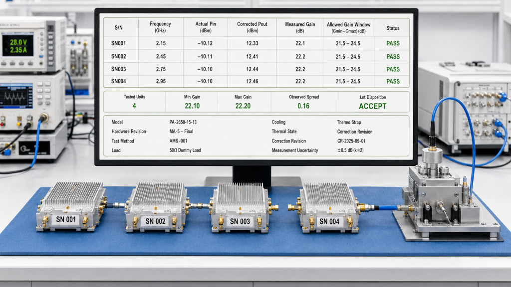
Unit-Level Gain Record
| S/N | Frequency | Actual Pin | Corrected Pout | Measured Power Gain | Allowed Window | Deviation From Target | Acceptance |
|---|---|---|---|---|---|---|---|
| Unit 1 | Record | Record | Record | Calculate | Gmin–Gmax | Calculate | Pass / Review / Fail |
| Unit 2 | Record | Record | Record | Calculate | Gmin–Gmax | Calculate | Pass / Review / Fail |
| Unit 3 | Record | Record | Record | Calculate | Gmin–Gmax | Calculate | Pass / Review / Fail |
The report or table header should also define the common test boundary:
- model and hardware revision;
- approved BOM or configuration state;
- input and output reference planes;
- gain-test method;
- operating state;
- PA-terminal Vdc;
- load and cooling condition;
- duty cycle or duration;
- temperature value and location;
- correction revision;
- measurement uncertainty;
- and decision rule.
Batch Summary and Sampling Rule
A batch summary may report:
- lot identity;
- number of delivered units;
- number of tested units;
- minimum measured gain;
- maximum measured gain;
- tested-unit average;
- observed tested-unit spread;
- number of passes;
- number of reviews;
- number of failures;
- and final lot disposition.
The summary should not hide the S/N-linked results of tested units.
The project must also define whether acceptance uses:
- 100% unit-level testing;
- a fixed sample quantity;
- a percentage of the lot;
- or another approved sampling plan.
When unit-level acceptance is required, every delivered unit should have an S/N-linked result.
When sampling is used, the evidence proves only:
- the status of the tested units;
- and the agreed lot-level decision.
It does not prove the individual status of every untested module.
A sampling plan should define:
- lot size;
- sample size;
- unit-selection method;
- acceptance and rejection rule;
- and expanded-inspection trigger.
Retest and Lot Disposition
The RFQ should define what happens when a result falls outside the gain window.
Possible actions include:
- setup verification;
- one controlled retest;
- repeated measurement after a defined thermal reset;
- expanded lot inspection;
- engineering review;
- rework followed by complete retest;
- unit replacement;
- or lot rejection.
Avoid unlimited retesting until a passing value appears.
The record should preserve:
- original result;
- reason for retest;
- any changed condition;
- retest result;
- and final disposition.
Replacement Acceptance
A replacement module should meet the same relevant boundary as the installed population.
The project may require:
- the same model and approved revision;
- compatible target-frequency gain;
- compatible operating-drive behavior;
- matching control and protection configuration;
- and an S/N-linked report.
The RFQ should state whether the original tolerance applies only within one production lot or also across later replacement orders.
RFQ Checklist for RF PA Gain Tolerance
“Stable gain,” “good consistency,” and “tight tolerance” are not measurable RFQ requirements.
Gain Window
Define:
- target gain or Gmin/Gmax;
- allowed positive and negative deviation;
- maximum observed tested-unit spread;
- frequency-specific limits;
- and the rule for every tested unit.
Measurement Boundary
Define:
- input and output reference planes;
- actual Pin requirement;
- corrected Pout method;
- measured power-gain calculation;
- correction revision;
- and test-system verification.
Operating State
Define:
- required frequency points;
- small-signal, operating-drive, or full-power method;
- initial or stabilized thermal state;
- PA-terminal supply condition;
- load and cooling boundary;
- and allowed protection behavior.
Batch Rule
Define:
- model, revision, configuration, and lot boundary;
- batch quantity;
- 100% testing or sample size;
- acceptance and rejection rule;
- expanded-inspection trigger;
- and replacement-unit requirement.
Evidence and Decision
Require:
- S/N-linked results for all tested units;
- target and allowed window;
- actual Pin and corrected Pout;
- measured power gain and deviation;
- measurement uncertainty or guard-band rule;
- retest history;
- and final unit and lot disposition.
A stronger RFQ statement is:
Provide S/N-linked measured power-gain data for each tested RF PA module at the agreed frequency points. Calculate gain from actual Pin and corrected Pout at matching reference planes. Use the same approved hardware configuration, test method, operating state, supply, load, cooling, and correction boundary for all compared units. Apply the agreed unit-level gain window, tested-unit spread limit, uncertainty rule, sampling plan, and retest procedure before batch approval.
Conclusion
RF PA gain tolerance is not a universal brochure number. It is a project-defined acceptance boundary.
The project should define:
- measured power gain;
- target or Gmin/Gmax;
- allowed unit deviation;
- observed tested-unit spread;
- frequency-specific limits;
- and the operating state that controls acceptance.
Every compared unit must use the same approved hardware and configuration boundary. The test must also use matching frequencies, Pin and Pout reference planes, measurement method, supply, thermal state, cooling, load, and correction method.
Small-signal data can support screening. Operating-drive or full-power evidence should control acceptance when actual high-output behavior matters. Initial and thermally stabilized results should remain separate.
The acceptance plan should also define measurement uncertainty, guard bands, sampling, retesting, lot disposition, and replacement-unit rules before the batch results are reviewed.
RF SKYPOWER can support an early batch-gain review. Provide the target frequencies, gain window, Pin and corrected Pout boundaries, operating state, load and cooling conditions, batch acceptance rule, and required S/N-linked evidence.
The review can identify whether the requested tolerance is measurable and compatible with the available drive, output margin, and batch-delivery requirements.