








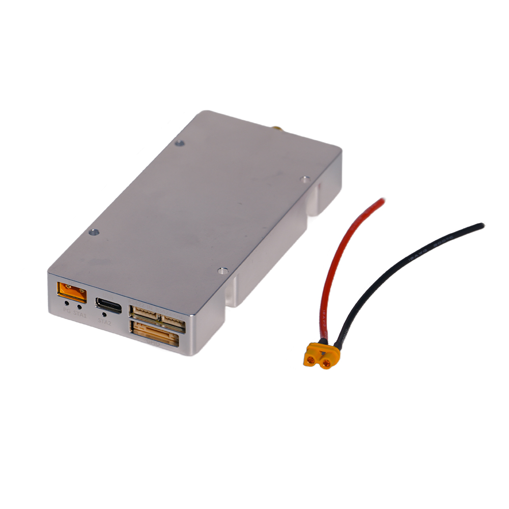
CUSTOM IQ / CASCADING ROUTE
A stronger starting point when the system needs custom IQ loading, up to 200 MHz real-time bandwidth, RS422 AT-command control, and documented multi-unit cascading.


High-performance systems engineered for consistent, dependable operation under critical conditions.
See It in Action
High-performance systems engineered for consistent, dependable operation under critical conditions.
See It in Action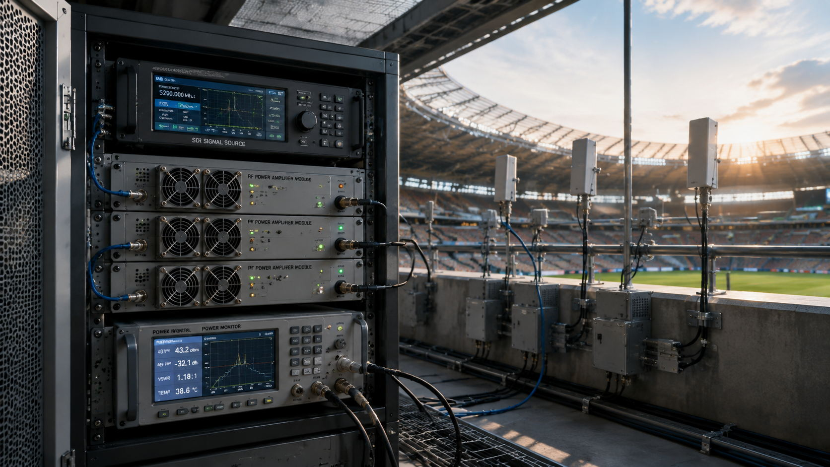
An SDR can drive an RF PA to target output during one bench test and still leave too little margin for real operation.
If the source is already close to its maximum stable output, extra path loss, a lower-gain frequency, or hot-state change may pull Pout below the requirement. Raising the SDR level may recover that weak point, but it can also push another operating point closer to compression.
The real question is not whether the SDR can drive the PA once.
It is whether the complete RF chain has a repeatable operating window between underdrive and the PA input boundary.
For RF Power Amplifier Modules, this decision should be based on Actual Pin, corrected Pout, measured Pout-vs-Pin behavior, source capability, PA input limits, frequency, waveform, and thermal state.
SDR-to-PA matching is not proven by a software gain setting, a maximum SDR output specification, or a typical PA gain value.
The PA responds to the actual RF power reaching its input reference plane.
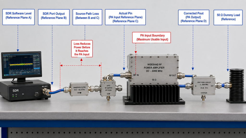
Keep these values separate:
Actual Pin may differ from the SDR-port output because of cable, filter, switch, connector, attenuation, and driver-stage losses.
The detailed method for checking Actual Pin after source-chain loss should remain separate from the drive-margin decision.
A valid operating point must prove two things:
The usable margin is controlled by whichever limit comes first:
The maximum stable Actual Pin available from the source chain or the maximum recommended PA Pin.
The SDR must also provide enough adjustment resolution to hold the selected operating point.
A wide output range is not useful when the target sits too close to the source maximum, the PA input boundary, or between two coarse SDR settings.
A first estimate of the required PA input is:
Required Pin = Target corrected Pout − measured large-signal gain near the target operating point
For example:
This is a planning calculation, not the final acceptance result.
Do not use typical datasheet gain or low-level small-signal gain without checking the real operating condition. Near target output, PA gain may change with Pin, frequency, waveform, temperature, load, and supply voltage.
The difference between small-signal and large-signal RF PA gain matters because a low-drive gain result may not predict the Pin required at the intended output.
The final Required Pin should therefore be confirmed from measured Pout-vs-Pin data.
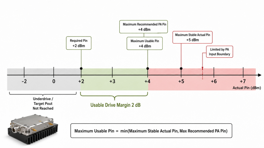
The source and PA create two limits:
The highest usable operating Pin is the lower of these two values:
Maximum usable Pin = min(Maximum stable Actual Pin, Maximum recommended PA Pin)
The usable drive margin is:
Usable drive margin = Maximum usable Pin − Required Pin
Consider this example:
The source can provide 3 dB above the required point, but the PA allows only 2 dB.
Therefore:
Maximum usable Pin = +4 dBm
Usable drive margin = 2 dB
The PA input boundary controls the decision.
This avoids counting all available SDR output as usable margin when the PA cannot accept it.
Required Pin and corrected Pout must use defined reference planes.
A clean comparison may use:
Do not subtract an SDR-port output value from an antenna-end output value unless every intermediate loss and correction is included.
Otherwise, the result may combine source-path loss, PA gain, output feeder loss, and antenna-path behavior.
A single gain number cannot show the complete operating window.
A Pout-vs-Pin sweep shows how corrected output changes as Actual Pin increases. It should identify:
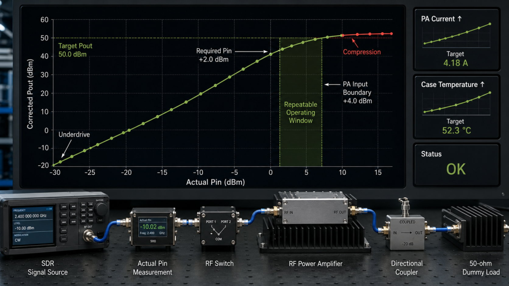
Underdrive occurs when the available Actual Pin is below the level needed to reach target Pout.
Possible causes include:
A system with no remaining source margin may pass one short bench test but fail after installation or thermal buildup.
As Actual Pin increases, the PA may show:
The planned operating point should remain below the project’s agreed upper boundary.
That boundary should not be based only on severe protection or obvious failure. It should preserve enough room for source variation, frequency changes, and thermal movement.
Enough source output does not always mean enough control.
Check:
If one SDR setting step changes Actual Pin by 1 dB while the usable drive margin is only 0.8 dB, the source cannot hold the operating point reliably.
Drive margin is not one fixed value for the entire project.
It should be checked under the conditions that can increase Required Pin or reduce the usable upper boundary.
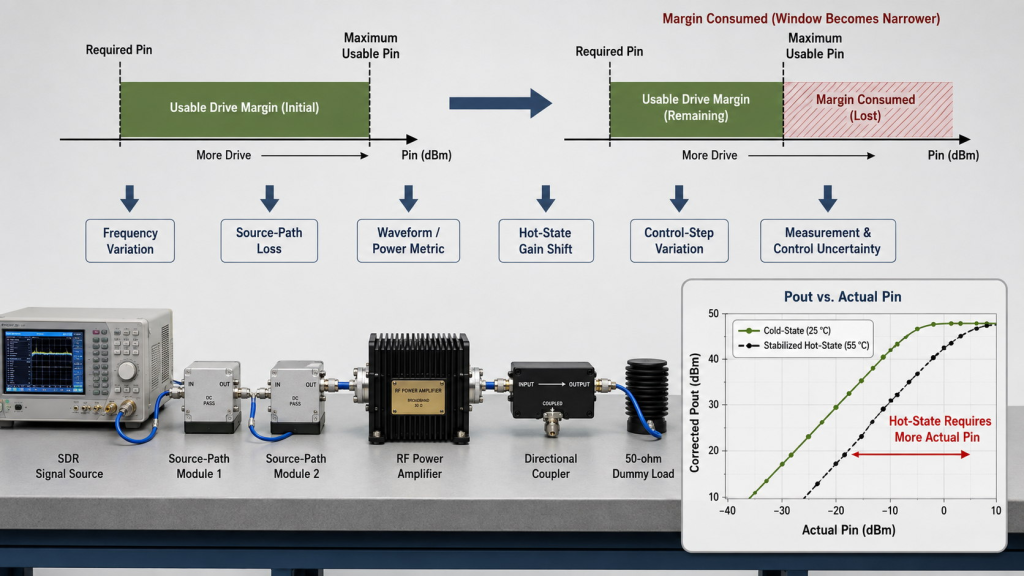
At each required frequency, verify:
Do not use average gain across a wide band.
If the system uses one common SDR setting, the required frequencies must share an overlapping usable window. If frequency-specific settings are available, each operating point still needs its own verified margin.
The RFQ should state whether Pin and Pout represent:
Do not mix different power definitions in one margin calculation.
For wider or higher-crest-factor signals, also define:
The source and PA must be compared under the same signal condition.
Usable PA gain may change as the amplifier warms.
If hot-state gain falls, Required Pin rises and consumes part of the remaining SDR headroom.
The test should define:
A nominal drive margin may be misleading when it is close to:
When these factors consume most of the calculated margin, the project should use a guard band or engineering-review zone instead of treating the complete nominal value as usable.
Once the required frequencies, Actual Pin range, target Pout, waveform, and thermal boundary are defined, the available SDR and PA routes can be compared against the same drive-window requirement.
The source route should provide enough measured output and adjustment control to reach Required Pin without operating continuously at its upper limit.
The PA route should reach the required corrected Pout while keeping the planned Actual Pin below the agreed input boundary at every critical frequency.
The specifications shown in this product area can narrow the available hardware routes. They do not prove the final SDR-to-PA match.
The selected combination should still be verified through Actual Pin, corrected Pout, and Pout-vs-Pin measurements under the project’s defined frequency, waveform, load, cooling, and thermal conditions.
Start with the SDR architecture because frequency coverage, real-time bandwidth, RF-output routing, control capability, and operating conditions determine whether the required Actual Pin can be generated and held.
CUSTOM IQ / CASCADING ROUTE
A stronger starting point when the system needs custom IQ loading, up to 200 MHz real-time bandwidth, RS422 AT-command control, and documented multi-unit cascading.
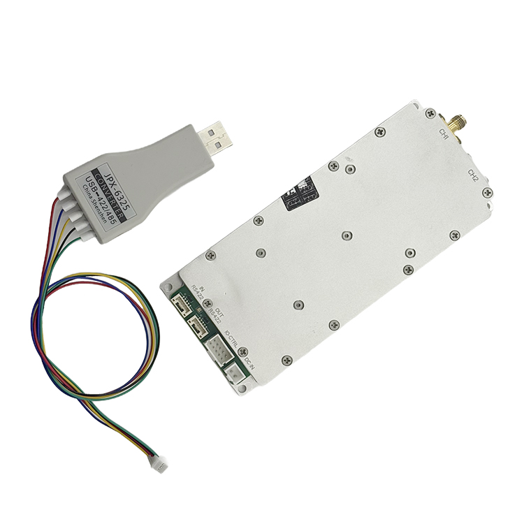
DUAL RF OUTPUT / WIDE TEMPERATURE ROUTE
A stronger starting point when two independent SMA outputs, up to 100 MHz per channel, a 9-32 V supply range, and wider operating temperature coverage are priorities.
| Selection Condition | HZS1006000-F1 | HZSDR1006000-A01 |
|---|---|---|
| Frequency Coverage | 100 MHz–6 GHz | 100 MHz–6 GHz |
| Real-Time Bandwidth | Up to 200 MHz | Up to 100 MHz per channel; 200 MHz combined |
| RF Output Architecture | Dual-PHY internal architecture with one documented external SMA output; confirm PHY-to-port routing. | Two independent SMA RF outputs |
| Custom IQ Support | USB upload of 16-bit complex IQ files; confirm the current .sc16 / .cs16 naming convention. |
Not documented in the current manual; confirm by RFQ. |
| Expansion | RS422 cascading of up to 10 units | Multi-module addressing and control supported; maximum quantity confirm by RFQ. |
| Control | RS422 AT-command control; customer application development supported | RS422 host control; custom API availability confirm by RFQ. |
| Supply | 28-32 V DC | 9-32 V DC |
| Operating Temperature | 0°C to 50°C | −40°C to +70°C |
Before RFQ: Confirm final firmware, physical RF-port routing, IQ-file convention, control/API availability, expansion limits, and the approved product revision.
After the source route is defined, review the PA series that covers every required frequency and output target. Final selection should still be based on measured Required Pin, Actual Pin, and Pout-vs-Pin behavior rather than nominal gain alone.
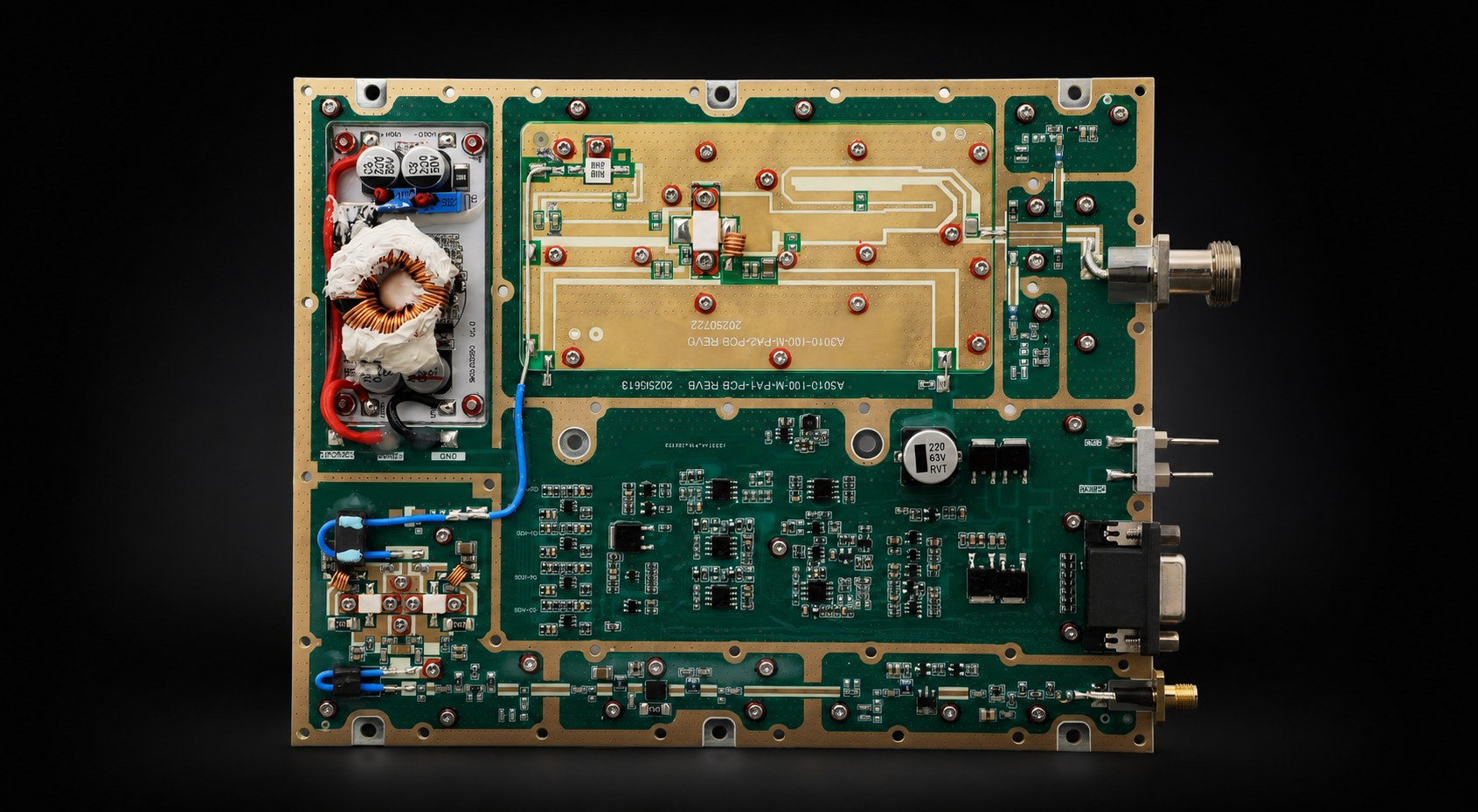
Wideband RF PA modules for multi-band integration across lower cellular, telemetry, and RF testing applications.
| Output Power | Module Type | Datasheet |
|---|---|---|
| 30W | Wideband RF PA module | Download 30W Datasheet |
| 50W | Wideband RF PA module | Download 50W Datasheet |
| 100W | Wideband RF PA module | Download 100W Datasheet |
| 150W | Wideband RF PA module | Download 150W Datasheet |
| 200W | Wideband RF PA module | Download 200W Datasheet |
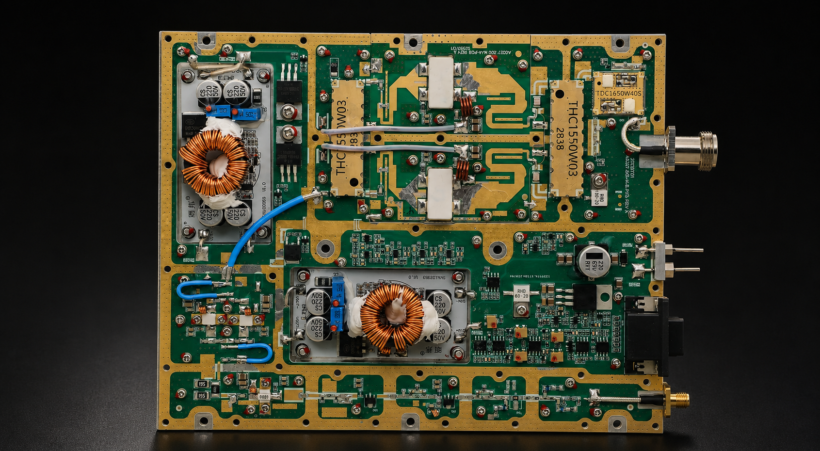
A core wideband PA range for RF power amplifier module buyers who need continuous 300-2700MHz coverage in one series.
| Output Power | Module Type | Datasheet |
|---|---|---|
| 30W | Wideband RF PA module | Download 30W Datasheet |
| 50W | Wideband RF PA module | Download 50W Datasheet |
| 100W | Wideband RF PA module | Download 100W Datasheet |
| 150W | Wideband RF PA module | Download 150W Datasheet |
| 200W | Wideband RF PA module | Download 200W Datasheet |
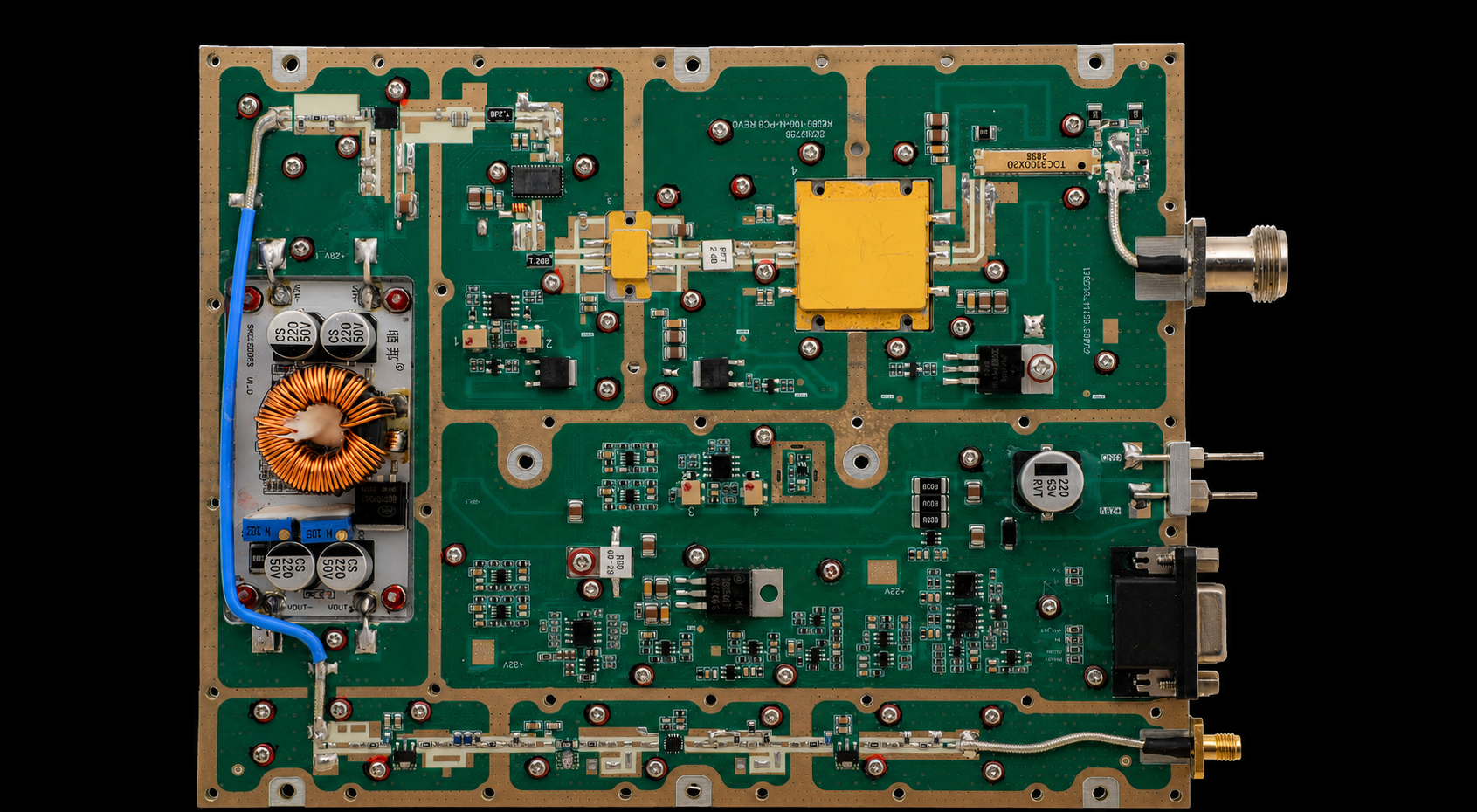
High-frequency RF PA modules for upper-band RF systems, band-specific projects, and custom frequency requirements within 2-6GHz.
Band-specific and custom RF PA module requirements can be reviewed from this series by project frequency, output power, thermal condition, and test-report needs.
| Output Power | Module Type | Datasheet |
|---|---|---|
| 30W | Wideband / band-specific RF PA module | Download 30W Datasheet |
| 50W | Wideband / band-specific RF PA module | Download 50W Datasheet |
| 100W | Wideband / band-specific RF PA module | Download 100W Datasheet |
| 150W | Wideband / band-specific RF PA module | Download 150W Datasheet |
| 200W | Wideband / band-specific RF PA module | Download 200W Datasheet |
The RFQ should connect the required operating point with the source and PA boundaries.
One maximum-output screenshot is not enough.
| Frequency | Signal Condition | Required Pin | Max Stable Actual Pin | Max Recommended PA Pin | Usable Margin | Control Step | Result |
|---|---|---|---|---|---|---|---|
| Point 1 | Defined | Record | Record | Record | Calculate | Record | Pass / Review / Fail |
| Point 2 | Defined | Record | Record | Record | Calculate | Record | Pass / Review / Fail |
| Point 3 | Defined | Record | Record | Record | Calculate | Record | Pass / Review / Fail |
Usable Margin = min(Max Stable Actual Pin, Max Recommended PA Pin) − Required Pin
The supporting test record should also include:
Before selecting the SDR and PA combination, define:
A stronger RFQ statement is:
Provide SDR-to-PA Pout-vs-Pin data at each required frequency using Actual Pin at the PA input reference plane and corrected Pout at the agreed output reference plane. Identify the signal condition, Required Pin, maximum stable Actual Pin, maximum recommended PA Pin, usable drive margin, control step, thermal state, load, and final acceptance result.
If none of the standard PA series preserves the required drive window across all target frequencies, use the completed drive-margin record to define a custom frequency, output-power, cooling, connector, and control configuration.
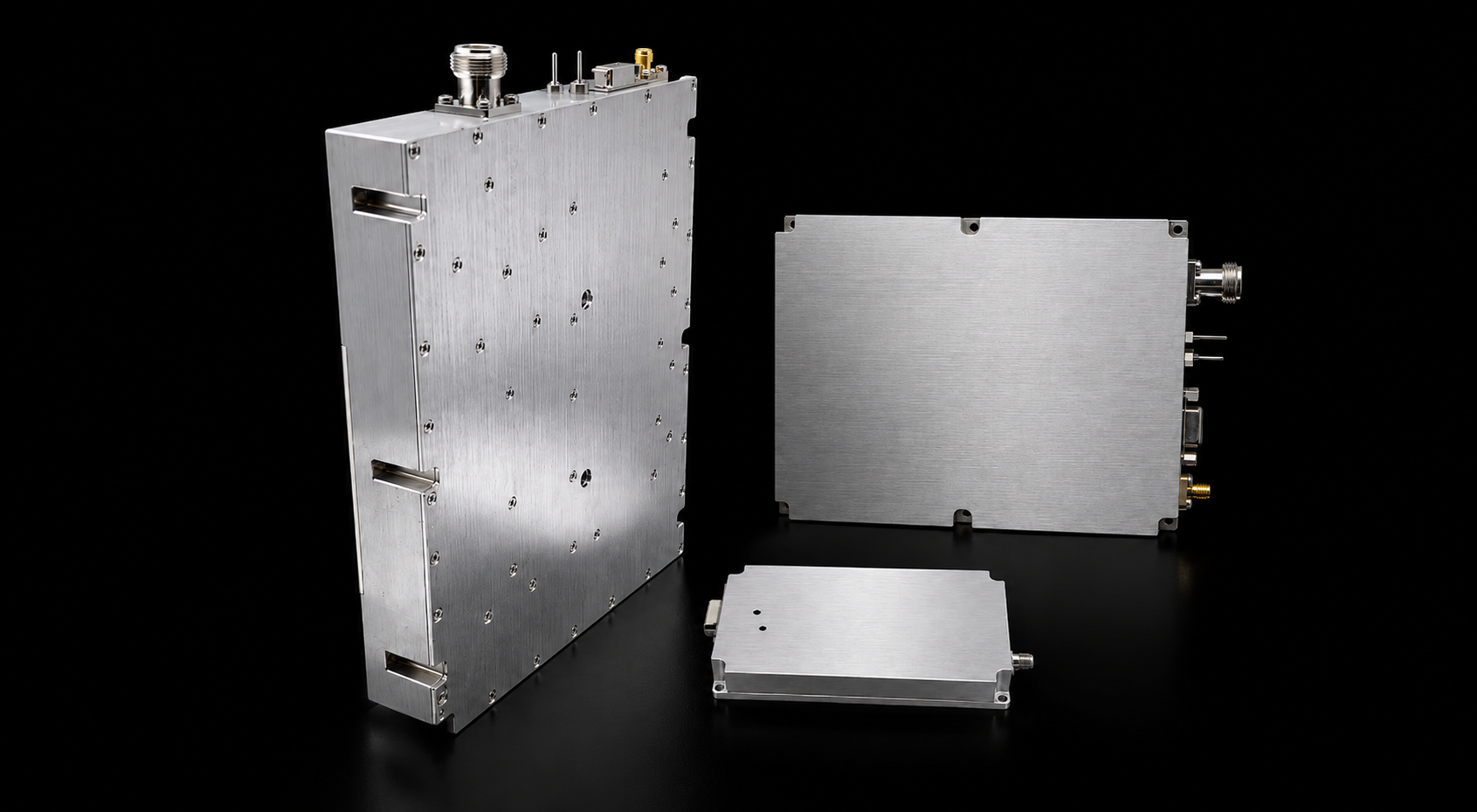
If standard RF PA modules do not match the required frequency, output power, voltage, cooling, connector, or control interface, RF SKYPOWER can review a custom RF PA module configuration before RFQ.
| Custom Item | Available Range / RFQ Detail |
|---|---|
| Frequency Range | Custom frequency coverage from 20MHz to 20GHz, based on target frequency points and band-edge requirements. |
| Output Power | Project-defined RF output from 10W to 1000W, depending on frequency, duty cycle, cooling, and system integration conditions. |
| Engineering Review | Confirm voltage, gain, input drive, connector, heatsink or forced-air cooling, VSWR protection, control interface, and test-report requirements before RFQ. |
SDR-to-PA matching is not proven because the source reaches target output once.
The usable margin is the difference between Required Pin and whichever upper limit comes first: the maximum stable Actual Pin available from the source chain or the maximum recommended PA Pin.
That margin should be verified with Pout-vs-Pin data at the required frequencies, waveform, and thermal state.
For broader RF PA module selection for C-UAS, SDR drive should be reviewed together with frequency coverage, output requirement, thermal design, load, control, and acceptance evidence.
Projects that still need to define source output, bandwidth, waveform, or control capability can review the SDR signal source module options before finalizing the interface.
RF SKYPOWER can support an early SDR-to-PA drive-margin review. Provide the required frequencies, signal condition, measured source output, expected source-path loss, target corrected Pout, PA input boundary, thermal condition, and required test evidence.