











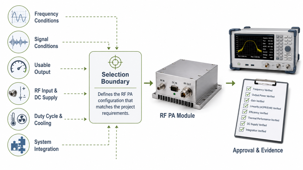
RF PA selection can fail even when frequency coverage and wattage appear to match. Before requesting a quotation, the project must define the signal type, usable RF output, measurement reference plane, available RF input, DC supply, duty cycle, cooling boundary, RF path, control requirements, and approval evidence.
A listed product family can provide the first selection path. It cannot confirm final suitability until the electrical, thermal, mechanical, RF, and test conditions are known.
RF SKYPOWER provides listed wideband families and custom RF Power Amplifier Modules for projects that need a defined frequency, output, interface, cooling, control, or evidence configuration. C-UAS projects with waveform, simultaneous-operation, antenna-path, and system-control requirements should also follow the dedicated C-UAS RF PA selection process.
1. What Must Be Defined Before RF PA Module Selection?
A useful RFQ begins with the operating boundary, not with a request for the highest available power.
Before comparing modules, define seven groups of information:
- Frequency conditions: required range, operating points, priority frequencies, band edges, and switching sequence
- Signal conditions: CW, pulsed, modulated, or multi-carrier operation, including instantaneous bandwidth where relevant
- Output conditions: required power type, minimum usable output, and measurement reference plane
- Input and supply conditions: available RF input, DC voltage at the PA terminals, and current capacity
- Operating conditions: duty cycle, maximum continuous duration, ambient temperature, and cooling method
- Integration conditions: RF connectors, downstream path, expected mismatch, control, alarm, and protection requirements
- Evidence conditions: prototype test scope, shipment evidence, S/N traceability, and any waveform-specific acceptance limits
Missing information should be marked as an open engineering question. It should not be silently converted into a supplier assumption.
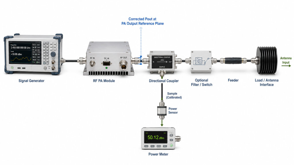
Define the output reference plane
A requirement of 100 W at the PA output connector is not the same as 100 W at the cabinet output, feeder end, or antenna input.
Filters, switches, couplers, adapters, connectors, and feeder cables can reduce the available downstream power. The RFQ must therefore state:
- the required output value;
- the type of output being specified;
- the point where the value must be measured.
Examples include:
- 50.0 dBm CW at the PA output connector;
- minimum average output at the cabinet RF port;
- minimum delivered power after a defined feeder;
- minimum power at the antenna input.
Values measured at different reference planes should not be compared as though they describe the same requirement.
2. How to Match the Required Frequencies to a Listed RF PA Family
Begin with the frequencies the project will actually use.
The widest listed range is not automatically the best choice. Wider coverage can affect gain flatness, available output margin, RF input requirement, efficiency, thermal behavior, filtering, and test scope.
RF SKYPOWER lists several wideband RF power amplifier module families as initial product-selection paths.
These families provide product guidance. They do not replace project-specific confirmation.
The RFQ should distinguish between:
- mandatory operating points;
- priority test points;
- full swept range;
- band-edge points;
- switching frequencies;
- future expansion frequencies.
A project that operates at several selected points inside a broad range may not require identical performance at every intermediate frequency. Another project may require full swept-frequency evidence.
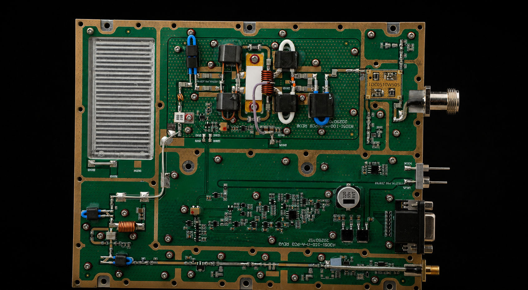
30-512MHz GaN RF Power Amplifier Modules
Low-frequency GaN RF PA modules for VHF/UHF communications, telemetry, RF testing, and project-defined low-band RF chains.
Best Fit: Projects that need wide VHF/UHF coverage from one PA family.
RFQ Focus: Confirm target points, required output, antenna-path loss, current draw, cooling, and band-edge evidence.
| Output Power | Datasheet |
|---|---|
| 30 W | Download 30 W Datasheet |
| 50 W | Download 50 W Datasheet |
| 100 W | Download 100 W Datasheet |
| 150 W | Download 150 W Datasheet |
| 200 W | Download 200 W Datasheet |
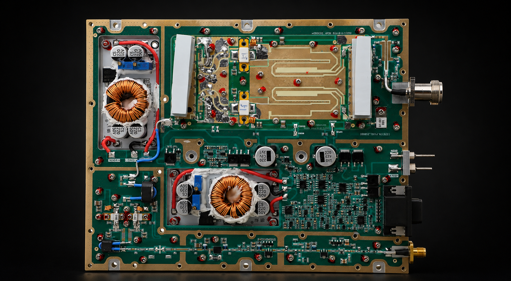
300-1200MHz GaN RF Power Amplifier Modules
Wideband GaN RF PA modules for communications, telemetry, SDR-driven systems, and subsystem integration across UHF and lower microwave bands.
Best Fit: Systems that need a continuous 300–1200 MHz route without extending into a broader upper band.
RFQ Focus: Confirm target-frequency output, input drive, gain flatness, duty cycle, DC margin, and thermal conditions.
| Output Power | Datasheet |
|---|---|
| 30 W | Download 30 W Datasheet |
| 50 W | Download 50 W Datasheet |
| 100 W | Download 100 W Datasheet |
| 150 W | Download 150 W Datasheet |
| 200 W | Download 200 W Datasheet |
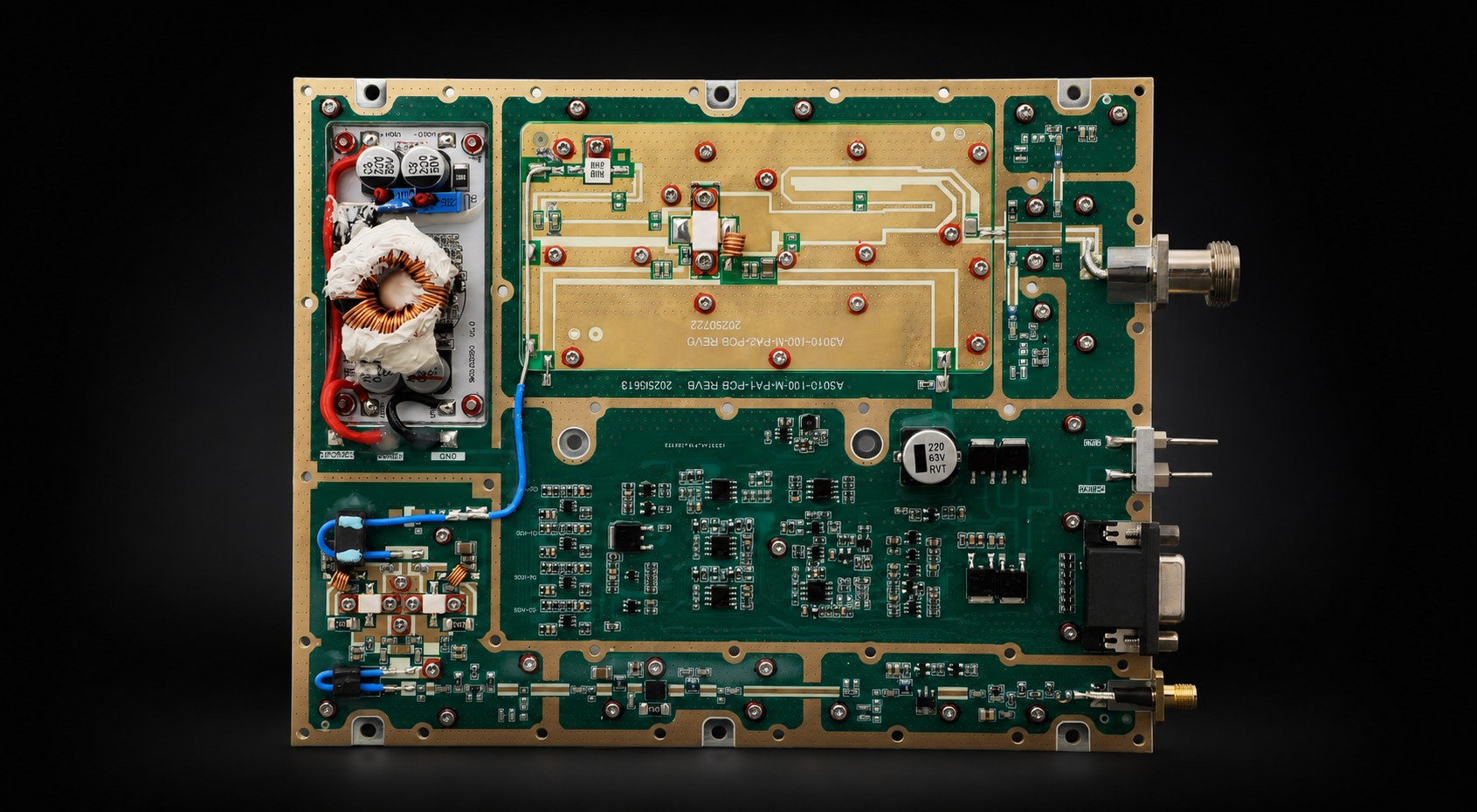
300-1700MHz GaN RF Power Amplifier Modules
Wideband GaN RF PA modules for multi-band communications, telemetry, SDR-driven systems, and RF testing across the 300–1700 MHz range.
Best Fit: Multi-band platforms that need broader mid-band coverage from a single PA family.
RFQ Focus: Confirm output and gain at priority points, switching behavior, thermal margin, control requirements, and swept evidence.
| Output Power | Datasheet |
|---|---|
| 30 W | Download 30 W Datasheet |
| 50 W | Download 50 W Datasheet |
| 100 W | Download 100 W Datasheet |
| 150 W | Download 150 W Datasheet |
| 200 W | Download 200 W Datasheet |
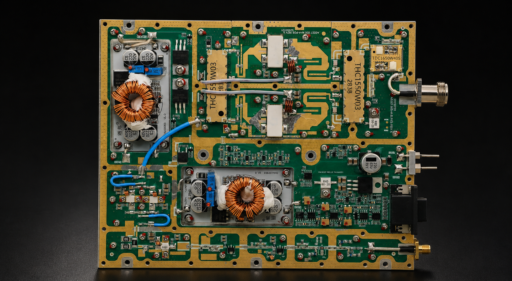
300-2700MHz GaN RF Power Amplifier Modules
Wideband GaN RF PA modules for projects that need continuous 300–2700 MHz coverage in one PA family.
Best Fit: Broad multi-band RF chains where one PA family can reduce the number of band-specific modules.
RFQ Focus: Confirm target-point output, gain flatness, input drive, efficiency, VSWR boundary, cooling, and test scope.
| Output Power | Datasheet |
|---|---|
| 30 W | Download 30 W Datasheet |
| 50 W | Download 50 W Datasheet |
| 100 W | Download 100 W Datasheet |
| 150 W | Download 150 W Datasheet |
| 200 W | Download 200 W Datasheet |
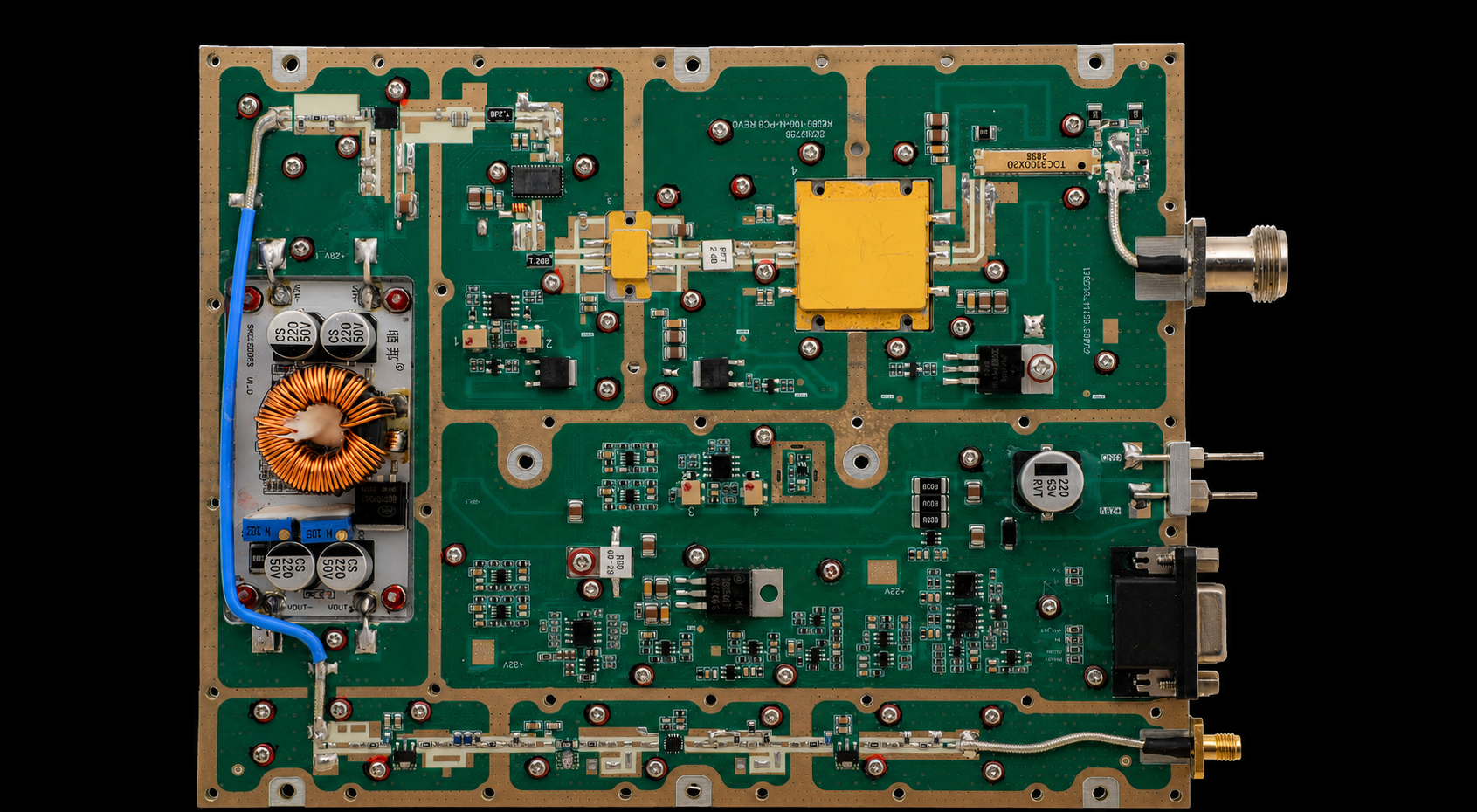
2000-6000MHz GaN RF Power Amplifier Modules
High-band GaN RF PA modules for 2–6 GHz systems and band-specific upper-frequency projects.
Best Fit: High-band RF chains that prioritize selected operating points within the 2–6 GHz range.
RFQ Focus: Confirm target-frequency output, connector and feeder loss, antenna match, thermal conditions, input drive, and required evidence.
| Output Power | Datasheet |
|---|---|
| 30 W | Download 30 W Datasheet |
| 50 W | Download 50 W Datasheet |
| 100 W | Download 100 W Datasheet |
| 150 W | Download 150 W Datasheet |
| 200 W | Download 200 W Datasheet |
Requirements outside the listed frequency, output, interface, cooling, control, or report conditions should enter custom engineering review before quotation.
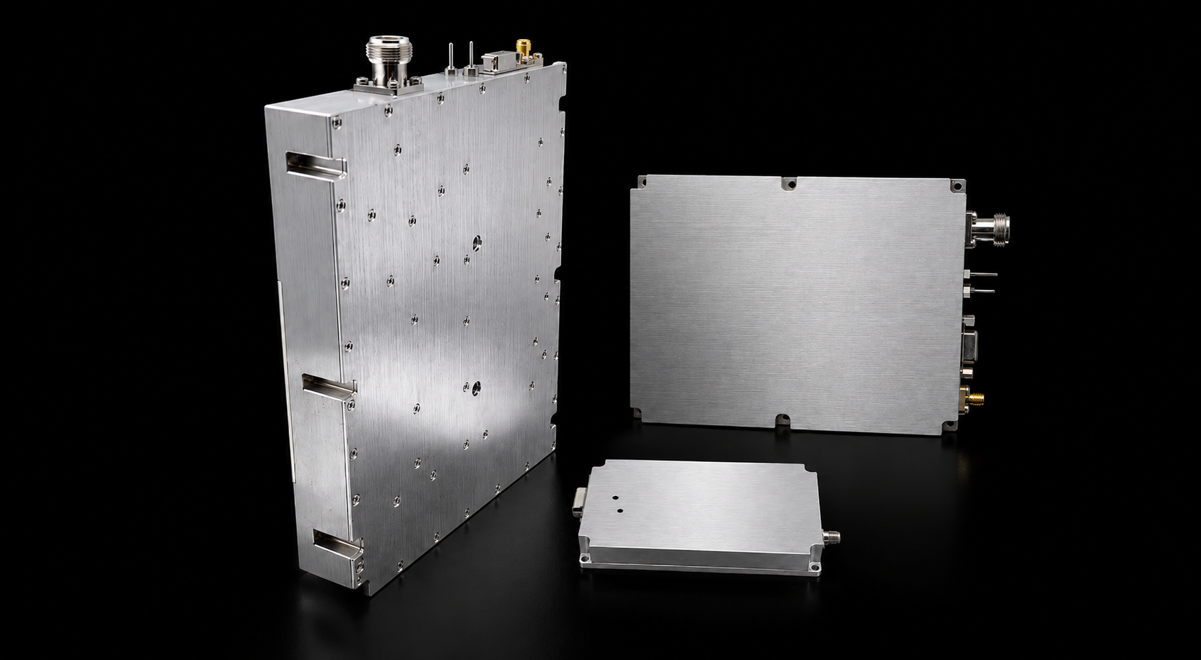
Custom RF PA Module Options
If no listed RF PA family matches the required frequency, output power, voltage, cooling, connector, control interface, or evidence scope, submit these conditions for custom engineering review.
| Custom Item | Available Range / RFQ Detail |
|---|---|
| Frequency Range | Custom frequency coverage from 20 MHz to 20 GHz, based on required operating points and band-edge conditions. |
| Output Power | Project-defined RF output from 10 W to 1000 W, subject to frequency, waveform, duty cycle, cooling, and integration conditions. |
| Engineering Review | Confirm RF input, gain, supply voltage, connector, cooling method, VSWR protection, control interface, mechanical limits, and required test evidence before quotation. |
3. How to Define the Signal and Usable RF Output
Rated wattage alone does not confirm usable output in the installed system.
Usable output depends on the signal, frequency, input drive, DC condition, duty cycle, cooling, RF load, downstream loss, and stated measurement reference plane.
For example, 50.0 dBm represents 100 W at the defined reference plane. It does not prove that 100 W reaches the antenna after filters, switches, connectors, or feeder loss.
Specify the output type
The RFQ should identify whether the required value means:
- CW output;
- average modulated output;
- composite multi-carrier output;
- peak-envelope power.
These values are not interchangeable.
For modulated or multi-carrier operation, provide the following where required:
- waveform or modulation type;
- instantaneous RF bandwidth;
- occupied bandwidth;
- number of carriers;
- carrier spacing;
- peak-to-average power ratio;
- required operating backoff;
- simultaneous-operation condition;
- acceptable gain compression;
- linearity or spectral limits.
Instantaneous bandwidth is the RF bandwidth that the PA must handle at the same time under one operating condition. Occupied bandwidth describes the spectrum used by a modulated signal and should be specified separately.
A module that reaches the target CW output may require additional backoff during high-PAPR or multi-carrier operation.
Confirm output at the required frequencies
A single center-frequency result does not prove usable output across the project range.
State whether the supplier must provide:
- output at selected operating points;
- swept-frequency output;
- band-edge output;
- gain flatness;
- hot-state output;
- output after a defined operating duration;
- output during frequency switching;
- output during simultaneous operation;
- output under a defined mismatch condition.
This prevents one strong result from hiding reduced margin at another project-critical frequency.
Define duty cycle and operating duration
Continuous-wave operation creates a different electrical and thermal condition from short bursts or low-duty operation.
State:
- continuous or intermittent operation;
- on-time and off-time;
- repetition pattern;
- maximum continuous duration;
- simultaneous channel condition;
- ambient or enclosure temperature;
- cooling airflow or heat-sink boundary.
Power class should be shortlisted only after these conditions are defined. A specific wattage does not automatically determine whether the module belongs in a portable, vehicle, or fixed-site platform.
4. What Integration Limits Must Be Confirmed?
An RF PA module operates inside a larger RF, DC, thermal, mechanical, and control system.
A suitable module can still produce poor installed results when the surrounding boundaries are unclear.
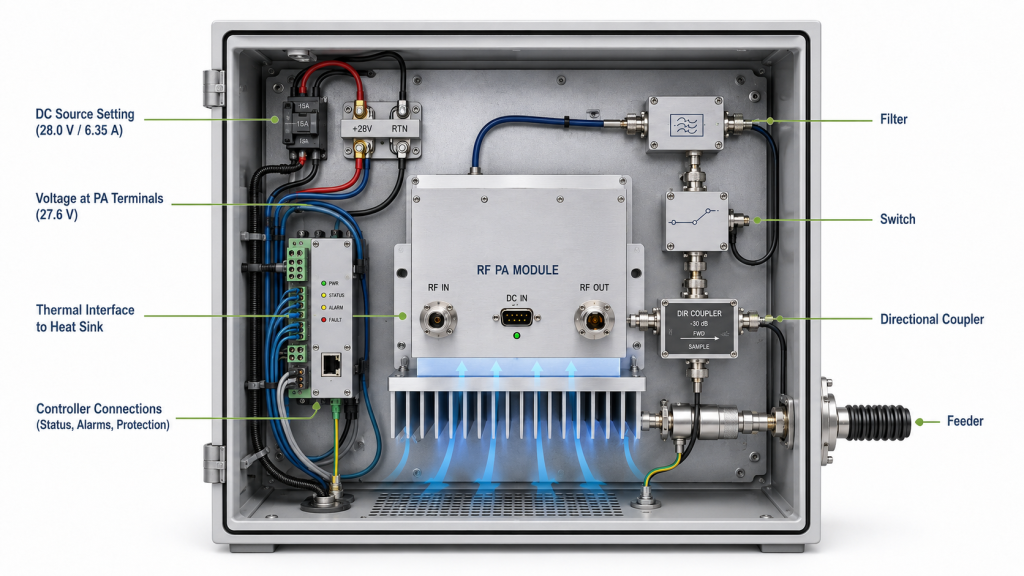
RF input and driver compatibility
State the available RF input at the PA input reference plane.
Do not rely only on the nominal output of an SDR, signal generator, or driver stage. Cable loss, splitters, switches, and connectors can reduce the input reaching the PA.
Confirm:
- minimum, nominal, and maximum RF input;
- input variation by frequency;
- input reference plane;
- required gain or output-control range;
- startup and switching sequence.
Additional driver gain should not be assumed unless the integrator confirms it.
DC supply under RF load
For projects using a 28 V PA platform, record both:
- the DC source setting;
- the voltage measured at the PA terminals while RF output is active.
A nominal 28.0 V source does not prove that the module receives 28.0 V under load.
Cable resistance, connectors, fuses, switching devices, and conductor size can create voltage drop. This may reduce output margin or trigger protection earlier than expected.
Define:
- nominal supply voltage;
- allowed voltage range;
- available current;
- cable length and conductor size;
- connector type;
- PA-terminal voltage under load;
- grounding arrangement;
- startup-current boundary.
Cooling and thermal interface
The quoted output must be connected to a defined cooling condition.
State whether the design assumes:
- external heat sink;
- forced-air cooling;
- conductive cooling;
- cold plate;
- cabinet airflow;
- customer-provided thermal interface;
- supplier-provided cooling assembly.
Also define:
- ambient or enclosure temperature;
- installation orientation;
- airflow direction;
- heat-sink or baseplate boundary;
- maximum case temperature;
- required operating duration.
A result obtained on a large laboratory heat sink does not prove the same output inside a restricted cabinet.
RF path responsibility
The quotation should state whether verification of downstream RF components belongs to the PA supplier, RF subsystem supplier, antenna supplier, or system integrator.
Possible downstream elements include:
- filters;
- switches;
- couplers;
- adapters;
- feeders;
- connectors;
- antennas.
The module specification alone should not be used to assign responsibility for feeder loss, antenna mismatch, or installed-path performance.
Where required, the project should separate:
- PA-port performance into a defined 50 Ω load;
- downstream RF assembly performance;
- feeder-end or antenna-input power;
- installed reflected power and VSWR behavior.
Control, alarm, and protection
State which functions the system controller must command or monitor.
Possible requirements include:
- RF output enable and disable;
- frequency or channel selection;
- output-level control;
- temperature status;
- current status;
- forward-power status;
- reflected-power status;
- VSWR alarm;
- over-temperature protection;
- over-voltage protection;
- current limiting;
- fault reset;
- startup timing;
- project-defined command protocol.
The quotation should distinguish between standard functions, optional functions, project-specific development, and external-controller responsibilities.
5. What Evidence Is Needed Before Module Approval?
A specification sheet provides an initial product path. It does not prove that the quoted module meets the project boundary.
Before comparing suppliers, confirm the RF power amplifier datasheet conditions behind rated, typical, minimum, and maximum values.
| Area | Weak evidence | Evidence needed for approval |
|---|---|---|
| Frequency coverage | One center-frequency screenshot | Results at required points or across the agreed swept range |
| RF output | Uncorrected power-meter reading | Corrected output at a stated reference plane |
| Output definition | One wattage value without signal conditions | CW, average, composite, or peak-envelope output under defined conditions |
| RF input | Nominal signal-source setting | Input measured or calculated at the PA input reference plane |
| Gain | One typical gain value | Gain at agreed frequencies and operating conditions |
| DC condition | Power-supply front-panel setting | PA-terminal voltage and current while RF output is active |
| Thermal condition | Room-temperature startup result | Output, current, and temperature after the agreed operating duration |
| RF load | Statement that a 50 Ω load was used | Load type, RF path, reflected power, and VSWR condition |
| Waveform-specific performance | No modulation, linearity, or spectrum evidence | Gain-compression, intermodulation, harmonic, spurious, or spectral results where required by the waveform and architecture |
| Protection | Statement that protection is included | Defined trigger condition, observed behavior, and recovery result |
| Unit identity | Representative sample report | Model, S/N, hardware version, report number, and test date |
| Batch release | Generic laboratory report | Agreed evidence linked to each delivered unit or approved sampling plan |
Define the measurement correction path
The output report should state the losses and corrections between the PA output reference plane and the measuring instrument.
These may include:
- cable loss;
- connector loss;
- coupler factor;
- attenuator value;
- adapter loss;
- sensor correction;
- frequency-dependent correction.
The final reported output should identify the total correction and measurement reference plane.
A power-meter display alone may not represent the PA output when the sampled signal passes through a coupler, cable, and attenuator before reaching the sensor.
Require hot-state evidence when needed
A cold result can confirm startup. It cannot confirm sustained output.
For continuous or long-duration projects, request data after the module reaches the agreed thermal condition.
The record may include:
- frequency;
- signal type;
- RF input;
- corrected RF output;
- gain;
- PA-terminal voltage;
- current;
- case or baseplate temperature;
- forward power;
- reflected power;
- VSWR;
- cooling condition;
- operating duration;
- protection status.
Separate design approval from shipment acceptance
Engineering approval confirms that the proposed module configuration can meet the project requirement.
Shipment acceptance confirms that the delivered units match the approved configuration and report scope.
For final release, use a separate C-UAS RF PA acceptance checklist that connects each delivered model and S/N with the required evidence.
A representative sample report should not be presented as evidence for every delivered unit unless the agreed acceptance plan allows it.
6. What Should Be Included in the RF PA Module RFQ?
A complete RFQ allows technical conflicts to be identified before quotation.
| RFQ item | What to specify | Why it matters |
|---|---|---|
| Frequency requirement | Full range, operating points, priority points, and switching sequence | Defines the product family and test scope |
| Signal type | CW, pulsed, modulated, or multi-carrier | Changes output, thermal, and evidence requirements |
| Instantaneous bandwidth | Required simultaneous RF bandwidth at each operating condition; provide occupied bandwidth separately for modulated signals | Affects matching, linearity, gain flatness, and architecture review |
| Operating mode | Sequential, switched, or simultaneous operation | Affects DC, thermal, and control requirements |
| RF output | CW, average, composite, or peak-envelope target | Prevents different power definitions from being compared |
| Output reference plane | PA connector, cabinet port, feeder end, or antenna input | Keeps measured values comparable |
| RF input | Minimum, nominal, and maximum input at the PA input | Confirms gain and driver compatibility |
| PAPR and backoff | Required values for modulated or multi-carrier operation | Defines usable linear output |
| DC supply | Nominal voltage, allowed range, terminal voltage, and current capacity | Confirms electrical margin under RF load |
| Duty cycle | Continuous, pulsed, intermittent, and maximum on-time | Defines thermal and supply stress |
| Cooling | Heat sink, airflow, cold plate, enclosure, and ambient condition | Connects output to a real thermal boundary |
| RF path | Connectors, filters, switches, couplers, feeders, and antennas | Defines downstream loss and responsibility |
| Load condition | Expected VSWR, reflected-power boundary, and mismatch duration | Defines protection and validation requirements |
| Control interface | Enable, level control, frequency control, alarm, status, and protocol | Prevents interface redesign |
| Mechanical limits | Dimensions, weight, mounting, and connector orientation | Confirms physical integration |
| Environmental limits | Operating temperature, storage temperature, vibration, and installation condition | Defines qualification scope |
| Waveform-specific limits | Gain compression, intermodulation, harmonic, spurious, or spectral limits where required | Defines signal-specific acceptance evidence |
| Test evidence | Frequency, output, gain, DC, thermal, protection, and S/N requirements | Defines what must be proven before approval |
| Quantity | Prototype, pilot, and production quantity | Affects configuration and delivery planning |
| Open questions | Conditions that still require engineering review | Prevents assumptions from entering the quotation |
The RFQ should separate confirmed conditions from open questions.
For example:
- Confirmed: 300–2700 MHz operating range
- Confirmed: defined priority frequencies
- Confirmed: 28 V DC platform
- Confirmed: continuous operation
- Open: final cabinet airflow
- Open: antenna-path VSWR boundary
- Open: required waveform-specific evidence
- Open: unit-level shipment report scope
This allows the supplier to assess the listed product family while clearly identifying the conditions that still require engineering review.
Conclusion
Use the listed frequency families to identify the initial product path, then confirm the signal, usable output, reference plane, electrical supply, thermal boundary, RF path, control requirements, and approval evidence.
A listed module may be suitable when these conditions match the available configuration. Other requirements should enter engineering review before the quotation is finalized.
Send the completed RFQ boundary through the RF SKYPOWER contact page for review. RF SKYPOWER can then confirm whether the request fits a listed RF PA module family or requires a custom frequency, power, interface, cooling, control, or evidence configuration.