











RF PA equalization can appear successful while the system is already hiding a failed path. Several modules may show nearly identical output on the same screen, yet one path may be underdriven, another may be close to compression, and a third may lose power only after heat builds or the measurement moves beyond the PA output connector.
The dangerous part is that drive, gain, and attenuation settings can make these paths look balanced. Once the test moves to the correct reference plane, stabilized hot state, installed RF path, or simultaneous operating condition, the apparent match may disappear.
For standard or custom RF Power Amplifier Modules, the approval question is therefore not whether every display can be forced toward the same number. It is whether each path remains inside its approved output window without hiding underdrive, compression, voltage drop, mismatch, thermal rollback, protection activity, or an incorrect measurement correction.
A valid equalization process must expose that false balance, calculate each path’s actual error, identify which differences may be adjusted, and prove that the final result remains valid under the full operating state.
1. Define the Equalization Target and Calculate the Error
“Make all modules equal” is not a complete engineering requirement.
Before testing, define:
- Required operating frequencies
- Signal condition: CW, pulsed, or modulated
- Carrier configuration: single-carrier or multi-carrier
- Output type: CW, average, composite, or peak-envelope power
- Target output for each path
- Common measurement reference plane
- Approved output window
- Maximum allowed path-to-path difference
- Measurement uncertainty and decision rule
- Load, duty-cycle, thermal, and simultaneous-operation conditions
Use one reference plane for each comparison
Possible reference planes include:
- PA output connector
- Cabinet RF output
- Feeder end
- Antenna input
Results from different reference planes cannot be compared directly.
For example, 50.0 dBm represents 100 W at the stated reference plane. It does not prove that the same power reaches the cabinet output or antenna input after filters, switches, couplers, connectors, and feeder loss.
If the project requires several reference planes, separate the results into groups:
- PA-port baseline
- Cabinet-output result
- Feeder-end result
- Antenna-input result
Do not compare a PA-port value from one path with an antenna-input value from another path and call the system equalized.
The same boundary must be used when comparing rated and usable RF output. Rated power identifies a product class. Usable output depends on the signal, frequency, input drive, DC condition, cooling, load, and measurement location.
Calculate the path difference correctly
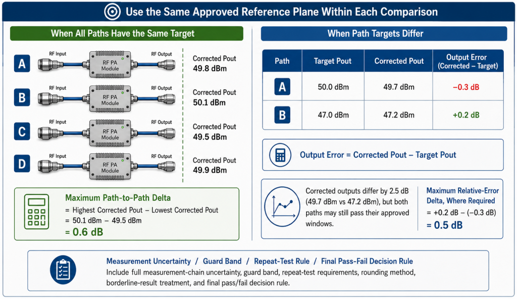
When all paths have the same target output, calculate the maximum path-to-path difference from corrected output values:
Maximum path-to-path delta = Highest corrected Pout − Lowest corrected Pout
Example:
| Path | Corrected Pout |
|---|---|
| A | 49.8 dBm |
| B | 50.1 dBm |
| C | 49.5 dBm |
| D | 49.9 dBm |
The maximum path-to-path delta is:
50.1 dBm − 49.5 dBm = 0.6 dB
That result must then be compared with the approved limit.
Compare error, not raw output, when targets differ
Some systems intentionally use different output targets for different paths.
In that case, calculate each path’s error relative to its own target:
Output error = Corrected Pout − Target Pout
Example:
| Path | Target Pout | Corrected Pout | Output error |
|---|---|---|---|
| A | 50.0 dBm | 49.7 dBm | −0.3 dB |
| B | 47.0 dBm | 47.2 dBm | +0.2 dB |
The raw outputs differ by 2.5 dB, but both paths may still pass their approved windows.
For paths with different targets, equalization should compare:
- Each path against its own minimum and maximum limit
- Each path’s error relative to its target
- The maximum difference between those relative errors, where required
Equalization does not always mean identical output.
Include measurement uncertainty in the decision
The acceptance method must account for the combined uncertainty of the measurement chain.
Possible contributors include:
- Power sensor accuracy
- Directional coupler factor
- Cable-loss correction
- Attenuator tolerance
- Connector repeatability
- Adapter loss
- Frequency-dependent correction
- Instrument calibration
- Reconnection repeatability
- Reported-value rounding
If the approved output window is close to the uncertainty of the complete measurement chain, the RFQ should define:
- Guard band
- Treatment of borderline results
- Repeat-test requirement
- Number of repeated measurements
- Rounding method
- Final pass/fail decision rule
A reported difference is not meaningful unless the test system can resolve it with adequate confidence.
2. Establish an Independent Baseline Before System-Level Equalization
Equalization should use two validation stages.
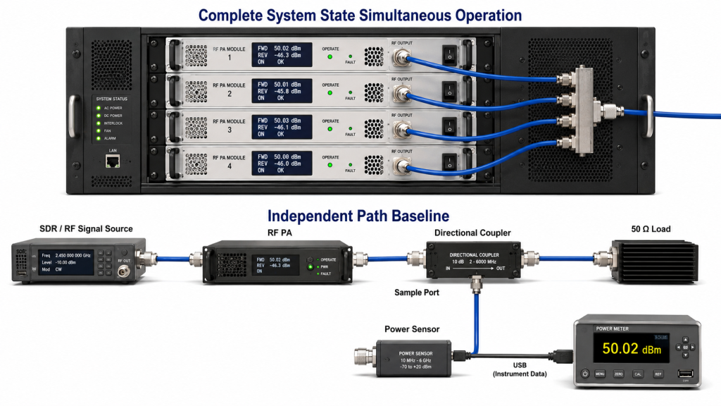
Stage 1: Independent Path Baseline
Test each PA path separately under a defined load.
This stage identifies differences caused by:
- RF input path
- PA gain
- PA-terminal voltage
- Current capacity
- Single-path thermal behavior
- Control state
- Protection state
- Module-level load behavior
Where practical, begin with a defined 50 Ω load. This separates PA behavior from installed feeder and antenna effects.
Projects that need to compare module and installed-path behavior can use dummy-load and real-antenna checks as separate validation stages.
Stage 2: Complete System State
After each independent path is understood, test the complete system in its required operating mode.
This stage identifies differences caused by:
- Shared DC supply droop
- SDR resource sharing
- Simultaneous channel operation
- Control timing
- Cabinet airflow
- Thermal interaction
- RF coupling
- Shared switching or filtering
- Simultaneous protection behavior
A path may pass alone but fall outside its window when several channels operate together.
Comparable Test Conditions for Every PA Path
| Record item | What must be captured |
|---|---|
| Path identity | Path ID, module model, S/N, and relevant configuration version |
| RF condition | Frequency, waveform, carrier configuration, and operating mode |
| Source condition | Source output and loss before the PA |
| Measured Pin | RF input at the PA input reference plane |
| Corrected Pout | Output corrected to the approved reference plane |
| DC condition | PA-terminal voltage and current while RF output is active |
| Thermal condition | Agreed case, baseplate, or heat-sink temperature and operating duration |
| Load condition | Defined 50 Ω load or installed RF path |
| Reflected condition | Forward power, reflected power, and VSWR where required |
| Control condition | Gain, attenuation, channel, enable, and alarm settings |
| Protection condition | Normal, limiting, rollback, alarm, or trip state |
Using the same signal-source front-panel setting is not enough.
Input cables, splitters, switches, attenuators, and connectors may create different losses before the signal reaches each PA. Equalization must therefore use measured Pin at the PA input reference plane rather than source output alone.
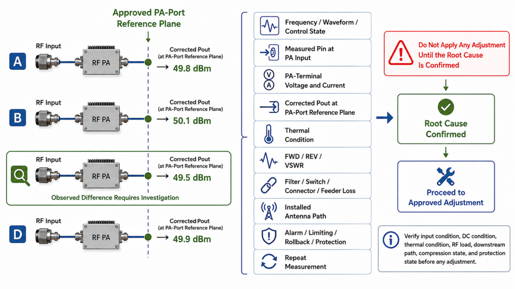
3. Identify the Cause Before Applying an Adjustment
Equalization is allowed only after the cause of the difference is understood.
A control setting can make two output readings look similar while leaving the real defect unresolved.
Use this investigation order:
- Confirm frequency, waveform, carrier configuration, and control state.
- Measure Pin at the PA input reference plane.
- Confirm PA-terminal voltage and current.
- Compare corrected PA-port output.
- Check the agreed temperature point.
- Check forward power, reflected power, and VSWR.
- Review feeder, filter, switch, connector, and adapter loss.
- Check the installed antenna path where required.
- Review alarms, limiting, rollback, and protection status.
- Repeat the measurement before approving a correction.
When Adjustment Is Allowed—and When It Is Not
| Observed condition | Is equalization adjustment allowed? | Required action |
|---|---|---|
| Pout is high while Pin, DC, temperature, load, and protection are normal | Yes | Reduce validated drive, apply approved gain control, or add calibrated attenuation |
| Pout is low because measured Pin is below the planned value | Conditionally | Correct the input path or increase drive only within verified drive margin |
| Pout is low while the PA is already near compression | No | Do not increase drive; review the PA operating point or module selection |
| PA-terminal voltage is below the approved boundary | No | Correct the DC cable, connector, supply, or shared-current limitation |
| Thermal rollback or current limiting is active | No | Correct cooling, airflow, thermal contact, or operating duty |
| Reflected power or VSWR is abnormal | No | Correct the load, connector, feeder, or antenna mismatch |
| The correction path is incomplete or unverified | No | Correct the measurement chain before judging the PA |
| PA-port output passes but cabinet or antenna-side output is low | Not through PA adjustment | Correct downstream filter, switch, connector, feeder, or antenna-path loss |
| One path does not meet its minimum output requirement | No | Repair, redesign, or replace the path before equalization |
| Several paths fall during simultaneous operation | Not until the shared cause is known | Check shared DC, thermal, SDR, control, switching, or coupling conditions |
Verify drive margin before increasing Pin
A low-output path may be underdriven, but it may also be affected by:
- Reduced PA gain
- Voltage drop
- Thermal rollback
- Compression
- Load mismatch
- Reflected-power limiting
- Incorrect correction data
- Control or protection state
Use measured Pout-versus-Pin data to identify:
- Linear or small-signal region
- Expected large-signal gain
- Target operating point
- Compression onset
- Maximum allowed Pin
- Available adjustment margin
The SDR drive margin must be verified at the PA input reference plane. Source output alone does not prove that enough drive reaches every module.
Understand the limit of attenuation
Attenuation can reduce a path that is above the approved window.
It cannot repair a path that is below the required minimum.
Do not lower all paths to the output of a defective module merely to produce similar numbers. Equalization must preserve the required minimum output and operating margin of every approved path.
4. Apply the Correction and Re-Verify the Full Operating State
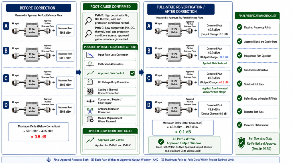
After the root cause is confirmed, apply only the correction that matches the observed problem.
Possible approved actions include:
- Correcting input-path loss
- Aligning SDR or signal-source output
- Adding calibrated attenuation to a high path
- Applying an approved gain-control value
- Correcting PA-terminal voltage drop
- Improving cooling or thermal contact
- Repairing a connector or feeder problem
- Correcting filter or switch insertion loss
- Resolving antenna mismatch
- Replacing a module that cannot meet the approved window
Every change must be followed by complete re-verification.
Re-run the required operating conditions
At minimum, repeat the applicable measurement set under:
- Required frequency points
- Approved signal and carrier configuration
- Independent path operation
- Required simultaneous operating state
- Stabilized hot-state condition
- Defined load or installed RF path
- Repeated test runs
- Spare or replacement path condition where required
An adjustment that corrects one frequency may create a new error at another frequency.
A setting that passes during independent operation may fail when several paths operate together.
A cold-state correction may also become invalid after temperature and current stabilize.
Apply the final pass criteria
The final result should pass only when:
- Every path is inside its own approved output window
- The maximum path-to-path delta or relative-error delta meets the defined limit
- No path is underdriven beyond the approved boundary
- No path is operating in an unapproved compression region
- PA-terminal voltage and current remain within limits
- Thermal, load, alarm, and protection conditions are acceptable
- The result remains valid in the required full operating state
- The acceptance decision follows the agreed uncertainty rule
A single corrected screenshot does not prove equalization.
5. Record Before-and-After Evidence
The final report should not repeat every raw test field without showing what changed.
It should prove:
- Original path imbalance
- Original corrected output and relative error
- Confirmed root cause
- Adjustment or repair applied
- Final drive, gain, or attenuation setting
- Before-and-after corrected output
- Final path-to-path or relative-error delta
- Frequencies and operating states re-verified
- Hot-state and simultaneous-operation result where required
- Measurement uncertainty and decision rule
- Model and S/N linkage
- Final pass/fail conclusion
The report should make it possible to answer four questions:
- What was outside the approved window?
- Why was it outside the window?
- What correction was applied?
- What evidence proves the complete system now passes?
For systems with intentionally different channel targets, equalization should not be confused with multi-channel RF power consistency. Equalization corrects comparable path errors against approved targets. Consistency analysis may compare channels with different frequencies, power levels, losses, and system roles.
RFQ: What Must Define Multi-Module Output Equalization?
The RFQ should define the equalization and acceptance method before module settings, attenuators, RF paths, and reports are approved.
RFQ Fields for Multi-Module Output Equalization
| RFQ field | What to specify |
|---|---|
| Path scope | Number of active, spare, sequential, and simultaneous paths |
| Frequency plan | Required frequencies, priority points, and switching sequence |
| Signal condition | CW, pulsed, or modulated operation |
| Carrier configuration | Single-carrier or multi-carrier, including simultaneous operation |
| Output target | Target, minimum, and maximum output for each path |
| Reference plane | PA port, cabinet port, feeder end, or antenna input |
| Equalization limit | Maximum path-to-path delta or relative-error delta |
| Uncertainty rule | Measurement uncertainty, guard band, repeat-test rule, rounding, and borderline-result treatment |
| RF input boundary | Source setting, source-path correction, measured Pin, maximum Pin, and compression boundary |
| DC boundary | Nominal voltage, PA-terminal voltage, current capacity, and shared-supply condition |
| Operating condition | Duty cycle, maximum duration, ambient condition, and stabilized thermal state |
| Cooling boundary | Heat sink, airflow, cold plate, enclosure, and temperature measurement point |
| RF path and load | Filters, switches, couplers, feeders, connectors, antennas, VSWR, and reflected-power limit |
| Control and protection | Gain, attenuation, enable, alarm, limiting, rollback, and reset behavior |
| Approved adjustment method | SDR level, calibrated attenuation, PA control, repair, or module replacement |
| Evidence scope | Before-and-after data, root cause, adjustment record, S/N linkage, repeated runs, and pass/fail report |
| Open questions | Conditions that still require engineering review |
A strong RFQ should separate confirmed requirements from open engineering questions.
For example:
- Confirmed: four PA paths
- Confirmed: common cabinet-output reference plane
- Confirmed: individual target output for each path
- Confirmed: maximum relative-error delta
- Confirmed: 28 V platform
- Open: final feeder loss
- Open: installed-path VSWR
- Open: simultaneous hot-state duration
- Open: whether spare paths require unit-level equalization evidence
This makes it clear what may be adjusted, what must be repaired, and what evidence is required before approval.
Conclusion
RF PA output equalization requires more than matching displayed power values.
Define the target and reference plane, calculate each path’s error, establish an independent baseline, identify the root cause, and apply only an approved correction. Then repeat the test under the required hot-state, load, and simultaneous operating conditions.
RF SKYPOWER can review the proposed equalization method before the RFQ and acceptance boundary are locked. Submit the completed path-level conditions through the RF SKYPOWER contact page to confirm which differences may be corrected through validated drive or attenuation settings and which require module, DC, thermal, load, control, or RF-path correction.