










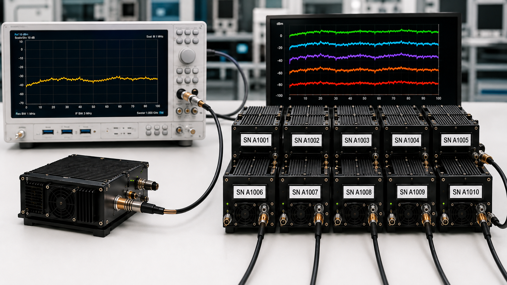
A clean engineering-sample gain trace can create early confidence in RF PA batch gain consistency long before production delivery begins. The difficulty appears later, when multiple delivered modules must share the same drive settings, acceptance limits, spare-unit strategy, and replacement rules.
In a multi-module C-UAS project, the risk is not that every small gain difference causes a failure. It is that an early sample may leave unit-to-unit spread, hot-state behavior, and replacement compatibility untested until commissioning or replenishment.
Before production approval, the buyer therefore needs to decide: what evidence actually shows that the delivered RF PA batch—not only the engineering sample—meets the required batch gain consistency boundary?
1. What One Engineering Sample Cannot Prove About a Batch
An engineering sample is useful. It can help confirm the basic design direction, frequency coverage, gain level, interface, mechanical fit, and early integration behavior.
But the sample represents only itself.
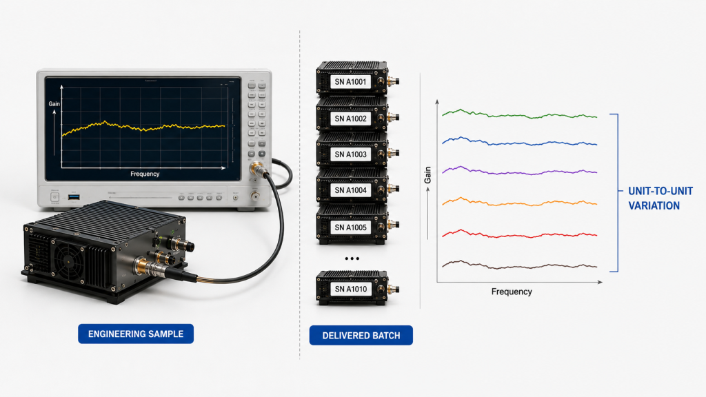
It may come from an early production run, a manually adjusted unit, or a module tested under carefully controlled conditions. Whether the later delivery contains a few modules or a much larger production batch, one engineering-sample trace does not reveal the unit-to-unit distribution of the delivered units.
This does not imply that the sample was intentionally selected to look better. The limitation is more fundamental: one trace contains no information about batch variation.
A sample gain curve cannot show:
- How widely gain varies across the delivered batch
- Whether the spread changes at different frequencies
- Whether some units shift higher or lower after heating
- Whether a spare module remains inside the original acceptance boundary
- Whether a later production batch remains compatible with the first delivery
Batch approval therefore needs evidence from the delivered population or from an agreed sampling plan. That evidence should identify the test frequency, input drive, thermal state, measurement boundary, acceptance limit, tested quantity, and module identification.
Where shipment acceptance requires broader traceability, serial-number-linked acceptance records can connect the tested result to the unit being delivered.
RF PA module selection should therefore consider not only whether one engineering sample meets the target, but also whether the required performance and evidence can be repeated across production delivery.
2. Why Unit-to-Unit Gain Spread Matters in Multi-Module C-UAS
In a multi-module system, unit-to-unit gain variation can turn one shared input setting into different RF output levels.
Gain describes how much the amplifier increases the input signal. When two modules are compared at the same frequency, input drive, Vdc, load, thermal state, and measurement plane, different measured gain means the modules do not respond identically at that test point.
This matters when one controller applies the same input setting to multiple RF paths.
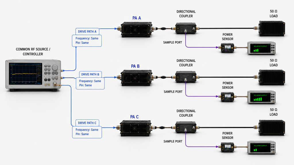
Excessive variation can lead to:
- Channel-to-channel imbalance
- Additional calibration during commissioning
- Different control values for nominally identical modules
- Replacement modules that disturb an existing calibration
- Unequal margin before gain compression
- Different behavior between the original delivery and later replenishment
The effect should not be exaggerated. A small gain difference does not automatically cause a system failure, and gain alone does not determine field coverage.
The engineering issue is that uncontrolled batch variation changes the RF power budget and makes repeated system behavior harder to predict.
When the same control value produces different path outputs, multi-module RF PA output equalization should first identify whether the difference comes from the PA, the RF path, the measurement boundary, or another system condition before drive or attenuation is adjusted.
Batch gain consistency must also remain separate from output-power consistency.
Two modules can look similar during a fixed-input gain comparison and still behave differently near the intended operating power because compression, current draw, temperature, protection margin, or maximum usable output can introduce additional differences.
If the application depends on rated or near-maximum RF output, a full-power RF PA test should evaluate that operating condition separately.
3. What Separates Gain Flatness from Batch Consistency
Gain flatness and batch gain consistency answer different acceptance questions.
Gain flatness measures how gain changes across frequency within one module.
Batch gain consistency measures how closely multiple modules match one another under the same test condition.
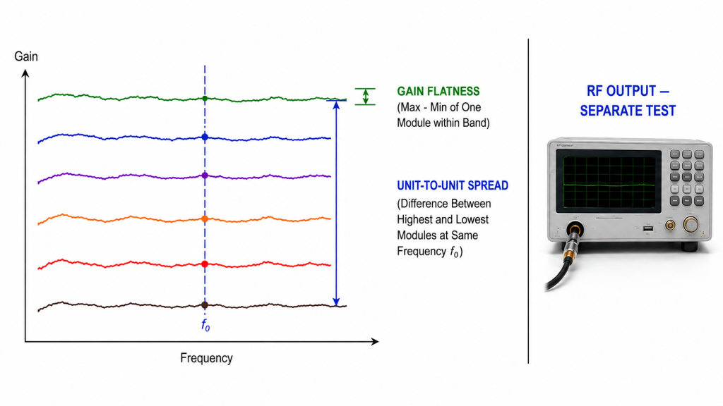
A module can have good gain flatness while its complete gain trace sits above or below the rest of the batch. Several units may therefore have similarly shaped curves without having the same absolute gain.
The reverse can also occur. Several modules may show similar gain at one center frequency while their individual gain-flatness behavior differs across the required band.
The buyer should therefore keep three questions separate:
- Gain flatness: Is one module reasonably even across the required frequency range?
- Batch gain consistency: Are different modules reasonably close under the same defined conditions?
- Output-power consistency: Do the modules deliver comparable usable output at the intended operating state?
The third question cannot be answered from gain data alone. Output verification may also depend on input drive, gain compression, thermal state, supply behavior, load condition, and the target operating power.
The RFQ should therefore identify which acceptance limit applies to within-unit flatness, which applies to unit-to-unit gain spread, and which—if required—applies to full-power output.
When unit-to-unit variation needs a formal pass/fail boundary, the separate RF PA gain tolerance requirement should define that measurable window before batch data are reviewed.
4. How to Compare Gain Across an RF PA Batch
Batch gain data are useful only when the tested units are compared under the same measurement boundary.
For a fixed-input gain comparison, the test team should control the conditions that can materially change the result.
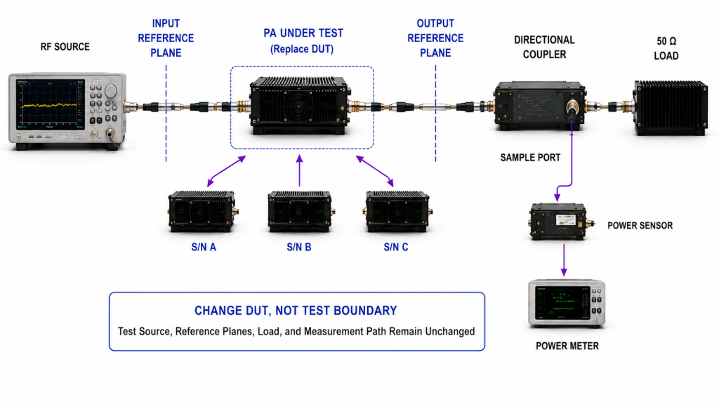
These normally include:
- Frequency
- Actual input drive
- Vdc
- RF load
- Cold-state or stabilized hot-state condition
- Test duration where thermal state matters
- Measurement reference plane
- Cable and fixture correction
- Instrument setup
Input drive is especially important.
If one module receives more RF input than another, the resulting output difference cannot be interpreted as clean unit-to-unit gain evidence.
Fixed-Input Gain Comparison
For batch gain consistency, the input drive is held constant and the resulting gain is compared across the tested units under the same defined conditions.
This method answers one specific question:
When multiple modules receive the same input under the same test boundary, how closely does their measured gain match?
The thermal state must also be consistent. A cold-state measurement shortly after startup should not be compared directly with a stabilized hot-state measurement if thermal change affects the result.
The measurement plane must also remain fixed. One module should not be evaluated at the PA output connector while another result includes an additional cable, adapter, attenuator, or other RF-path loss unless those differences are explicitly corrected.
Correction settings require the same discipline. Cable, connector, attenuator, coupler, and fixture losses can shift the reported value. If correction methods differ between units, part of the apparent batch variation may come from the test setup rather than from the amplifiers.
Target-Output and Full-Power Testing Answer a Different Question
Target-output and full-power testing should not be merged into the fixed-input batch gain limit.
Those tests may allow different input-drive requirements between modules and may need to evaluate achieved output, compression, DC behavior, thermal state, and protection at the defined operating condition.
The results should therefore be reviewed separately from fixed-input batch gain consistency.
The purpose of the batch gain comparison is not to create an unnecessarily complex measurement study. It is to ensure that every compared result represents the same engineering question.
5. What Proves Batch Gain Consistency
A batch-average gain curve is not enough if it hides the individual modules that fall outside the allowed variation.
At each required frequency, unit-to-unit variation can be reported by comparing the measured gain of the tested units under the same defined test boundary.
For example, the record may show the highest and lowest measured gain at a required frequency, or compare each result against an agreed nominal or reference window. The exact acceptance method should be defined before the batch is tested.
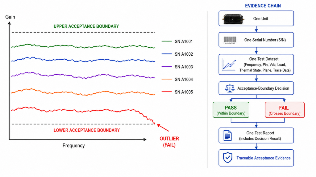
The approval record should also state:
- Total batch quantity
- Number of modules tested
- Per-unit testing or sampling ratio
- Module S/N for tested units
- Required frequency points
- Actual input drive
- Vdc
- Thermal state
- Defined test regime
- Individual gain values or identifiable traces
- Gain-flatness result where required
- Maximum unit-to-unit variation
- Pass/fail boundary
- Retest or expanded-sampling rule
If sampling is used instead of testing every module, the buyer and supplier should agree in advance what happens when a tested unit fails.
When full-power output is also part of lot release, RF power tolerance should define the output-power acceptance rule separately from batch gain consistency.
The record should identify units outside the agreed acceptance boundary rather than hiding them inside an average.
For acceptance purposes, an outlier should be identified against the agreed decision boundary rather than by visual distance from the batch average. A unit outside that boundary should follow the predefined retest, expanded-sampling, sorting, or rejection rule.
When interchangeability with the original delivery is required and the project acceptance conditions remain unchanged, a replacement or later-production module should be evaluated against the same project-defined gain boundary used for the accepted batch.
A new S/N does not need to reproduce one historical trace exactly; it needs to remain within the agreed frequency, input-drive, thermal-state, measurement-plane, and acceptance boundaries.
| What the Buyer Sees | What Can Be Missed | What to Check Before Approval | Why It Matters |
|---|---|---|---|
| One good engineering-sample curve | Unit-to-unit variation | Compare multiple S/N-linked records | Shows whether one sample represents the delivered population |
| Good sample gain flatness | Absolute gain may still vary between units | Check flatness and unit-to-unit variation separately | Protects channel-to-channel consistency |
| One batch-average curve | Individual outliers | Review identifiable unit results and maximum deviation | Prevents an average from hiding a weak unit |
| Same model number | Production variation | Review batch-specific evidence | Reduces unexpected recalibration |
| Similar fixed-input gain | Different near-full-power behavior | Request separate target-output or full-power evidence | Avoids treating gain data as full-power proof |
| First delivery passes | Replacement or later-batch drift | Preserve the original project acceptance boundary when interchangeability is required | Supports future replacement and replenishment |
When S/N-linked reporting is specified in the agreed acceptance plan, RF SKYPOWER batch records can associate the tested module S/N with the recorded gain or gain-flatness result and its defined test conditions.
The evidence should represent the tested delivered units rather than only an engineering sample or an anonymous batch-average curve.
An RF PA test report before shipment can then connect model identification, individual S/N, RF test results, applicable operating limits, and the final recorded result.
This creates a more useful evidence chain:
One Unit → One Serial Number → One Test Dataset → One Test Report → Traceable Acceptance Evidence
What the RFQ Must Define Before Batch Gain Testing
“Good gain consistency” is not a measurable acceptance requirement.
Before testing starts, the RFQ should define the batch-specific comparison boundary clearly enough that both buyer and supplier know what will be measured and how the result will be judged.
At minimum, define:
- The comparison regime
- Total batch quantity
- Per-unit test requirement or sampling quantity
- Required frequency points
- Cold-state, hot-state, or other agreed thermal boundary
- The unit-to-unit gain acceptance rule
- The rule for failed samples, retest, or expanded sampling
- Replacement-module or later-batch requirement
- Required S/N-linked report format
If the project also requires a formal gain-tolerance calculation, frequency-specific tolerance window, reference-plane definition, or measurement decision rule, those details should be defined in the dedicated gain-tolerance requirement rather than recreated here.
Likewise, full-power output consistency should remain a separate acceptance requirement.
For a custom project, these batch requirements can be included with the required frequency range, gain, target output state, thermal condition, control interface, and report requirement when defining custom RF power amplifier modules.
Batch Gain Acceptance Checklist
| RFQ Item | Customer Input Needed | What It Confirms |
|---|---|---|
| Batch and test quantity | Total delivery quantity, per-unit testing, or sampling ratio | Defines how much of the delivery is represented |
| Gain acceptance boundary | Allowed unit-to-unit variation | Defines the batch-consistency decision |
| Gain-flatness requirement | Allowed within-unit variation across frequency, if required | Keeps flatness separate from batch spread |
| Test frequencies | Required low, mid, high, or project-critical points | Defines where modules are compared |
| Comparison regime | Fixed-input gain or other agreed method | Prevents different test questions from being mixed |
| Supply and thermal boundary | Vdc, thermal state, test duration if applicable | Makes unit-to-unit comparison repeatable |
| Report evidence | Individual values or traces linked to module S/N | Supports traceability |
| Replacement requirement | Acceptance boundary for interchangeable spare or later-production modules | Supports future module replacement |
| Failed-sample rule | Retest, expanded sampling, sorting, or rejection | Defines what happens when one result fails |
FAQ
Should every RF PA module receive an individual gain report?
It depends on the project risk, batch quantity, and acceptance plan. A project may require per-unit S/N-linked records, while another may use an agreed sampling plan. If sampling is used, the sampling quantity and failed-sample response should be defined before testing.
Can one batch-average curve be used for approval?
A batch-average curve can support a summary, but it should not be the only evidence when unit-to-unit consistency is part of acceptance. The buyer should still be able to determine the tested population, individual variation, maximum deviation, and whether any tested unit falls outside the agreed boundary.
How should replacement modules or later batches be checked?
When interchangeability with the original delivery is required and the project acceptance conditions remain unchanged, replacement or later-production modules should be evaluated against the same project-defined gain boundary. The objective is not to reproduce one historical trace exactly, but to remain within the agreed frequency, input-drive, thermal-state, measurement-plane, and acceptance limits.
Conclusion
One RF PA engineering sample cannot prove batch gain consistency because it contains no evidence about unit-to-unit variation in the delivered population.
A defensible batch comparison requires multiple identifiable results—or an agreed sampling plan—measured under the same relevant frequency, input drive, Vdc, load, thermal state, correction method, measurement plane, and test regime. Gain flatness, batch gain consistency, and full-power output remain separate acceptance questions and should not be collapsed into one vague tolerance.
For a batch RF PA RFQ, provide the required frequency points, fixed-input or other agreed test regime, defined input-drive requirement, gain acceptance window, Vdc, RF load, thermal state, total batch quantity, per-unit or sampling requirement, replacement-unit boundary, and S/N-linked report requirement.
Contact Us with these RFQ and acceptance requirements before production approval. RF SKYPOWER can then review the requested batch gain acceptance boundary and the required S/N-linked evidence structure before production delivery.