










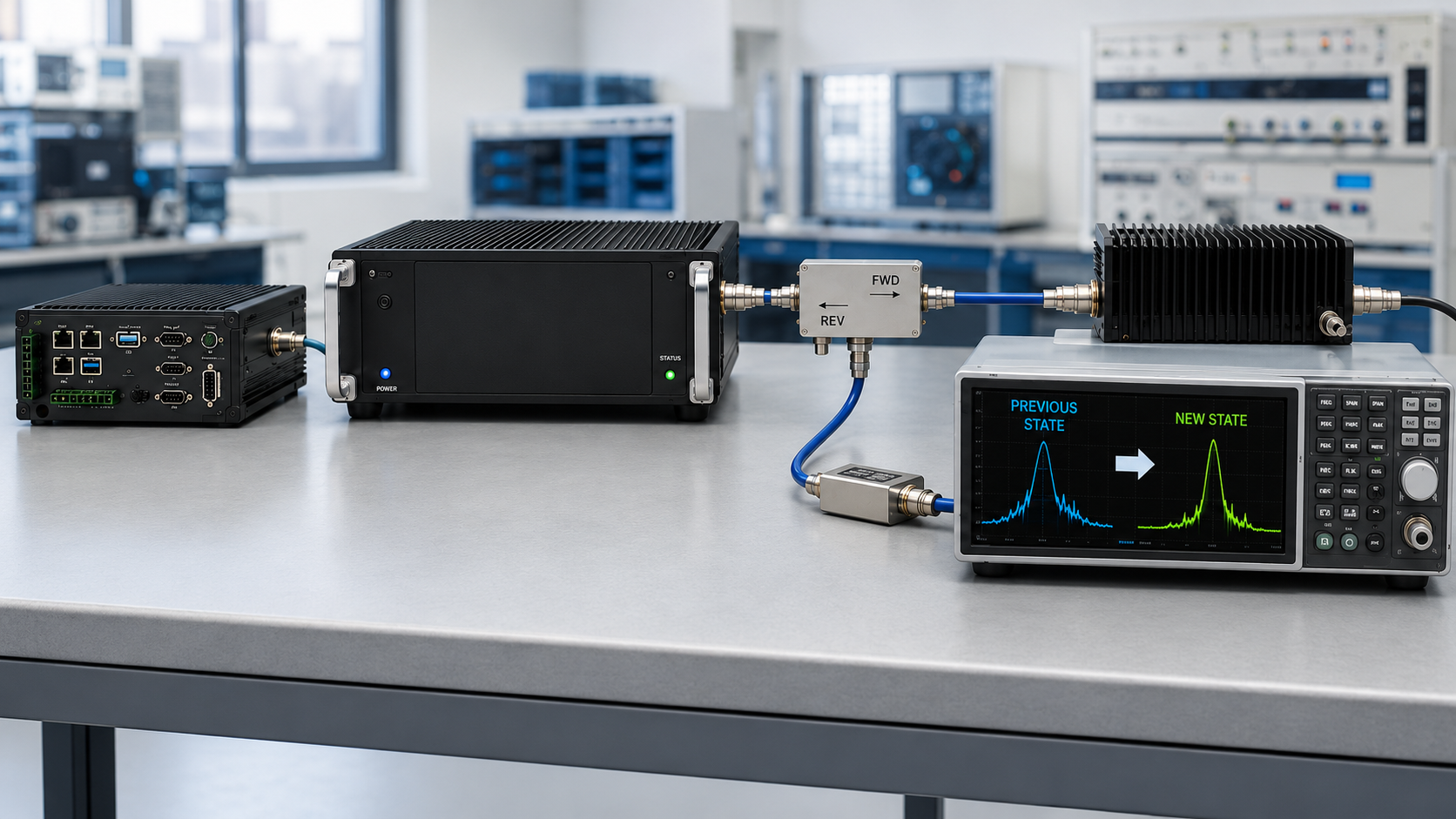
An RF PA can support every required operating frequency while the project’s RF PA frequency switching requirement remains unproven. A controller may receive a successful response to a frequency-change request without proving that the required RF state has actually changed or that the system is ready to accept the new operating condition.
That gap matters when a C-UAS system must move between frequency states through one PA, several RF paths, or multiple control and RF-state-changing elements. Static frequency coverage says little about whether the transition itself is controlled, measurable, and repeatable.
So before integration, what evidence proves that a requested transition from one frequency state to another actually completed—and how should the system distinguish a successful transition from a controlled failure?
1. What Frequency Coverage Does Not Prove About Switching
A published frequency range defines the stated operating coverage under its applicable specification or verification boundary.
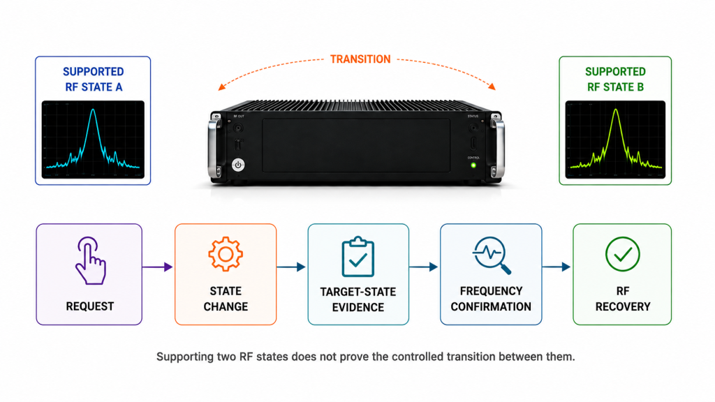
It does not by itself prove dynamic switching behavior between two required frequency states.
A module may support frequency A and frequency B while the project still lacks evidence for:
- the transition from A to B;
- the return transition from B to A;
- the element that initiates the transition;
- the RF-state-changing element or elements that must respond;
- transition timing;
- target-frequency confirmation;
- RF output recovery;
- or failure handling.
Static coverage and dynamic transition performance answer different questions.
For broader static frequency-range qualification, see RF PA frequency-range verification.
A useful switching requirement therefore starts with an actual transition boundary:
Start state → requested target state → transition action → target-state evidence → frequency confirmation → RF recovery → successful acceptance or controlled failure
That sequence does not mean every system must use the same command interface, PA architecture, RF switch, or synthesizer.
It means the project should define what must happen between the known starting state and the final accepted state.
2. Define the Frequency-Transition State Boundary
RF PA frequency switching should be treated as a controlled state transition rather than inferred from one command response.
The first step is to identify both who requests the transition and which RF-related elements actually have to change state.
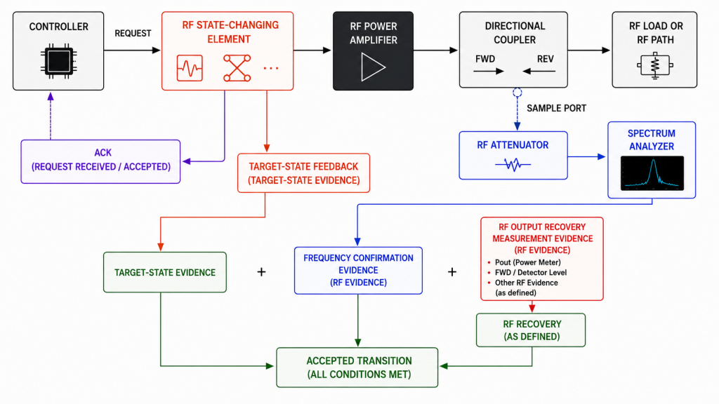
| Transition Item | What Must Be Defined |
|---|---|
| Start frequency / preset | RF state before the transition begins |
| Target frequency / preset | Requested RF state after the transition |
| Transition request source | Controller, host, processor, SDR, GPIO logic, or other element that initiates the request |
| RF-state-changing element(s) | PA preset logic, synthesizer, SDR, RF switch, tuner, signal source, or other element whose state must change to produce the requested RF configuration |
| Transition trigger | Command, preset request, GPIO event, system action, or another agreed trigger |
| RF mute requirement | Whether RF inhibit / mute is required during the transition |
| Timing start event | Event from which the specified timing metric is measured |
| Completion event | Event that ends the specified timing metric |
| Frequency-confirmation method | How the requested RF frequency state is verified |
| RF recovery criterion | What RF condition must be restored after the transition |
| Failure / timeout state | What happens if the requested transition does not complete |
| Repetition requirement | How many transitions are required by the agreed verification plan |
RF mute is project-defined
A frequency transition does not universally require the same mute sequence.
Whether RF must be inhibited during the transition depends on the approved:
- RF architecture;
- frequency-setting method;
- switching path;
- protection strategy;
- controller behavior;
- and acceptance requirement.
Where the approved architecture requires RF mute, a transition may include:
- request or enter the defined RF-inhibit state;
- verify the required inhibit condition;
- apply the new RF state;
- confirm the requested target state;
- restore RF permission;
- verify the required RF output recovery condition.
Where the architecture does not require RF mute, the acceptance sequence should reflect that design rather than force an unnecessary step.
The engineering requirement is not “always mute.” It is to define and verify the state transition required by the actual system architecture.
Keep protocol-state evidence separate from RF-frequency evidence
ACK, READY, target-state feedback, frequency confirmation, and RF recovery may all be useful, but they do not automatically prove the same thing.
For example:
- ACK / OK may show that the interface received or accepted a request according to its defined protocol behavior;
- READY may satisfy a defined controller-state requirement if the approved interface specification assigns that meaning;
- target-state feedback may show that a controlled device reports the requested preset or configuration;
- frequency confirmation verifies the requested RF frequency state according to the agreed observation or measurement method;
- RF output recovery shows that the required RF output condition has returned at the stated measurement boundary.
A control-status flag can satisfy a controller-state acceptance requirement when the approved interface specification defines that relationship.
If acceptance requires verification of the actual RF frequency, however, use the agreed RF-frequency observation or measurement method rather than treating ACK or READY alone as physical frequency evidence.
3. How to Define End-to-End Frequency-Switching Time
One switching-time number is meaningful only when its measurement boundary is defined.
A project may need to distinguish:
- command-transmission latency;
- command-acknowledgement latency;
- configuration-completion latency;
- frequency-settling time;
- RF output recovery time;
- or end-to-end system transition time.
These are not automatically the same metric.
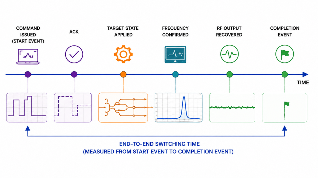
If end-to-end frequency-switching time is an acceptance parameter, define:
- the start event;
- the completion event;
- the observation point for each event;
- the measurement timebase;
- the initial frequency state;
- the target frequency state;
- whether RF mute is included in the interval;
- the frequency-confirmation requirement;
- and the RF recovery criterion required at completion.
For example, one project may define completion only after:
- the requested RF state is confirmed; and
- the required RF output condition has recovered.
Another project may intentionally define a different boundary.
The important point is to define the timing metric before comparing switching-time results.
For detailed treatment of command, state-completion, and RF-ready timing boundaries, see AT command timing.
Do not use ACK latency as end-to-end switching time
An ACK can be useful control evidence, but it should not be treated as end-to-end RF switching time unless the approved measurement definition explicitly uses that event as the completion boundary for the metric being reported.
A command may be acknowledged before:
- the target state is applied;
- the required RF frequency is verified;
- an RF switch or synthesizer has completed its transition;
- RF permission has been restored;
- or the required RF output has recovered.
The timing label must match the event actually being measured.
4. How to Verify Multi-Path Switching Completion
A C-UAS architecture may require one transition request to affect several controlled paths or RF-state-changing elements.
In that case, the acceptance plan should define which paths are required for a successful transition.
Possible rules may include:
- every commanded active path must reach its target state;
- only one specified active path is required;
- a backup path may remain inactive;
- or a non-required path may be excluded from the current transition.
The successful completion rule should be separate from the failure-handling rule.
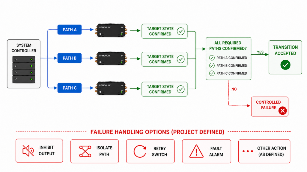
Successful transition and controlled failure are not the same result
If the acceptance rule requires all commanded paths to reach their target states, the transition should pass only when every required path satisfies its defined completion criteria.
If one required path does not complete, an approved:
- inhibit;
- isolation;
- retry;
- fault;
- or other controlled state
may demonstrate that the failure-handling logic behaved correctly.
But that outcome should be recorded as a controlled failure outcome, not as a successful frequency transition.
This distinction prevents a safe shutdown or isolation event from being misreported as a passed switching test.
Keep path identity in the evidence
Multi-path evidence should make it possible to determine which observation belongs to which controlled path.
Useful identifiers may include:
- PA or module S/N;
- channel or path ID;
- start frequency;
- target frequency;
- transition request source;
- relevant RF-state-changing element;
- controller or firmware version where materially relevant;
- command timestamp;
- target-state timestamp;
- frequency-confirmation result;
- RF recovery result;
- timeout or alarm state.
A generic READY line without source identity may be insufficient when several modules or channels can report similar states.
For wider status-source and channel-mapping questions, see RF PA status feedback.
Failure handling is part of the transition definition
A failed transition should not leave the controller guessing whether the affected RF path is usable.
The approved transition logic should define what happens when, for example:
- no response is received;
- the target state is not confirmed;
- RF-frequency confirmation fails;
- RF output does not recover;
- a required path remains incomplete;
- or a timeout expires.
The resulting state may include inhibit, retry, isolation, fault reporting, or another project-defined response.
There is no universal failure strategy.
The acceptance requirement should therefore distinguish:
- successful transition criteria; and
- controlled failure behavior.
Both may need verification, but they are not the same pass condition.
5. What Evidence Proves a Frequency Transition Completed
No single control message should be asked to prove more than it actually shows.
A useful transition record separates the main events in the switching chain.
| Transition Event | What It Can Support | What It Does Not Prove by Itself | Typical Evidence |
|---|---|---|---|
| Command issued | Controller requested a transition | Command was received or applied | Command log, timestamp, target state |
| Command acknowledged | Interface reported command receipt / acceptance according to its definition | Requested RF frequency is physically active or RF has recovered | ACK / response with timestamp |
| Target state applied | Controlled element reports the requested preset or configuration | Actual RF frequency unless the approved acceptance method explicitly uses that state as the required evidence | Device state / register / status evidence |
| Frequency confirmed | Requested RF frequency state is verified by the agreed method | Required RF output level or complete transition acceptance | RF-frequency measurement or other project-approved frequency evidence |
| RF output recovered | Project-defined RF recovery criterion is met at the stated measurement boundary | Requested RF frequency unless frequency verification is part of the same approved measurement | Pout, FWD, detector output, or other agreed RF evidence |
| Transition accepted | All project-defined successful completion criteria are satisfied | Compliance outside the defined transition boundary | Combined transition dataset |
| Controlled failure state entered | Approved failure-handling logic reached the defined safe / controlled state | Successful completion of the requested transition | Fault, inhibit, retry, isolation, or alarm evidence |
| Alarm state reported | Monitoring or control logic reported or latched a defined alarm state | Physical root cause has been independently confirmed | Alarm / fault log, source ID, timestamp |
Frequency confirmation should identify what was actually observed
The report should state what evidence was used to verify the requested frequency state and where that observation was made.
A controller-reported target preset and an RF-frequency measurement are different evidence types unless the approved acceptance method explicitly defines one of them as sufficient for the decision being made.
The project does not have to use one universal instrument or verification method.
It does need to make the evidence boundary clear.
RF recovery should use a defined pass criterion
RF presence alone should not automatically be treated as successful recovery.
RF output recovery should be judged against the project-defined RF quantity, threshold, timing condition, and measurement reference plane.
Depending on the project, the recovery criterion might use:
- Pout;
- FWD;
- detector level;
- another RF quantity;
- or a combination of agreed evidence.
A recovered RF quantity still does not independently prove that the output is at the requested frequency unless the approved measurement method verifies both conditions.
An alarm state is evidence of a reported state, not the physical root cause
If a switching attempt activates an alarm, the record should identify:
- the alarm source;
- timestamp;
- relevant path or module;
- transition state;
- and the RF / control observations surrounding the event.
An active alarm shows that the monitoring or control system reported or latched its defined alarm state.
It does not by itself prove which physical condition caused the transition to fail.
Repeatability requires repeated transitions
One successful transition documents one observed transition.
It does not automatically establish switching repeatability.
If repeatability is part of acceptance, the RFQ or test plan should define:
- which transition pairs must be repeated;
- how many repetitions are required;
- whether both transition directions are included;
- which timing and RF criteria must pass each time;
- and what evidence scope applies.
When unit-level switching evidence is required, the applicable transition dataset should remain linked to the delivered S/N.
A suitable traceability chain is:
One Unit → One Serial Number → One Switching Dataset → One Test Report → Traceable Acceptance Evidence
If the project uses batch-, configuration-, or qualification-level switching evidence instead, the record should remain identified according to that actual scope.
For the broader shipment-release evidence structure, see the C-UAS RF PA acceptance checklist.
6. How to Define RF PA Frequency Switching in the RFQ
The RFQ should not ask only:
“Does the RF PA support frequency switching?”
That question does not define what transition must be demonstrated.
Instead, define the actual switching and acceptance boundary.
RF PA Frequency Switching Checklist
| RFQ Item | Customer Input Needed |
|---|---|
| Start frequency / preset | Required initial RF state |
| Target frequency / preset | Required target RF state or transition pair |
| Required transition direction | A → B, B → A, or other required sequence |
| Transition request source | Controller, host, processor, SDR, GPIO logic, or other element that initiates the transition |
| RF-state-changing element(s) | PA preset logic, synthesizer, SDR, RF switch, tuner, signal source, or other element whose state must change |
| Command / control interface | AT, UART, GPIO, SPI, Ethernet, preset control, or project-defined interface |
| Transition trigger | Event that initiates the transition |
| RF mute requirement | Required / not required / architecture-defined |
| Timing metric | Command latency, state completion, RF recovery, end-to-end time, or another defined metric |
| Timing start event | Exact event that begins the specified timing interval |
| Completion event | Exact event that ends the specified timing interval |
| Timebase | Clock or measurement system used for timing evidence |
| Frequency confirmation | Method and observation point used to verify the requested RF frequency state |
| RF recovery criterion | Required RF quantity, threshold, timing condition, and measurement reference plane |
| Timeout | Maximum permitted interval where applicable |
| Successful transition rule | Conditions that must be satisfied for the requested transition to pass |
| Failure-state rule | Required inhibit, retry, isolation, alarm, or other approved controlled-failure behavior |
| Path / module count | Number and identity of controlled paths involved in the transition |
| Required repetitions | Number of transitions used for the agreed repeatability check |
| Relevant version identity | Controller / firmware / configuration version where materially relevant |
| DC condition | Project-defined Vdc or other DC boundary where it materially affects switching or recovery |
| Evidence scope | Unit, batch, configuration, qualification, or other agreed scope |
| S/N linkage | Required where unit-level switching evidence is part of acceptance |
Only include conditions that materially affect the project decision.
The goal is not to create the longest switching specification.
The goal is to prevent different suppliers, firmware versions, controllers, or test teams from using the same phrase—frequency switching time—for different transition boundaries.
FAQ
Does RF PA frequency coverage prove frequency-switching capability?
No—not by itself.
Frequency coverage establishes the stated operating range under its applicable specification or verification boundary.
Dynamic switching additionally requires a defined transition between required RF states and the evidence needed to verify its timing, target-frequency state, RF recovery, and pass or failure outcome.
Does ACK or READY prove that the requested frequency is active?
Not by itself.
An ACK or READY signal can satisfy a defined controller-state requirement when the approved interface specification assigns that meaning.
If acceptance requires verification of the actual RF frequency, use the agreed RF-frequency observation or measurement method rather than treating ACK or READY alone as physical frequency evidence.
Must RF output always be muted during a frequency change?
No universal mute rule should be assumed.
Whether RF mute is required depends on the approved RF architecture, switching method, protection strategy, and system requirement.
If mute is required, its entry and release conditions should be included in the transition definition.
What evidence proves an end-to-end frequency transition passed?
A successful transition should satisfy the project-defined start state, target state, timing boundary, frequency-confirmation requirement, RF recovery criterion, and successful completion rule.
If a required transition fails but the system enters an approved inhibit, isolation, retry, or fault state, that can prove correct failure handling without turning the failed transition into a successful pass.
Where repeatability or unit-level evidence is required, the applicable repetitions and S/N linkage should also be defined.
Conclusion
RF PA frequency switching is verified only when the required transition is judged against a defined start state, target state, transition boundary, timing metric, frequency-confirmation method, RF-output recovery criterion, and successful completion rule.
Frequency coverage alone does not prove dynamic switching. ACK or READY may prove a defined control state, but they should not be treated as physical RF-frequency evidence unless the approved acceptance method explicitly establishes that boundary. A recovered RF quantity does not independently prove the requested frequency, and a controlled failure state should not be reported as a successful transition.
Once the switching boundary is defined, a custom RF power amplifier module can be reviewed against the required RF states, control interface, transition elements, timing boundary, frequency-confirmation method, RF recovery requirement, failure behavior, and acceptance evidence.
For frequency-switching review, provide the required start and target RF states, transition request source, RF-state-changing elements, command interface, transition trigger, timing start and completion events, timebase, RF mute requirement, frequency-confirmation method, RF recovery quantity and reference plane, successful transition rule, timeout and controlled-failure rule, required repetitions, path or module count, relevant controller or firmware version, project-defined DC condition, evidence scope, and required S/N-linked test evidence where unit-level acceptance applies.