


Nominal frequency range can mislead C-UAS RF PA selection because RF Power Amplifier Frequency Range describes where a module is designed to operate, not where the installed system can always deliver usable RF output. A 300–1700MHz or 2000–6000MHz label may look like a complete answer during RFQ comparison, but it can hide weak points after output power, gain behavior, feeder loss, antenna VSWR, cabinet heat, DC supply, duty cycle, and protection logic are included.
The central conflict is simple: nominal frequency band answers where the PA is designed to operate, but effective frequency band answers where the installed C-UAS system can still deliver stable RF energy. For a fixed-site project, the real selection question is not “Is the frequency inside the rated band?” The better question is “Can this frequency still meet the required output, thermal, load, and test conditions after installation?”
1. What Is RF PA Frequency Range?
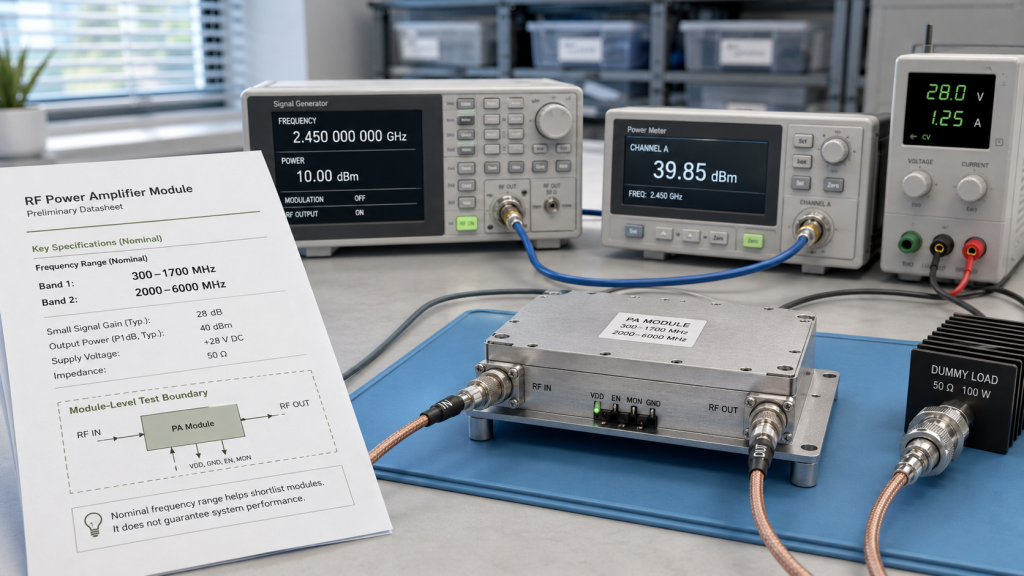
Nominal RF Power Amplifier Frequency Range means the frequency span a PA module is designed and tested to support under defined module-level conditions. It is a necessary screening parameter, but it does not prove equal output, equal gain, equal efficiency, or equal field behavior at every point inside the rated span.
How Should Engineers Read the Datasheet Line?
A datasheet range such as 300–1700MHz or 2000–6000MHz helps you shortlist RF Power Amplifier modules. It tells you which product family may fit the system plan before deeper output, load, thermal, and evidence review begins.
Here’s the engineering point:
- Nominal range describes module design coverage.
- Effective band describes usable installed behavior.
- Factory test conditions may not match site conditions.
- One clean center-frequency result does not prove full-band usability.
- A frequency label does not define the output reference point.
A frequency range may look correct during early band planning, especially after engineers compare the basic RF Power Amplifier frequency range against the project band plan. But approval should not stop there; the selected band still needs proof under target output, feeder path, antenna load, cabinet heat, duty cycle, and repeatable test evidence.
Key Takeaway: Nominal range helps you shortlist modules, but effective frequency behavior decides whether the installed C-UAS RF chain can be trusted.
| Wrong Assumption | Better Check |
|---|---|
| Rated band proves all points are equal | Check output and gain at target points |
| Datasheet range equals field range | Include feeder, antenna, heat, and load |
| Center frequency proves the full band | Test low edge, center, high edge, and mission points |
| Module pass equals system pass | Define the installed RF reference point |
| Wider label means safer selection | Verify usable output across project points |
This table helps you separate product screening from system acceptance instead of treating one datasheet line as final proof.
2. Why Can a Rated Wide Band Still Have Weak Zones?
A rated wide RF Power Amplifier Frequency Range can still have weak zones because output, gain, efficiency, thermal load, matching, and test evidence do not stay identical across the entire span. A wide label is useful, but it is not the same as flat, stable, usable RF behavior.
Where Do Weak Zones Usually Appear?
The same approval logic applies to both lower wideband modules and higher-frequency modules, but the weak zones are not always the same. In a 300–1700MHz RF Power Amplifier module, engineers may compare lower-band, mid-band, and upper-band behavior, while a 2000–6000MHz RF Power Amplifier module requires closer attention to connector quality, feeder loss, antenna match, and hot-state output.
The selection risk appears here:
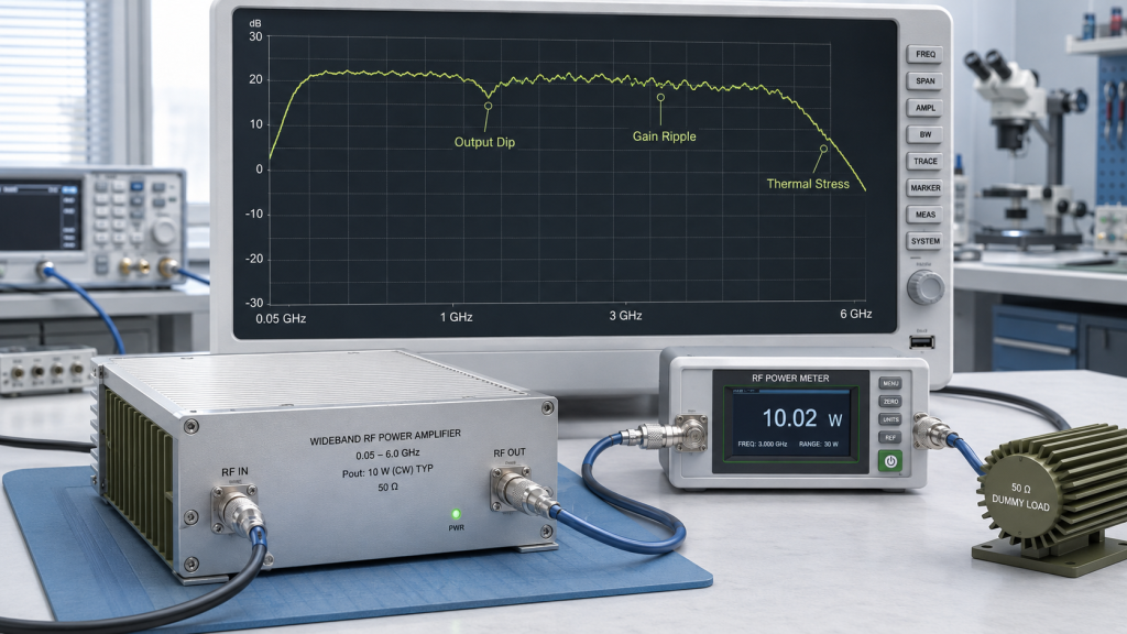
- Output may dip near certain internal matching regions.
- Gain may ripple across the band.
- Efficiency may fall at some frequencies.
- The same output target may create different current draw.
- Reflected power may rise with the real antenna path.
- Reports may only show the best-looking points.
A weak zone does not automatically mean the PA is defective. It may mean the project is using a frequency point where the PA, feeder, connector, antenna, heat, and duty cycle leave too little margin.
Key Takeaway: A wide nominal band should be treated as a coverage claim that still needs frequency-point evidence.
| Weak Zone Type | What It Can Cause |
|---|---|
| Output weak zone | Antenna-end power falls below target |
| Gain weak zone | Control calibration becomes harder |
| Thermal weak zone | Long operation causes output drift |
| Matching weak zone | VSWR alarm or reflected-power stress |
| Evidence weak zone | Procurement approves without enough data |
This table helps engineering and procurement teams ask where the band is proven, not only where it is printed.
3. How Do Fixed-Site C-UAS Conditions Change the Band?
Fixed-site conditions change RF Power Amplifier Frequency Range from a module parameter into a system-chain question. The module range stays the same on paper, but the effective frequency band can narrow after long RF paths, outdoor antennas, cabinet heat, protection hardware, and long-duty operation are added.
Why Is Fixed Infrastructure Less Forgiving?
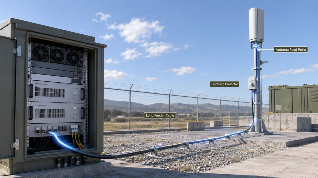
In a low-altitude security and C-UAS EW system, the RF path may include cabinet feedthroughs, lightning protection, waterproof connectors, long feeder cable, elevated antennas, and site-specific grounding. These parts do not change the datasheet label, but they can change the usable output at each frequency point.
Here’s the field reality:
- Longer feeder runs increase frequency-sensitive loss.
- Outdoor connectors add transition risk.
- Lightning protection can affect insertion loss and match.
- Cabinet heat changes long-duty stability.
- Antenna mounting changes load behavior.
- Maintenance intervals are longer than lab retest cycles.
In an airport perimeter C-UAS project, the same PA module may face longer RF routing, stricter uptime expectations, and more controlled acceptance tests than it would on a short factory bench path. The system cannot rely on a single lab condition if the deployed RF path is longer, hotter, or more complex.
Key Takeaway: Fixed-site systems turn frequency range into a site-specific RF chain decision, not a module-only decision.
| Field Condition | Selection Risk |
|---|---|
| Long feeder path | Higher-frequency output may fall at antenna end |
| Outdoor antenna | Match may shift with installation |
| Cabinet heat | Hot-state band may be narrower than cold-state band |
| Multiple transitions | Loss and VSWR uncertainty increase |
| Long-duty operation | Short sweep may miss output drift |
This table helps you identify which site variables can reduce effective RF coverage before installation begins.
4. How to Test RF PA Frequency Range
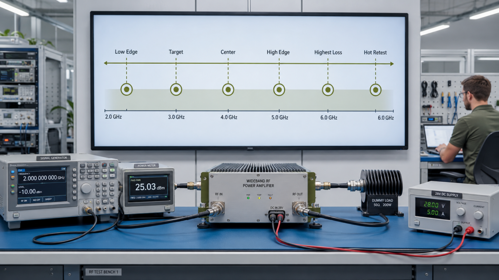
Engineers should test RF Power Amplifier Frequency Range at project-critical points, not only at a convenient center frequency. The minimum test set should include target frequencies, band edges, a center reference, the highest-loss path point, and hot-state retest points.
What Is a Practical Minimum Test Set?
A fixed-site system does not need random testing at every possible frequency point, but it does need a rational test plan. The test points should come from the authorized project frequency plan, system architecture, antenna path, and acceptance boundary.
The better check is simple:
- Test each project target frequency.
- Test the low end of the rated band.
- Test the high end of the rated band.
- Test one center reference point.
- Test the frequency with the highest expected path loss.
- Retest critical points after thermal stabilization.
- Record input drive, 28V supply, load, and output reference point.
In high-pressure FPV swarm defense cases, frequency behavior can be broad, non-uniform, and stress-dependent. A clean center-frequency test may look persuasive, but it does not prove full effective RF coverage across the points that matter.
Key Takeaway: A useful frequency test plan should follow the mission band plan, not the most convenient lab screenshot.
| Test Point | Why It Matters |
|---|---|
| Target point | Matches real system requirement |
| Low band edge | Exposes edge matching and gain behavior |
| Center point | Provides reference data |
| High band edge | Exposes loss, heat, and connector stress |
| Highest-loss point | Shows antenna-end risk |
| Hot-state point | Shows sustained usable behavior |
This table gives engineers a practical way to turn nominal frequency range into measurable acceptance points.
5. Why Does Output Power Vary Across the Band?
Output power varies across RF Power Amplifier Frequency Range because the amplifier device, matching network, PCB path, drive condition, load, supply, and heat state are not identical at every frequency. This variation can turn a rated band into a smaller usable band.
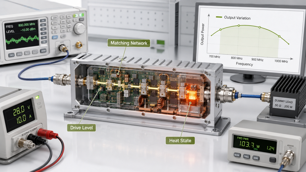
What Changes Inside and Around the PA?
Wideband PA design is a balance between output power, gain, bandwidth, efficiency, stability, protection, and manufacturability. At some frequencies, the module may need more drive, draw more current, produce more heat, or operate closer to compression.
Here’s the practical risk:
- A strong output point may hide weaker neighboring points.
- Gain ripple may affect calibration.
- Efficiency loss may create thermal stress.
- Higher current draw may expose supply margin limits.
- Frequency-sensitive loss may reduce antenna-end power.
- A clean PA-port result may not survive the installed path.
Band-edge behavior is often where center-point assumptions fail. Engineers should include band-edge data when judging whether the rated frequency range remains effective at the low and high ends.
Key Takeaway: Output power across the band must be treated as measured behavior, not assumed behavior.
| Symptom | Possible Cause |
|---|---|
| Lower power at one point | Gain ripple or matching pressure |
| More heat at same target output | Lower efficiency at that frequency |
| Alarm near antenna connection | VSWR or reflected power issue |
| Good PA-port power but weak field result | Feeder or antenna-end loss |
| Different repeat-test results | Drive, supply, or thermal boundary changed |
This table helps you trace frequency-related output changes without blaming the wrong component too early.
6. How Feeder Paths Affect RF PA Frequency Range
Antenna and feeder behavior can narrow RF Power Amplifier Frequency Range in the installed system because power must survive the real RF path and remain safe under the real antenna load. The PA may be rated correctly, while the system path may not preserve enough power or margin.
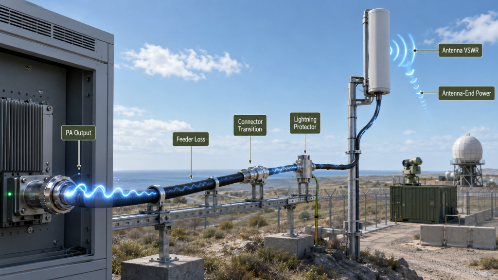
Why Does the Antenna End Matter More?
A fixed-site C-UAS system usually cares about power that remains after the RF path, not only wattage at the PA output port. Feeder loss and connector loss should be reviewed before deciding whether a point is truly usable at the antenna end, especially in border and coastal C-UAS deployments.
This is where system integrators should pay attention:
- Cable length affects insertion loss.
- Connector quality affects repeatability.
- Lightning protection adds path loss and matching risk.
- Antenna VSWR changes reflected power.
- Outdoor routing can change mechanical stress.
- Waterproof joints can add repeatability risk.
A PA that performs well on a 50Ω dummy load may behave differently with a real antenna. If the antenna match is poor at certain points, reflected power can rise and protection logic may derate, alarm, or shut down output. Engineers should review feeder and connector loss before deciding whether a frequency point is truly usable at the antenna end.
Key Takeaway: Effective frequency band depends on the installed RF path and antenna load, not only the PA output connector.
| Installed Path Item | How It Can Narrow Effective Band |
|---|---|
| Long feeder cable | Reduces antenna-end power |
| Adapter transition | Adds loss and mismatch |
| Lightning protector | Changes insertion loss and match |
| Broadband antenna | May not match equally at all points |
| Weatherproof joint | Adds repeatability risk |
This table helps you review the RF chain as a system instead of approving the PA in isolation.
7. Why Can Heat Make Some Frequencies Unusable?
Heat can make part of RF Power Amplifier Frequency Range unusable because hot-state efficiency, output stability, and protection behavior may differ from cold bench-test results. A frequency that passes a short sweep may become marginal after the cabinet reaches operating temperature.
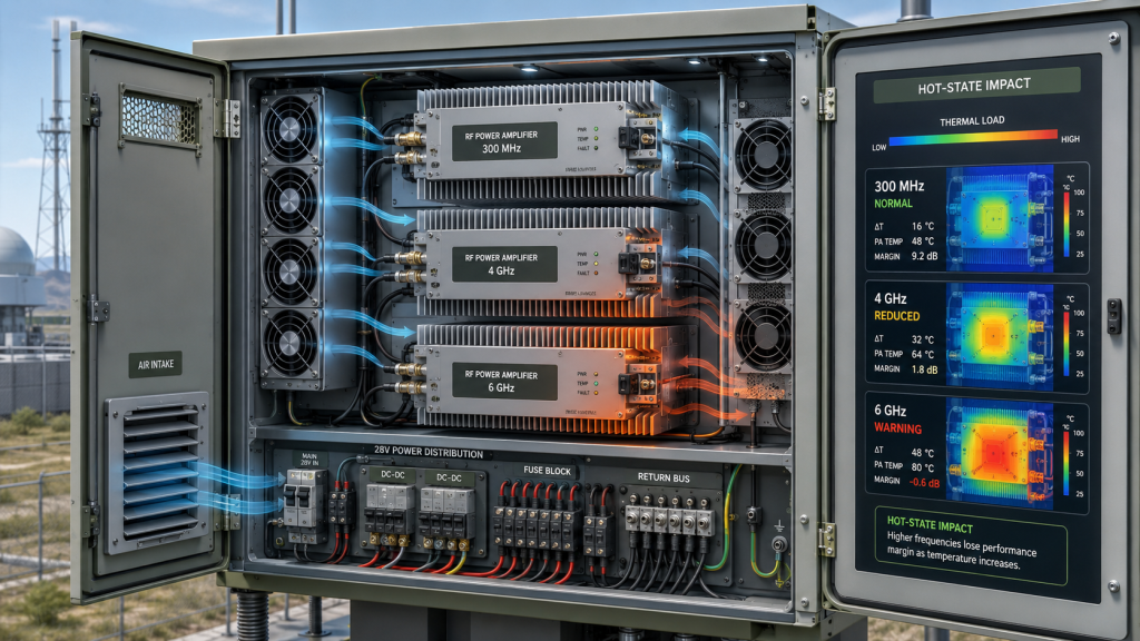
What Changes During Long Operation?
Different frequencies can create different thermal loads at the same target output. If one point needs more current, operates at lower efficiency, or faces worse matching, it may generate more heat during long-duty use.
Here’s the field reality:
- Outdoor cabinets can trap heat.
- Multiple modules can raise shared thermal load.
- Fan or heatsink limits may appear after hours.
- Dust and restricted airflow can reduce cooling margin.
- Thermal protection can change usable output.
- Summer cabinet temperature can invalidate room-temperature assumptions.
Cold-state testing is useful, but it is not enough for fixed-site C-UAS approval. Critical points should be checked after thermal stabilization, especially where output, current, gain, or reflected power already looks close to the limit.
Key Takeaway: A real effective band must be proven under the thermal condition the system will actually face.
| Thermal Condition | What to Check |
|---|---|
| Cold bench sweep | Initial output and gain behavior |
| Warm cabinet operation | Output drift and current rise |
| Long-duty operation | Protection events and stability |
| Multi-module load | Shared heat accumulation |
| High ambient site | Thermal margin at target points |
This table helps buyers avoid approving a frequency range that only works under easy thermal conditions.
8. What RF PA Range and Bandwidth Mean
Frequency range, instantaneous bandwidth, and usable RF band should be separated because RF Power Amplifier Frequency Range is only one part of the C-UAS RF architecture. Mixing these terms in an RFQ can cause wrong module selection, wrong system architecture, or weak acceptance criteria.
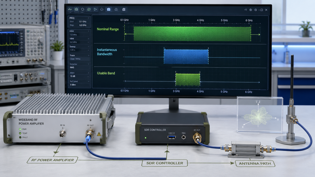
What Should Each Term Answer?
Nominal frequency range describes the total rated operating span. Instantaneous bandwidth describes how much spectrum the system can handle at one time under a specific architecture. Effective frequency band describes which points remain usable after output, heat, load, supply, and RF path are included.
The practical risk is clear:
- “300–2700MHz required” may be too vague.
- “200MHz instantaneous bandwidth” does not prove full-band output.
- “Wideband module” does not define antenna-end usable power.
- “Coverage” may mean different things to RF, software, and procurement teams.
- A system can cover a band on paper but fail a specific output point.
A vague RFQ invites a vague answer. If you only write the nominal band, suppliers may quote a module that fits the label but not the duty cycle, antenna path, thermal condition, or acceptance method.
Key Takeaway: Clean terminology prevents procurement from confusing rated coverage, real-time bandwidth, and usable installed behavior.
| Term | Question It Answers |
|---|---|
| Nominal frequency range | Where is the PA designed to operate? |
| Instantaneous bandwidth | How much spectrum is handled at one time? |
| Effective frequency band | Which points remain usable in the system? |
| Usable output | Where is enough power still available? |
| Acceptance boundary | Where and how is performance measured? |
This table helps RF and procurement teams use the same language before quotation.
9. What Proves Effective RF PA Frequency Range?
Effective RF Power Amplifier Frequency Range should be proven by repeatable frequency-point output data, gain behavior, hot-state stability, VSWR status, load condition, supply condition, and S/N-linked test evidence. A datasheet range is a claim; the test file should show where that claim remains useful.
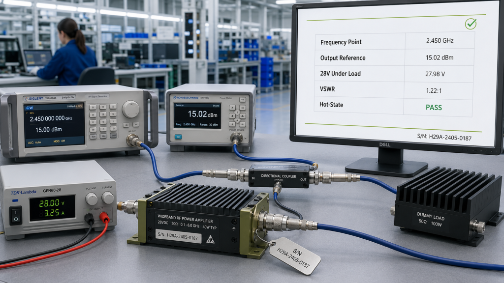
What Should the Report Actually Show?
For wideband C-UAS modules, test evidence should show more than a peak output number. Engineers should ask for data that connects the frequency point, output reference point, voltage, input drive, load condition, thermal state, and protection status.
A stronger evidence file should include:
- Frequency-point output data.
- Gain or output trend across the band.
- RF input drive level at the PA input.
- 28V supply voltage under load.
- Forward and reflected power status.
- Load and reference-point description.
- Hot-state data at critical points.
- Alarm, derating, or protection status.
- S/N-linked production records.
As a source factory for RF Power Amplifier modules and C-UAS core components, RF SKYPOWER can support early review by checking target frequency points, usable output, antenna path, cabinet thermal condition, VSWR behavior, and repeatable test evidence before final module approval.
Key Takeaway: Effective frequency band becomes credible when the report connects RF behavior to the same conditions the system will use.
| Report Field | Why It Matters |
|---|---|
| Frequency point | Prevents center-point-only proof |
| Output reference point | Separates PA-port and antenna-end claims |
| RF input drive | Shows whether output came from fair drive |
| 28V under load | Exposes supply-related output weakness |
| Load condition | Explains dummy-load vs antenna behavior |
| Hot-state data | Confirms sustained usability |
| Protection status | Shows whether output is clean or derated |
| S/N record | Supports production-unit traceability |
This table helps buyers separate attractive datasheet claims from acceptance-ready engineering evidence.
10. How to Define RF PA Frequency Range in RFQs
Engineers should define RF Power Amplifier Frequency Range in an RFQ together with target points, usable output, reference point, duty cycle, load condition, thermal condition, protection behavior, and required acceptance evidence. A short line such as “Need 300–1700MHz 100W PA” is not enough for a fixed-site C-UAS project.
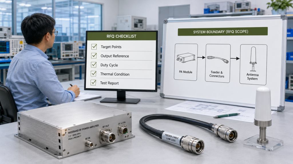
What Should the RFQ Include Before Quotation?
The RFQ should help the supplier judge whether the module, RF path, cooling, control, and test scope match the project. This reduces quotation errors and avoids choosing a module that fits the label but fails the installed condition.
Include these items before approval:
- Nominal frequency range.
- Target frequency points.
- Required output at each critical point.
- PA-port or antenna-end reference point.
- RF input drive level.
- 28V supply condition.
- Duty cycle or continuous operation requirement.
- Load, antenna, and feeder assumptions.
- Ambient or cabinet temperature.
- VSWR, temperature, and voltage protection visibility.
- Required test report format.
- Production report or S/N traceability requirement.
The final decision should not be “which module has the widest label?” It should be “which module has enough proven usable behavior under the project’s RF, thermal, electrical, load, and evidence boundaries?”
Key Takeaway: A strong RFQ turns frequency range from a catalog label into a measurable system requirement.
| RFQ Item | Why It Matters |
|---|---|
| Target frequency points | Prevents center-point-only approval |
| Output reference point | Defines PA-port vs antenna-end power |
| RF input drive | Makes output data comparable |
| Duty cycle | Separates burst test from sustained use |
| Antenna path | Captures feeder and VSWR risk |
| Thermal condition | Shows hot-state usability |
| Test report format | Makes acceptance repeatable |
This table helps engineering and procurement teams approve the same measurable requirement instead of different interpretations of one frequency label.
FAQ
Can I accept a module if my target band is inside its rated range?
Yes, but only after checking usable behavior at your target points. The rated range means the module is designed for that span, but it does not prove output, gain, heat, VSWR, and antenna-end power under your installed conditions.
How do I know if the effective frequency band is wide enough?
Check frequency-point output, gain behavior, feeder loss, antenna match, hot-state stability, and protection status. If the weakest project-critical point still meets your usable output and stability requirement, the effective band is more credible.
What should I check before approving a wideband RF PA?
You should check target frequency points, band edges, input drive, 28V supply condition, PA-port or antenna-end reference point, load condition, duty cycle, hot-state output, and S/N-linked test evidence.
Can feeder and antenna issues make a good PA look weak?
Yes, they can. A good PA may pass factory testing but show weaker installed behavior if cable loss, connector transitions, lightning protection, antenna VSWR, or outdoor routing changes the effective RF path.
When should I ask for full-band sweep data?
Ask for full-band or key-point sweep data before final module approval, especially for fixed-site C-UAS projects with long feeders, high antennas, outdoor cabinets, long-duty operation, or multi-module RF chains.
Conclusion
Nominal frequency range is a useful selection starting point, but it should not be treated as final proof of C-UAS RF PA performance. This article has shown why the effective frequency band depends on output power, gain behavior, feeder path, antenna match, thermal condition, duty cycle, protection logic, supply condition, and repeatable test evidence.
For fixed-site C-UAS systems, the best approval process starts before the cabinet is built. Prepare your target frequency points, required usable output, antenna path, operating duty cycle, hot-state condition, and report expectations before requesting final RF module approval.
RF SKYPOWER can support this review by helping system integrators compare nominal frequency range with effective frequency behavior across wideband RF Power Amplifier modules, antenna paths, protection feedback, and S/N-linked test evidence. To review your RF module requirements before selection, contact us with your target frequencies, output goals, duty cycle, and integration environment.
Field-ready C-UAS systems are built on verified RF decisions, not catalog shortcuts.