


C-UAS System EIRP should be calculated from RF PA output after RF path loss, antenna gain, antenna direction, mismatch behavior, thermal derating, and measurement boundary are included. RF Power Amplifier Output Power is the starting point of the RF chain, but it is not the final system EIRP. A 100W or 200W PA module may deliver the expected power at the PA output port, yet the installed border or coastline C-UAS system can show a different EIRP after feeder loss, connector loss, switching loss, antenna mismatch, outdoor derating, and antenna gain are included.
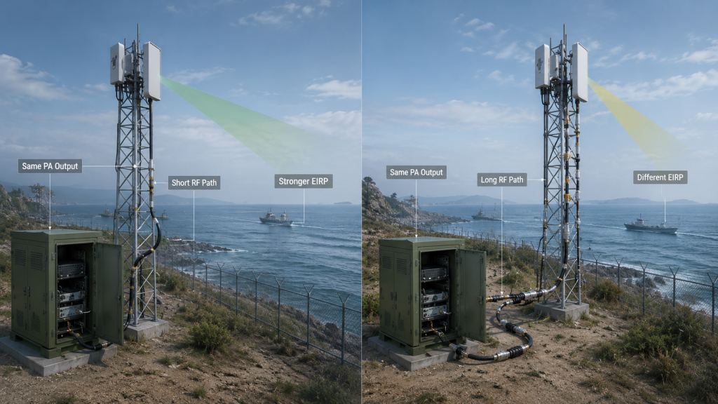
The central conflict is simple: RF Power Amplifier Output Power describes what the PA module can deliver at a defined output boundary, but C-UAS System EIRP describes the equivalent radiated power in a defined antenna direction after the installed RF chain is included. For border and coastline C-UAS projects, this difference matters because long RF paths, tower antennas, outdoor protection hardware, high-gain directional antennas, and project-defined EIRP limits can make the final system result very different from the PA watt label.
When selecting RF Power Amplifier modules for C-UAS integration, engineers should confirm how PA output becomes system EIRP after RF path loss and antenna gain are included.
1. What PA Watts Miss About C-UAS System EIRP
RF PA output power is not the same as C-UAS System EIRP because EIRP also depends on RF path loss, antenna gain, antenna direction, mismatch behavior, and the measurement boundary used in the installed system. A 100W or 200W PA module tells you where the RF chain starts, not what the system radiates after installation.
Here’s the engineering point: a PA output number is measured at a defined point, usually the PA output port or cabinet output. EIRP is a system-level result that includes what happens after that point.
What Does PA Output Actually Describe?
PA output describes how much RF power leaves the amplifier at a specified boundary. That boundary must be defined before it can be used for EIRP planning.
Common boundaries include:
- PA output port
- Cabinet output connector
- Feeder input
- Feeder end
- Antenna input
- Installed antenna direction
Before calculating EIRP, engineers should define RF power measurement points so PA-port output, cabinet output, feeder-end power, and antenna-port power are not mixed.
Why Does EIRP Need More Than Watts?
EIRP needs more than PA watts because the antenna system reshapes the final radiated result. Loss reduces the power before the antenna, while antenna gain increases equivalent power in a defined direction.
Key Takeaway: PA output is the RF chain input; EIRP is the installed antenna-direction result.
| Wrong Assumption | Better Check | Why It Matters |
|---|---|---|
| 100W PA equals 100W EIRP | Include loss and gain | Avoids false system claims |
| PA-port power is system power | Define the boundary | Prevents acceptance disputes |
| More watts always means higher EIRP | Check RF path and antenna gain | Finds real system result |
| One system number covers all directions | Review per-direction EIRP | Matches antenna pattern |
This table helps buyers separate module output from the system-level radiated-power result.
2. When Is Single-Module Power Still a Useful Starting Point?
Single-module power is still useful because C-UAS System EIRP calculation starts from RF Power Amplifier Output Power before RF path loss and antenna gain are applied. PA watts are not the final answer, but they are still the first input for power, thermal, supply, and cabinet planning.
The practical risk is clear: ignoring PA output is just as wrong as trusting it blindly. You need the PA number, but you also need the system conditions around it.
What Can PA Output Help You Decide?
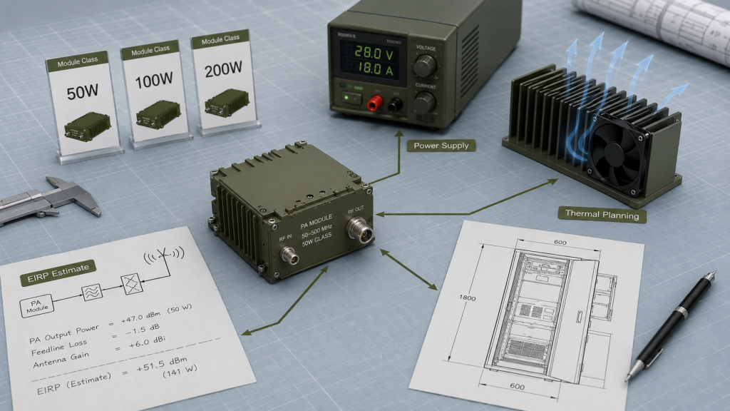
PA output helps engineers shortlist module classes and estimate system resources. It is useful early in design when the final antenna layout is still being developed.
PA output helps estimate:
- 50W, 100W, 150W, or 200W module class
- DC power supply size
- Heat dissipation requirement
- Cabinet space and airflow
- Feeder-path margin
- Antenna-port target feasibility
- Initial EIRP estimate
After 100W vs 200W RF Power Amplifier selection, engineers still need to calculate system EIRP using actual RF path loss and antenna gain.
When Does PA Output Mislead?
PA output misleads when the RF path is long, antenna gain is unknown, thermal derating is ignored, or EIRP is assumed from the module label alone.
Key Takeaway: Single-module power is useful for starting the calculation, not for ending the engineering decision.
| Use of PA Output | Useful For | Not Enough For |
|---|---|---|
| Module class selection | First screening | Final EIRP approval |
| DC and thermal planning | Cabinet design | Antenna-direction result |
| RFQ comparison | Supplier discussion | Installed system proof |
| Short-path estimate | Early planning | Border/coastline validation |
This table helps teams use PA output correctly without turning it into a false system metric.
3. How to Define C-UAS System EIRP from PA Output
C-UAS System EIRP is defined by PA output power minus installed RF path loss plus antenna gain in the target antenna direction. It should be calculated per frequency, per channel, and per antenna direction, not treated as one vague total system-power number.
Here’s the useful part: the formula is simple, but the engineering inputs behind it are not.
What Is the Basic EIRP Relationship?
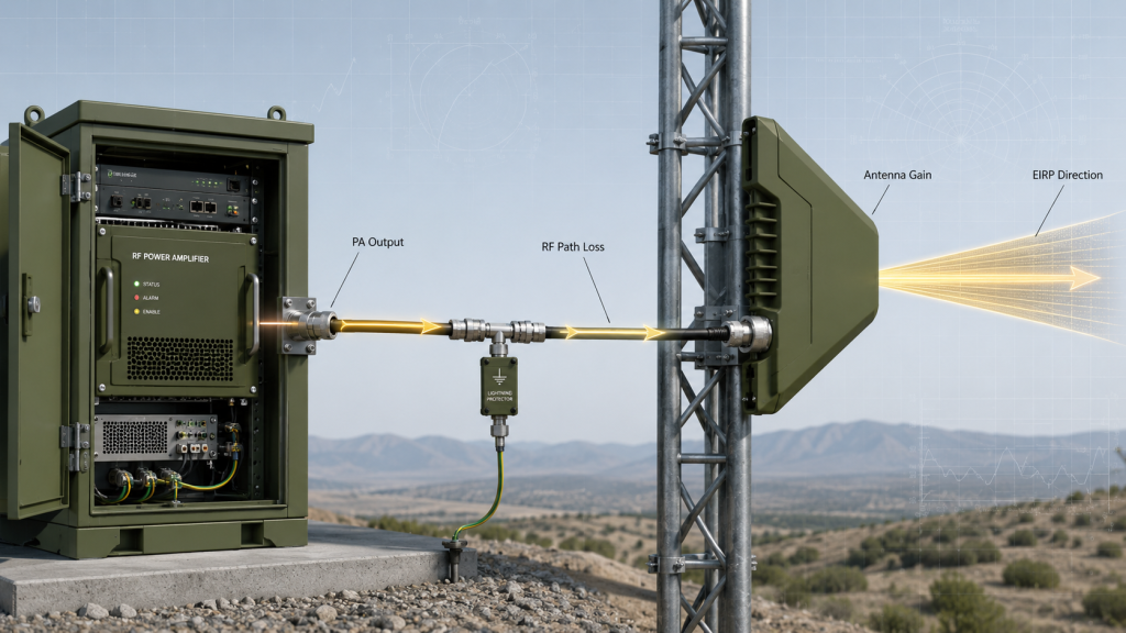
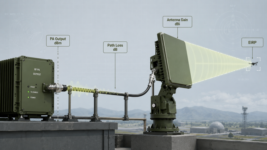
A practical engineering relationship is:
EIRP (dBm) = PA Output (dBm) − RF Path Loss (dB) + Antenna Gain (dBi)
RF path loss may include:
- Feeder cable loss
- Connector loss
- Adapter loss
- Lightning protector loss
- Waterproof joint loss
- Switch or filter loss
- Combiner or splitter loss
- Mismatch loss
- Cabinet feedthrough loss
System EIRP should subtract RF Power Amplifier feeder and connector loss before antenna gain is added to the calculation.
Why Do Antenna Gain and Direction Matter?
Antenna gain is directional. A high-gain antenna may increase EIRP toward one border or coastline sector, but it does not increase every direction equally.
Key Takeaway: EIRP is a path-level and direction-level value, not a simple restatement of PA watts.
| EIRP Input | What It Does | Common Mistake |
|---|---|---|
| PA output | Starts the power chain | Treated as final EIRP |
| RF path loss | Reduces antenna input power | Ignored as “small loss” |
| Antenna gain | Shapes directional EIRP | Treated as all-direction boost |
| Measurement boundary | Defines input value | Mixed with antenna-port data |
| Frequency point | Changes loss and gain | One point assumed for all bands |
This table helps engineers turn the EIRP formula into a real system review.
4. How Does EIRP Change Real C-UAS Effectiveness?
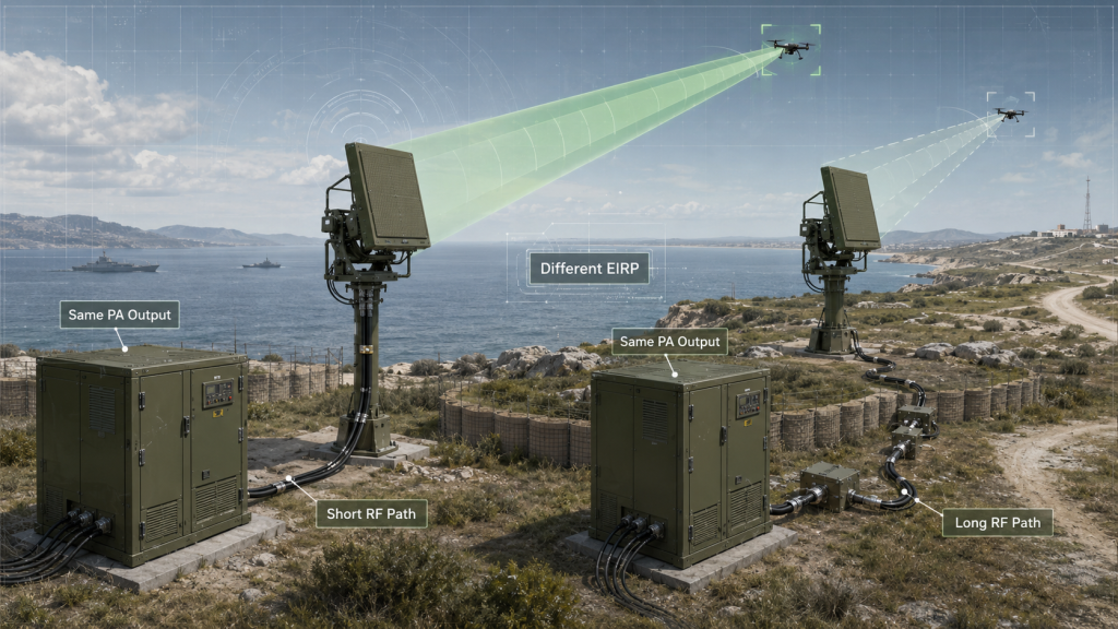
EIRP changes real C-UAS effectiveness because C-UAS System EIRP describes the RF power that the installed system can radiate toward a defined direction after path loss and antenna gain are included. It connects PA output to the final antenna-direction result that the system depends on.
Here’s the field reality: two systems with the same PA wattage may produce different EIRP if one has a shorter feeder, lower connector loss, better antenna gain, or a more suitable antenna direction.
Where Does EIRP Affect the System Review?
EIRP helps engineers evaluate the system as a complete RF chain instead of a PA module alone. It also helps procurement teams understand why two “200W systems” may not behave the same.
EIRP affects:
- Per-frequency RF margin
- Per-direction antenna performance
- Multi-site comparison
- Border or coastline sector planning
- RFQ acceptance language
- Project-defined output boundaries
- Compliance or authorization review
In Low-Altitude Security & C-UAS EW Solutions, system EIRP should be reviewed per frequency and antenna direction, not only by single-module PA wattage.
Why Is Higher EIRP Not Always Better?
EIRP must match project requirements and authorized boundaries. More EIRP can be useful in a target direction, but uncontrolled EIRP can create design, compliance, or system-control issues.
Key Takeaway: EIRP is the bridge between PA output and installed system behavior, but it must be controlled by direction, frequency, and project boundary.
| EIRP Review Point | Why It Matters | Better Question |
|---|---|---|
| Frequency-specific EIRP | Loss and gain change by band | Which points are critical? |
| Direction-specific EIRP | Antenna pattern is not uniform | Which sector is served? |
| Project boundary | EIRP may be limited | What is authorized? |
| Antenna gain | Shapes energy distribution | Is direction correct? |
| RF path loss | Reduces final power | Was loss included? |
This table helps readers judge EIRP as a controlled engineering metric, not a “bigger is always better” number.
5. What Border Sites Reveal About C-UAS System EIRP
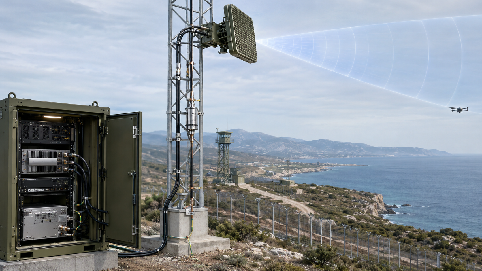
Border and coastline deployments reveal the gap between PA power and C-UAS System EIRP because long RF paths, high-gain antennas, outdoor protection hardware, and directional coverage all reshape the final radiated power. A PA module may be strong, while the installed EIRP depends on the full site architecture.
This is where the scenario matters: border and coastline projects often use long-line coverage, tower or high-point antennas, directional sectors, and outdoor RF chains exposed to wind, salt fog, humidity, heat, rain, and lightning protection requirements.
Which Field Conditions Change EIRP?
Border and coastline systems often have more RF-chain variation than a short indoor setup. That variation changes both antenna-port power and EIRP.
Common conditions include:
- Long feeder routes from cabinet to antenna
- High-gain directional antennas
- Tower, mast, or rooftop mounting
- Lightning protection and grounding
- Waterproof connectors and outdoor joints
- Multiple coastline or border sectors
- Salt fog, humidity, wind, and temperature swing
- Per-site antenna direction differences
In a border and coastline C-UAS deployment, long RF paths, high-gain antennas, and outdoor protection hardware can make system EIRP very different from PA output power.
Why Does Directional Coverage Matter?
A high-gain antenna can raise EIRP in one direction while narrowing the useful pattern. For border and coastline systems, this can be useful, but only when the antenna direction matches the project boundary.
Key Takeaway: Border and coastline deployments make EIRP a site-specific and direction-specific engineering result.
| Field Condition | EIRP Impact | Better Check |
|---|---|---|
| Long feeder | Reduces antenna input power | Calculate path loss |
| High-gain antenna | Raises directional EIRP | Check pattern and direction |
| Lightning protector | Adds loss and transition | Include in path loss |
| Salt fog and humidity | Can degrade RF interfaces | Plan repeatable inspection |
| Multi-sector layout | Different EIRP by direction | Calculate per sector |
This table helps teams see why border and coastline EIRP cannot be judged from PA watts alone.
6. How to Check C-UAS System EIRP in Field Conditions
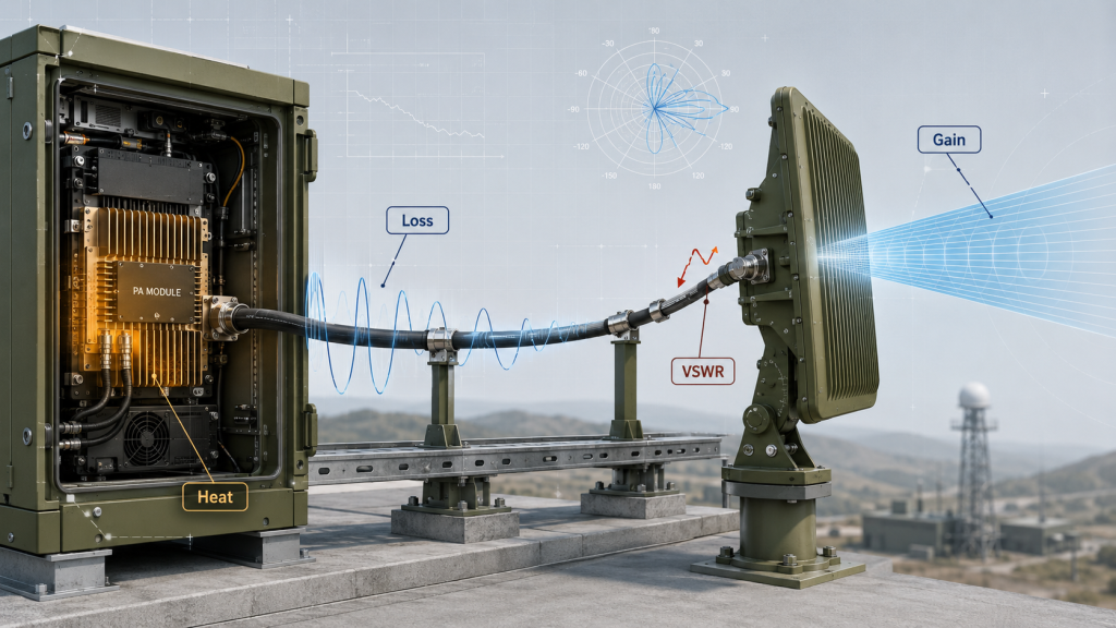
Loss, gain, mismatch, and heat must be checked together because C-UAS System EIRP is the combined result of PA output, feeder loss, connector loss, antenna gain, mismatch behavior, thermal derating, and operating conditions. If one part is ignored, the EIRP result may look better on paper than it will in the field.
The better check is simple: start from PA output, then subtract real losses, add real antenna gain, and adjust for the operating state.
Which Variables Change the EIRP Result?
A useful EIRP review should include both RF-chain components and PA operating conditions. This avoids approving a number that only works in a clean lab condition.
Check these variables:
- PA output at the defined boundary
- Feeder cable type and length
- Connector, adapter, and lightning protector loss
- Switch, filter, combiner, or splitter loss
- Antenna gain and gain unit
- Antenna pattern and direction
- Antenna mismatch and reflected power
- Thermal derating under outdoor operation
- Voltage and current behavior
- Continuous or burst output condition
EIRP should also consider RF Power Amplifier antenna mismatch because reflected power can reduce delivered antenna-port output before antenna gain is applied.
Why Do Frequency and Heat Matter?
Frequency-specific EIRP matters because RF output drops at high-frequency bands and feeder loss may reduce antenna-port power before antenna gain is applied. For outdoor border cabinets, EIRP should also be calculated from derated output when heat changes the PA’s sustained power.
Key Takeaway: EIRP should be calculated from the real operating chain, not from ideal PA output and ideal antenna gain.
| Variable | Effect on EIRP | Common Risk |
|---|---|---|
| Feeder loss | Lowers antenna input power | Underestimated cable loss |
| Antenna gain | Raises directional EIRP | Pattern ignored |
| Mismatch | Reduces delivered power | VSWR not checked |
| Heat | Lowers sustained PA output | Lab output used in field |
| Frequency | Changes loss and gain | One point used for all bands |
This table helps engineers prevent paper EIRP from becoming field disappointment.
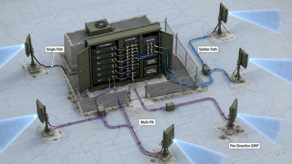
7. How Do Single-PA, Multi-PA, and Multi-Antenna Designs Change EIRP?
Single-PA, multi-PA, and multi-antenna designs change C-UAS System EIRP because each RF path has its own loss, antenna gain, direction, and operating condition. Total PA wattage cannot be directly added and treated as one system EIRP value.
The selection risk appears here: a system with several PA modules may look powerful in a bill of materials, but each antenna direction still needs its own EIRP review.
What Does Each Architecture Change?
Different RF architectures create different loss and direction behavior. Each should be reviewed as a path, not only as a total wattage count.
Common architectures include:
- Single PA + single antenna
- Single PA + splitter + multiple antennas
- Multiple PAs + multiple antennas
- PA + switch + antenna paths
- Combiner or filter path
- Sector antenna layout
In a splitter architecture, each antenna path receives only part of the PA output and adds splitter loss. In a multi-PA architecture, each path may need its own per-channel and per-direction EIRP.
Why Can’t You Add All PA Watts Together?
PA watts belong to modules. EIRP belongs to a defined antenna direction. If multiple antennas point in different directions or work through different RF paths, adding their PA wattage does not describe one real radiated direction.
Key Takeaway: EIRP should be calculated per RF path, per frequency, and per antenna direction.
| Architecture | EIRP Question | Main Risk |
|---|---|---|
| Single PA + antenna | What is the path loss and gain? | Simple but still boundary-dependent |
| PA + splitter | How much reaches each antenna? | Splitter loss ignored |
| Multi-PA system | What is each channel EIRP? | Total watts overestimated |
| Switch path | Which path is active? | Wrong path loss used |
| Sector antennas | What is each direction EIRP? | Pattern not reviewed |
This table prevents teams from confusing total module wattage with direction-specific system EIRP.
8. What Evidence Proves C-UAS System EIRP
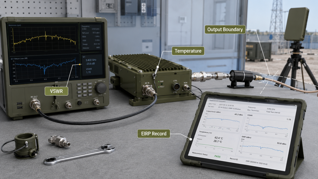
Test evidence should verify PA output and C-UAS System EIRP by recording output power, RF path loss, antenna gain, antenna direction, VSWR, temperature, voltage, operating mode, and measurement boundary. A PA output screenshot alone cannot prove the installed system EIRP.
Here’s the practical risk: if EIRP is lower than expected, the cause may be PA output, feeder loss, antenna mismatch, thermal derating, voltage drop, incorrect gain units, or wrong measurement boundary. Without evidence, teams can only guess.
What Should an EIRP Evidence File Include?
A useful file does not need to become a certification document, but it should contain enough data to support engineering review and customer retesting.
Include:
- Module serial number
- PA output by frequency point
- Measurement boundary
- Feeder type and length
- Connector, adapter, and lightning protector list
- Estimated or measured RF path loss
- Antenna gain and unit
- Antenna direction or sector
- VSWR and reflected power
- Voltage, current, and temperature
- Continuous or burst output condition
- EIRP calculation sheet or acceptance note
For outdoor cabinets, RF Power Amplifier derated output should be used when heat changes sustained PA output. Multi-site projects should also review RF Power Amplifier output tolerance, because batch variation can create EIRP differences between border or coastline stations.
Why Does Protection Feedback Help?
VSWR, temperature, and voltage protection help engineers explain whether an EIRP change comes from PA behavior, RF path mismatch, thermal condition, supply condition, or antenna load.
Key Takeaway: EIRP evidence should connect the PA module, RF path, antenna, and operating condition into one repeatable record.
| Weak Evidence | Better Evidence | Why It Matters |
|---|---|---|
| PA output screenshot | Output plus boundary | Defines starting point |
| Antenna gain only | Gain plus pattern | Shows direction |
| No path loss | Full loss list | Avoids inflated EIRP |
| No thermal state | Derated output record | Matches field condition |
| No S/N data | Unit-level report | Supports traceability |
This table helps procurement and engineering teams request evidence that supports real EIRP judgment.
9. What EIRP Information Should Buyers Share Before Quotation?
Before quotation, buyers should define target bands, PA output, RF path loss, antenna gain, antenna direction, measurement boundary, EIRP target, EIRP limit, and whether C-UAS System EIRP must be verified after installation. Asking only for “200W PA modules” is not enough for border or coastline projects.
This is where RFQ quality decides how accurate the supplier proposal can be. If the buyer does not define the EIRP target or boundary, the supplier can only quote PA modules, not system-level RF behavior.

What Should Enter the RFQ?
The RFQ should help both sides build the same EIRP assumption. It does not need perfect final drawings at the first stage, but it should define the main system variables.
Share or request:
- Target frequency bands
- Required PA output by band
- Target EIRP, if defined
- EIRP upper limit or project boundary
- PA-port, cabinet, feeder-end, or antenna-input boundary
- Antenna type and gain
- Gain unit: dBi or dBd
- Antenna pattern and direction
- Feeder type and length
- Connector, adapter, and lightning protector count
- Combiner, splitter, switch, or filter path
- Outdoor temperature and duty condition
- Need for field verification or EIRP evidence
If the project does not define these items, the quotation may match module power but miss the system EIRP requirement.
Why Should EIRP Limits Be Discussed Early?
EIRP is not only a performance number. It may also be subject to project-defined or authorized boundaries, so the design must control both minimum required EIRP and maximum allowed EIRP.
Key Takeaway: A strong RFQ defines the EIRP target and the installed RF-chain assumptions before module selection becomes final.
| RFQ Item | Why It Matters | Risk If Missing |
|---|---|---|
| EIRP target | Defines system goal | PA watts replace system metric |
| RF path loss | Changes antenna input power | EIRP is overestimated |
| Antenna gain | Adds directional effect | Wrong radiated result |
| EIRP limit | Controls boundary | Overdesign or compliance risk |
| Field verification | Confirms installed result | Paper-only approval |
This table helps buyers turn EIRP from a formula into a quotation and acceptance requirement.
10. How to Judge C-UAS System EIRP Before Approval
RF PA output supports the required C-UAS System EIRP only when the installed system can deliver the needed antenna-direction power after RF path loss, antenna gain, mismatch, thermal derating, operating mode, and project-defined EIRP limits are included. The decision should start from the system requirement, not from the module watt label.
This is the final engineering path: calculate, verify, and document the installed RF chain before treating PA output as enough.
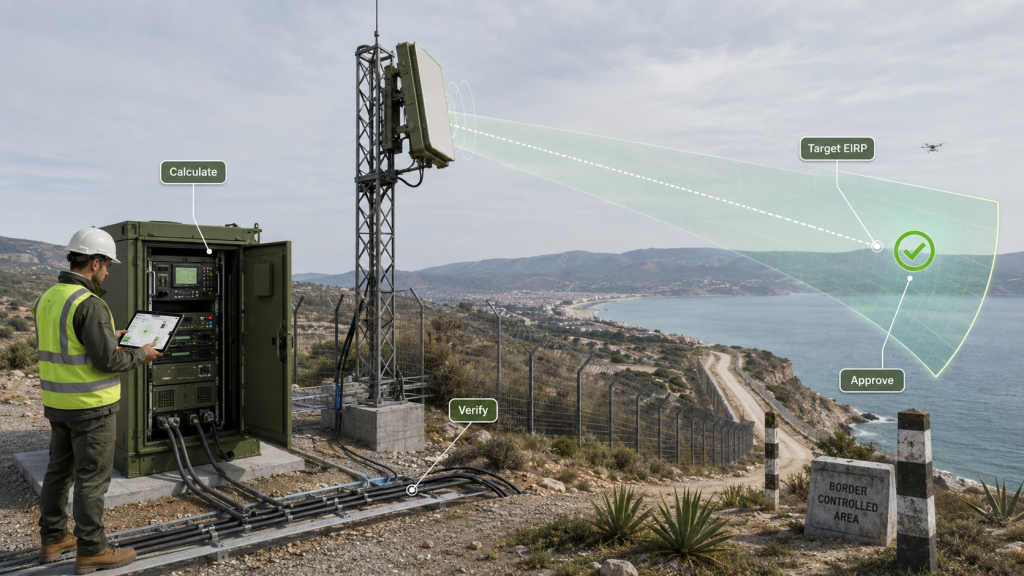
What Decision Sequence Should Engineers Use?
Use a structured decision sequence before final approval:
- Define the target frequency and direction.
- Confirm whether the requirement is PA output or EIRP.
- Define the measurement boundary.
- Confirm PA output under the required voltage, duty, and temperature.
- Subtract feeder, connector, adapter, and hardware loss.
- Add antenna gain in the correct unit.
- Review antenna pattern and direction.
- Check mismatch, VSWR, and reflected power.
- Use derated output when heat matters.
- Compare the result with EIRP target and limit.
As an RF Power Amplifier module and C-UAS core component source factory, RF SKYPOWER can support border and coastline projects by reviewing PA output, feeder-chain loss, antenna gain, antenna direction, VSWR feedback, derated output, batch consistency, and repeatable EIRP evidence before final approval.
When Should the Design Be Reworked?
The design should be reworked when RF path loss is too high, antenna gain does not match the target direction, thermal derating reduces the PA output, mismatch changes antenna-port power, or the calculated EIRP falls outside project limits.
If your border or coastline C-UAS project has not confirmed PA output, RF path loss, antenna gain, antenna direction, VSWR, derated output, and EIRP target, you can review your C-UAS system EIRP requirement with a source-factory engineering team before final approval.
Key Takeaway: PA output supports EIRP only when the installed RF path and antenna system preserve the required directional result.
| If the Result Shows… | Start With… | Recommended Action |
|---|---|---|
| High PA output, low EIRP | RF path loss | Shorten or improve path |
| Good antenna gain, weak result | Feeder and mismatch | Check antenna input power |
| EIRP too high | Antenna direction or gain | Rebalance design |
| Hot-state EIRP drops | PA derating | Review cooling and duty |
| Different sites vary | Batch and installation data | Compare S/N and path records |
This table gives engineering and procurement teams a final review path before project approval.
FAQ
Is RF PA output power the same as EIRP?
No. RF PA output power is the power at a defined module or cabinet boundary, while EIRP includes RF path loss and antenna gain in a defined direction.
What is the basic formula for C-UAS system EIRP?
A practical formula is EIRP (dBm) = PA Output (dBm) − RF Path Loss (dB) + Antenna Gain (dBi). The inputs must match the installed system boundary.
Can a 200W PA produce lower EIRP than expected?
Yes. Long feeder cables, connector loss, mismatch, switching hardware, heat derating, or low antenna gain can reduce the final system EIRP.
Should EIRP be calculated per channel or for the whole system?
Calculate EIRP per frequency, per RF path, and per antenna direction. Do not use total module wattage as one system EIRP number.
What should I check before quoting a C-UAS EIRP requirement?
Check target bands, PA output, RF path loss, antenna gain, antenna direction, measurement boundary, mismatch, derated output, EIRP limits, and verification evidence.
Conclusion
RF PA output power and C-UAS system EIRP are connected, but they are not the same metric. PA output is the starting point. System EIRP depends on how much of that power remains after feeder cables, connectors, adapters, lightning protection, switches, filters, mismatch, and other RF path losses, and how the antenna gain and direction shape the final radiated power.
For system integrators, RF engineers, and procurement reviewers, the practical lesson is clear: do not approve a border or coastline C-UAS system only by single-module PA wattage. Define the measurement boundary, calculate RF path loss, confirm antenna gain and pattern, check VSWR, use derated output when heat matters, compare per-frequency and per-direction EIRP, and keep repeatable test evidence for project approval.
RF SKYPOWER supports system EIRP evaluation by reviewing PA output, feeder-chain loss, antenna gain, antenna direction, VSWR feedback, derated output, batch consistency, and repeatable test reports before final project delivery. If your team needs to align RF PA output, EIRP targets, antenna direction, RF path loss, and project-defined limits before module selection, you can discuss your project with RF SKYPOWER before the system architecture is locked.
Reliable border and coastline C-UAS integration starts with verified system EIRP, not a single-module watt label.