










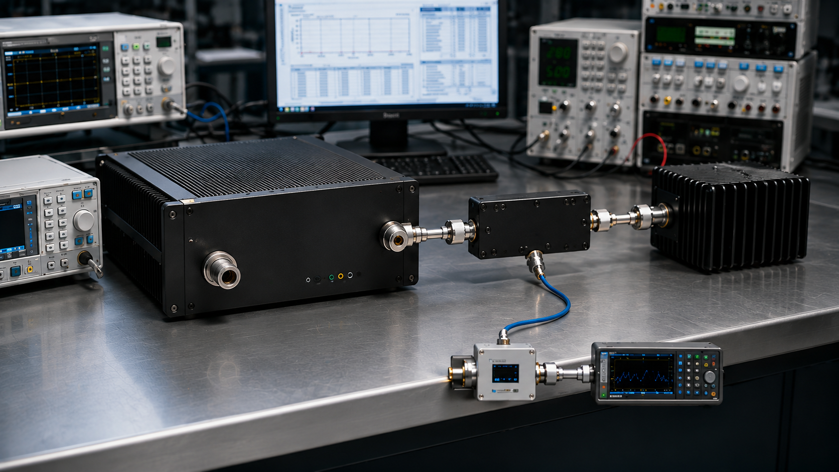
A shipment report can show the required RF output power verification result and still leave the buyer unable to approve the module. The displayed wattage may represent a valid reading at one measurement point without proving the Pout required at the acceptance reference plane.
That gap matters before shipment because two reports can show the same wattage while supporting different acceptance conclusions. A buyer therefore needs to know what the reported Pout actually represents before treating the number as release evidence.
So before accepting shipment Pout, what must the evidence show to prove that the number belongs to the right hardware, under the right test boundary, at the right measurement reference plane?
1. What a Shipment Pout Number Must Define
A reported RF output value is not complete until the buyer knows what quantity was measured and under which operating condition.
Before accepting Pout, define both the signal or waveform condition and the reported power metric.
The signal condition may be:
- CW;
- a specified modulated waveform;
- a defined pulsed condition;
- or another agreed RF condition.
The reported power metric may be:
- average RF power;
- peak RF power;
- peak-envelope power where applicable;
- or another explicitly defined metric.
CW describes a signal or operating condition rather than a power metric. Average, peak, and peak-envelope power where applicable should therefore be interpreted together with the stated waveform condition.
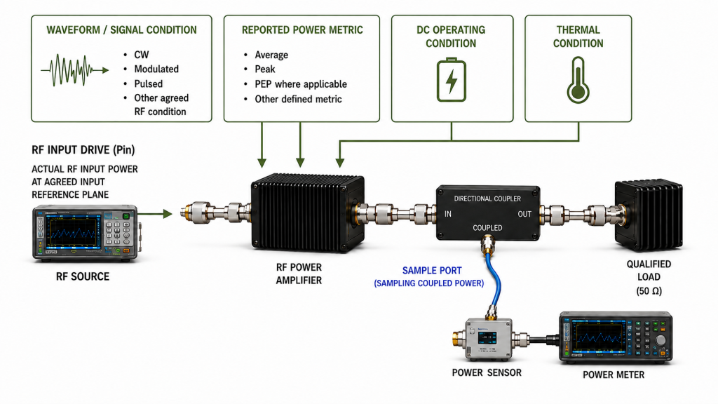
The shipment record should also identify the operating conditions that materially affect the result, such as:
- frequency;
- actual RF input power (Pin);
- load condition;
- Vdc and relevant Idc boundary;
- duty cycle;
- test duration;
- thermal state;
- cooling condition;
- protection state where applicable.
The purpose is not to force every shipment test into the same template.
The purpose is to make the reported Pout interpretable against the actual acceptance requirement.
2. How to Build a Reviewable Shipment Pout Record
A reviewable shipment result should let another engineer understand what was physically measured and how the final reported Pout was established.

Start with the raw measurement point
The report should first identify where the RF power sensor, coupler, meter, or other measurement device actually observed the signal.
That physical measurement point is not automatically the final Pout reference plane.
If the sensor is downstream from the PA output connector, the report should distinguish:
- Raw measured power — the value observed at the physical measurement point;
- Applied path / fixture correction — the documented treatment for relevant cable, attenuator, coupler, adapter, fixture, or other characterized transfer effects;
- Corrected Pout — the value represented at the declared final reference plane.
The report should not use raw measured power and corrected Pout as if they were the same quantity.
Keep instrument calibration separate from path correction
Instrument or sensor calibration is not simply another RF-path loss term.
The measurement record should separately identify the equipment and applicable power meter and sensor calibration status needed to establish that the measurement chain was valid for the test.
This may include, where required:
- power meter or sensor identity;
- coupler identity;
- applicable calibration status;
- calibration validity period;
- measurement configuration;
- or other project-defined traceability information.
A calibration record supports confidence in the measurement system.
A path or fixture correction explains how a value measured at one physical point is represented at another declared reference plane.
These are different functions and should not be merged into one correction number.
Declare the Pout reference plane
PA-port Pout is the output value represented at the declared PA-output reference plane.
If the sensor is physically located downstream, the report should state:
- the raw measurement point;
- the declared PA-output reference plane;
- which path or fixture corrections lie between them;
- and how the final corrected Pout was obtained.
For a deeper review of this boundary, see test cable loss compensation.
Record actual Pin
A Pout result should not be reviewed independently of actual Pin when input drive materially affects the operating point.
Record the actual RF input power at the agreed input reference plane rather than assuming that every output result was produced with the same drive.
This is especially important when comparing:
- two frequency points;
- two modules;
- cold-state and hot-state results;
- or supplier reports generated under different input conditions.
Separate stabilized hot-state from a fixed dwell result
Do not label a result hot-state only because the module has been operating for a specified amount of time.
A stabilized hot-state Pout result should be recorded only after the agreed thermal stabilization criterion has been met under the stated:
- RF operating condition;
- DC condition;
- load;
- duty cycle;
- cooling method;
- and relevant ambient or thermal boundary.
If the acceptance plan specifies only a fixed dwell time without confirming thermal stabilization, report the result as a time-based dwell measurement rather than automatically labeling it stabilized hot-state evidence.
A fixed-duration result can still be a valid acceptance condition. It simply proves a different boundary.
Use FWD / REV only when they belong to the test plan
FWD, REV, return loss, or VSWR can help interpret the load condition when they are part of the agreed shipment evidence.
Where they are required, record the applicable:
- reference plane;
- measurement method;
- operating condition;
- timing;
- sensor or coupler location;
- calibration status where relevant;
- and detector or averaging method where relevant.
These values support interpretation of the load state.
They should not replace the primary Pout measurement or be treated as universally required for every shipment plan.
Keep Vdc and Idc inside the agreed operating boundary
Instead of asking whether current “increased normally,” verify whether Vdc and Idc remained within the agreed operating boundary during the RF output measurement.
The acceptance question is whether the delivered unit produced the required Pout under the specified electrical condition—not whether every PA follows one generic current trend.
3. Keep Shipment Pout at the Declared Reference Plane
A factory shipment result should prove the measurement boundary that was actually defined.
It should not automatically be expanded into a downstream or antenna-side power claim.
A factory PA-port result proves only the declared PA-port measurement boundary. Installed downstream power requires a separate RF-path, measurement-quantity, and reference-plane definition.
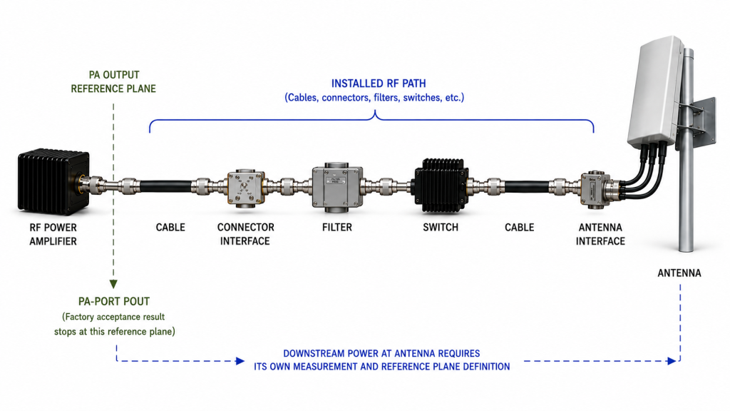
For example, an antenna-side requirement might refer to:
- forward power at the antenna input;
- net accepted power at a stated plane;
- corrected forward power after an installed RF path;
- or another explicitly defined system metric.
Those quantities are not automatically equivalent to factory PA-port Pout.
Likewise, a scalar path-loss value characterized under one condition should not be assumed to convert PA-port Pout into a valid downstream quantity under every installed load condition.
This page therefore treats shipment Pout verification as a factory acceptance problem at a declared reference plane. Installed-system power should be verified under its own RF-path and load boundary.
4. What Makes Shipment Pout Evidence Reviewable
A strong shipment record does not need unnecessary screenshots. It needs enough information to reconstruct what the reported Pout actually represents.
| Report Item | What Must Be Defined | What the Evidence Can Support | Common Acceptance Risk |
|---|---|---|---|
| Reported Pout | Signal / waveform condition and reported power metric | Which RF quantity is being reported | Average, peak, PEP, and waveform context treated as equivalent |
| Raw measurement point | Physical sensor or measurement location | Where the instrument actually observed RF power | Raw reading mistaken for PA-port Pout |
| Declared reference plane | Final Pout plane used for acceptance | What corrected Pout represents | Results from different planes compared directly |
| Path / fixture correction | Included cable, attenuator, coupler, adapter, fixture, or other characterized transfer terms | How the raw measurement is translated to Pout at the declared reference plane | Missing, duplicated, wrong-sign, or undocumented correction |
| Instrument / sensor calibration | Measurement-equipment identity and applicable calibration status | Whether the measurement chain was valid for the required test | Path correction confused with instrument calibration |
| Actual Pin | Input power and input reference plane | RF input condition behind the Pout result | Different drive levels treated as comparable |
| Frequency | Required acceptance point or sweep | Where the result applies | One favorable point treated as full-band proof |
| Thermal / duration condition | Stabilization criterion or explicitly defined dwell condition, cooling, duty cycle | Whether the result is stabilized hot-state, transitional, or time-based | Fixed dwell result mislabeled as stabilized hot-state |
| DC condition | Project-defined Vdc and relevant Idc boundary | Electrical operating state during the measurement | Pout compared under different supply conditions |
| Load condition | Qualified test load and applicable boundary | RF load state behind the result | Different load conditions treated as equivalent |
| Unit identity / evidence scope | Delivered S/N when unit-level evidence is required, or the actual batch / configuration / qualification scope | Which hardware the evidence legitimately applies to | Sample or batch evidence treated as delivered-unit proof |
Evidence scope matters
Not every acceptance record has to operate at the same evidence level.
A project may define:
- unit-level evidence;
- batch-level evidence;
- configuration-level evidence;
- qualification evidence;
- or another agreed acceptance structure.
These scopes should not be mixed.
When the agreed shipment plan requires unit-level RF output evidence, the Pout dataset and applicable test conditions should remain linked to the delivered module S/N.
In that case, a clear traceability chain is appropriate:
One Unit → One Serial Number → One Pout Dataset → One Test Report → Traceable Acceptance Evidence
When a result belongs to a broader batch, configuration, or qualification scope, it should remain identified according to that actual scope rather than being presented as per-unit proof.
For the wider shipment-release structure beyond Pout alone, see the C-UAS RF PA acceptance checklist.
Full-band evidence is a separate test-method question
If shipment approval requires multiple frequency points or a full-band power sweep, the report should state that requirement explicitly.
A single-frequency result should not silently become proof of full-band compliance.
The detailed test method belongs in the swept-frequency full-power RF PA test rather than being compressed into one shipment Pout value.
5. How to Define RF Output Verification in the RFQ
The RFQ should not ask only:
“Please provide your RF output power before shipment.”
That request does not define what the number must represent.
Instead, specify the acceptance boundary before the test is performed.
RFQ Checklist
| RFQ Item | Customer Input Needed |
|---|---|
| Frequency requirement | Required band and acceptance frequency points |
| Signal / waveform condition | CW or specified modulated / pulsed waveform and relevant parameters |
| Reported power metric | Average, peak, PEP where applicable, or another agreed metric |
| Target Pout | Required RF output under the stated operating condition |
| Pout reference plane | Declared PA-output or other agreed acceptance reference plane |
| RF input condition | Required Pin, drive level, and input reference plane |
| Load condition | Qualified test load and applicable mismatch boundary where required |
| DC condition | Project-defined Vdc and relevant Idc operating boundary |
| Duty cycle | CW or specified duty cycle |
| Thermal state / dwell condition | Stabilization criterion when hot-state evidence is required, or explicitly defined fixed-duration condition |
| Cooling condition | Cooling method and relevant thermal / ambient boundary |
| Raw measurement point | Physical sensor, coupler, or measurement location |
| Path / fixture correction method | Required treatment for cable, attenuator, coupler, fixture, adapter, or other characterized transfer effects |
| Instrument / sensor identity | Required measurement-equipment identification where applicable |
| Calibration status | Required calibration validity or traceability boundary |
| FWD / REV evidence | Required only where it belongs to the agreed test plan |
| Acceptance limit | Pass / fail threshold at the declared reference plane |
| Evidence scope | Unit, batch, configuration, qualification, or other agreed scope |
| S/N linkage | Required when unit-level output evidence is part of acceptance |
| Quantity | Units covered by the acceptance plan |
The RFQ does not need every row for every project.
Only define the conditions that materially affect whether the reported Pout can be accepted.
FAQ
Is one RF output power screenshot enough for shipment approval?
A screenshot alone does not establish the full acceptance boundary unless the required measurement and test context is available elsewhere in the approved record.
The buyer still needs to know what power metric is shown, where it was measured, which reference plane the reported Pout represents, what path or fixture correction was applied, and under which frequency, Pin, load, DC, duration, and thermal conditions the result was obtained.
A screenshot can be part of the evidence, but it should not replace the defined test context.
What is the difference between raw measured power and corrected PA-port Pout?
Raw measured power is the value observed at the actual physical measurement point.
Corrected PA-port Pout is the value represented at the declared PA-output reference plane after the applicable path or fixture correction has been applied.
Instrument calibration establishes a different part of the evidence chain: whether the measurement system used for that reading was valid for the required test.
Does every delivered RF PA need its own Pout report?
Only when the agreed acceptance structure requires unit-level evidence.
If unit-level RF output acceptance is required, the Pout dataset should remain linked to the delivered S/N.
If the project instead uses batch-level, configuration-level, or qualification evidence for a particular test, that evidence should be labeled according to its actual scope rather than presented as per-unit proof.
Conclusion
An RF output number is suitable for C-UAS shipment acceptance only when the buyer can determine what power quantity was reported, under which operating condition, where it was measured, which reference plane the final Pout represents, how path or fixture correction was applied, whether the measurement system was valid for the test, and what hardware or evidence scope the result legitimately covers.
A raw instrument reading is not automatically corrected PA-port Pout. Instrument calibration is not the same as RF-path correction. A fixed dwell-time measurement is not automatically stabilized hot-state evidence, and a generic sample record should not be presented as delivered-unit proof when unit-level acceptance is required.
Once the shipment Pout boundary is defined, a custom RF power amplifier module can be reviewed against the required frequency points, output target, Pin, load, DC and thermal boundary, measurement reference plane, and acceptance evidence.
For shipment-acceptance review, provide the required frequency points, signal or waveform condition, reported power metric, target Pout and reference plane, Pin, load, project-defined Vdc / Idc boundary, duty cycle, thermal stabilization or dwell requirement, path / fixture correction method, calibration requirement, quantity, evidence scope, and required S/N-linked report format where unit-level evidence applies.