










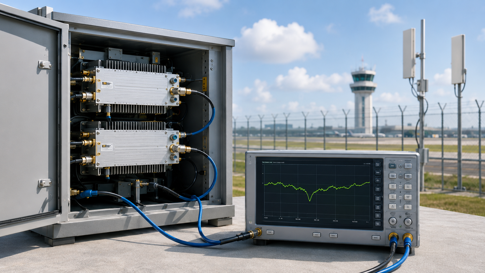
RF PA gain ripple may appear as a small local dip inside an otherwise acceptable frequency curve. That dip does not automatically mean the module has failed, but it may identify a frequency that needs closer review.
For RF Power Amplifier Modules, engineers should not approve or reject a suspected dip from curve shape alone. They must first define the PA reference planes, test method, operating conditions, and project acceptance limits.
A weak frequency point is a frequency that shows less output margin, requires more input drive, reaches an electrical or thermal limit sooner, or approaches a protection boundary more closely than surrounding points. It does not automatically mean the RF PA is unacceptable.
A reliable review must answer three questions:
- Is the local dip real and repeatable?
- Does it reduce usable output or operating margin?
- Does the cause belong to the PA, the test setup, or the installed RF path?
1. What RF PA Gain Ripple Is—and What It Is Not
For this engineering review, gain flatness describes the broader gain variation across a specified frequency range. Gain ripple refers to smaller local peaks or dips within that curve.
A module may meet its overall gain-flatness requirement while still showing a local dip at one critical frequency. The opposite is also possible: a curve may look uneven, but every required operating point may still meet the defined output, drive, thermal, and protection limits.
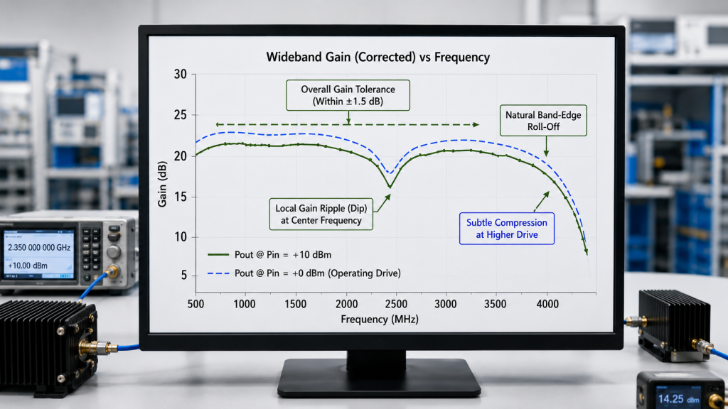
Gain ripple should also be separated from band-edge drop and gain compression.
| Term | What It Describes | What It Does Not Prove | Required Next Check |
|---|---|---|---|
| Gain flatness | Broad gain variation across a defined range | Whether one local frequency fails the project requirement | Mark the required operating points |
| Gain ripple | A local peak or dip inside the range | Whether the point fails under the required operating condition | Repeat the point with defined Pin and reference planes |
| Band-edge drop | Reduced performance near the lower or upper frequency limit | Whether a mid-band dip is acceptable | Verify the required edge frequencies |
| Gain compression | Gain reduction as the PA approaches higher output | Small-signal frequency response | Compare low-drive and operating-drive results |
A visible dip is therefore a test trigger, not an automatic rejection condition.
The broader RF PA gain-flatness check should establish the frequency range, input condition, load, temperature state, and required tolerance. Gain-ripple analysis then focuses on specific frequencies that show less margin than nearby points.
2. How to Identify a Project-Critical Ripple Dip
Begin with the project frequency plan, not with the appearance of the supplier’s curve.
Mark:
- the required operating range;
- exact priority frequencies;
- low, center, and high review points;
- required band-edge frequencies;
- points with strict minimum output limits;
- and frequencies included in acceptance testing.
A dip at an unused frequency may have little project impact. A smaller dip at a required operating point may need full-power and hot-state confirmation.
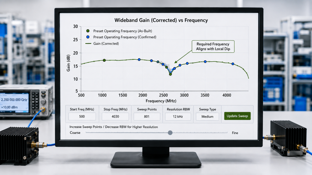
Use Enough Frequency Resolution
A low-center-high test can miss a local dip between the selected points.
The report should identify:
- the sweep step size;
- the complete frequency-point list;
- or the project frequencies added to the standard sweep.
The objective is not to demand the smallest possible interval. The frequency resolution must be fine enough to avoid skipping the points that matter to the project.
Add Local Confirmation Points
When a full-band sweep reveals a suspected dip, add more points around it.
Include:
- the suspected minimum;
- one or more points below it;
- one or more points above it;
- and a nearby reference point with normal behavior.
This local sweep helps determine whether the dip is repeatable, narrow, broad, thermally sensitive, or caused by normal measurement variation.
Keep the Comparison Boundary Consistent
Use the same:
- PA input reference plane;
- PA output reference plane;
- test method;
- load condition;
- DC condition;
- cooling condition;
- and thermal state.
Actual Pin should also remain within a defined tolerance at the PA input reference plane. A small Pin variation can distort the comparison when the suspected ripple is itself small.
3. When a Gain Dip Becomes an Acceptance Risk
A local dip becomes an acceptance concern only when it affects one or more project-defined limits.
These limits may include:
- minimum corrected Pout;
- maximum available Pin;
- specified gain or ripple tolerance;
- required output margin;
- PA-terminal voltage;
- operating current;
- temperature limit;
- VSWR or reflected-power boundary;
- protection behavior;
- or hot-state stability.
Corrected Pout is important, but it is not the only acceptance condition.
A frequency may reach the target output while requiring more input drive than the SDR or driver can supply. Another point may meet Pout but exceed an agreed current or thermal limit. A third may pass during a short cold test and lose margin after heat builds.
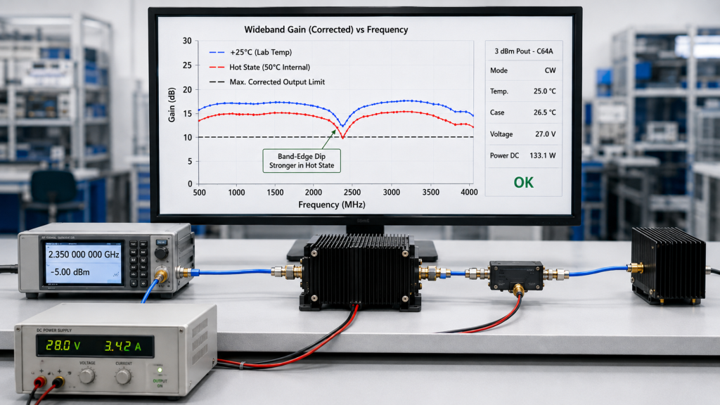
Use a Defined Test Sequence
A practical review can use three stages.
First, screen the full range.
Use a small-signal or agreed low-drive fixed-Pin sweep to locate local dips. Add more frequency points around any suspected minimum.
Second, confirm the point at the agreed operating drive.
Repeat the suspected dip and nearby points with actual Pin held within a defined tolerance. Record corrected Pout and large-signal gain.
Third, check drive margin where required.
Use an adjusted-Pin test to determine whether the point can reach the target output and how much input drive it requires.
These stages answer different questions and should not be treated as interchangeable results.
Fixed-Pin Tests Must Identify the Operating Level
A fixed-Pin sweep holds actual Pin at the PA input reference plane within a defined tolerance at each frequency.
It answers:
How do gain and output vary across frequency under the same input condition?
However, a fixed-Pin sweep may be performed at either:
- a small-signal level;
- or the agreed operating drive.
The report must identify the actual Pin and state whether the curve represents small-signal gain or large-signal behavior. A small-signal ripple curve cannot by itself prove full-power output margin.
Adjusted-Pin Tests Measure Output and Drive Margin
An adjusted-Pin test changes Pin at each frequency until the PA reaches the target Pout or the available input limit.
It answers:
Can this frequency reach the target output, and how much input drive does it require?
This method is useful when the project must confirm both output capability and the available SDR or driver margin.
Fixed-Pin and adjusted-Pin results may appear in the same report, but they must be labeled and interpreted separately.
Record Pin and Pout at Matching Reference Planes
Measure or verify actual Pin at the PA input reference plane.
A lower Pin can reduce Pout, but it does not necessarily reduce calculated gain. Calculate large-signal gain only from actual Pin and corrected Pout measured at matching reference planes.
Correct the measured output back to the defined PA output reference plane. The correction record should identify:
- directional-coupler coupling factor;
- sample-path cable loss;
- attenuator value;
- sensor or meter correction;
- and any loss between the PA connector and the selected reference plane.
Do not combine mainline insertion loss and sample-path correction without showing the calculation direction.
Repeat the Dip After Thermal Stabilization
A cold-state pass does not prove hot-state margin.
Repeat the suspected frequency and nearby comparison points after the defined operating period. Record:
- actual Pin;
- corrected Pout;
- PA-terminal Vdc;
- operating current;
- temperature value and measurement location;
- cooling condition;
- operating duration;
- stabilization rule;
- reflected-power or VSWR status;
- and protection state.
A swept-frequency full-power RF PA test provides the wider test structure. The gain-ripple review should extract the specific points and measurements needed to judge the local dip.
4. How to Separate PA Ripple from Test and RF-Path Effects
A weak result at one frequency does not automatically prove intrinsic PA gain ripple.
The source path, DC supply, temperature, load, protection system, or installed RF chain may create or deepen the apparent dip.
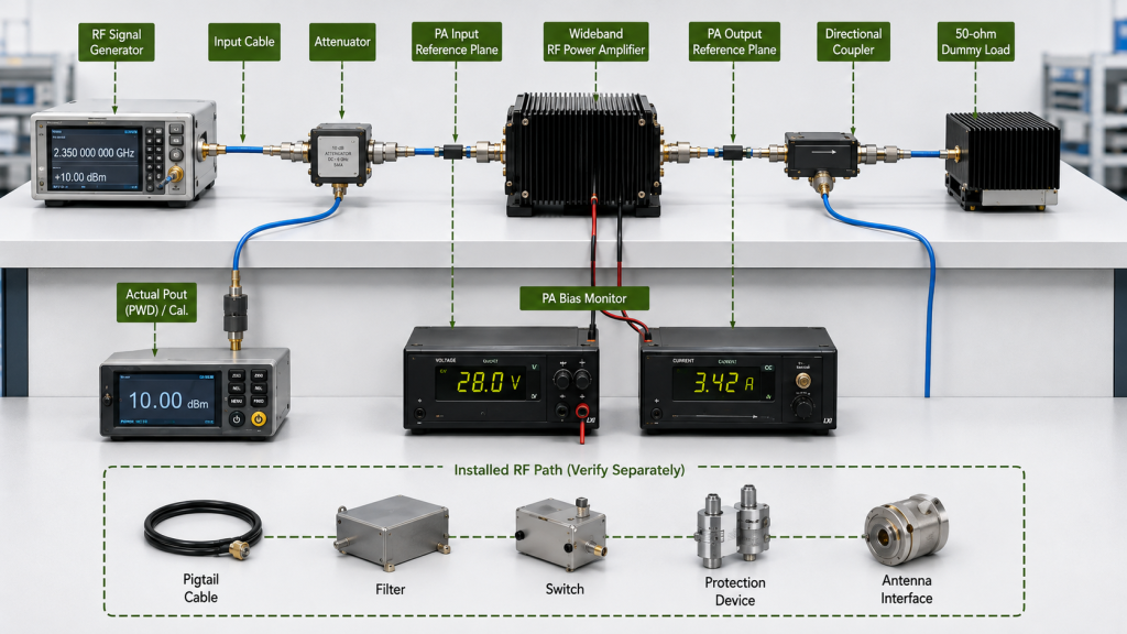
Verify the Input Path
A constant signal-generator setting does not guarantee constant Pin at the PA connector.
Frequency-dependent loss may come from the source, driver, input cable, connector, adapter, switch, or filter.
Measure or verify actual Pin at the PA input reference plane. If Pin falls at the same frequency as Pout, the source path may be contributing to the apparent weakness.
Measure DC Conditions at the PA Terminal
The power-supply setting is not always the voltage available at the PA during operation.
Cable resistance, connector resistance, current demand, and supply margin can reduce PA-terminal voltage. Record Vdc and Idc while the module is operating.
A frequency that draws more current may show a larger voltage drop, higher temperature, or reduced output margin.
Establish the PA-Port Baseline First
Test the suspected dip at the PA output connector into:
- a specified 50 Ω dummy load;
- or another project-defined test load.
This establishes the PA-port baseline.
Then add the project feeder, connectors, filters, switches, protection devices, and antenna interface as a separate installed-path boundary.
The real antenna-path gain behavior should be reviewed after the PA-port baseline is clear. Otherwise, frequency-dependent path loss or antenna mismatch may be incorrectly assigned to the PA.
Connect Protection Status with the Measurements
Thermal rollback, current limiting, reflected-power protection, or another control response may reduce output at one frequency.
Connect the protection state with the same frequency, Pin, corrected Pout, PA-terminal voltage, current, temperature, load, and reflected-power records.
This helps distinguish intrinsic PA response from source-path variation, DC drop, thermal behavior, load sensitivity, protection action, or installed-path loss.
5. What Evidence Proves Whether a Ripple Dip Is Acceptable
The supplier does not need to prove a perfectly flat curve at every possible frequency.
The evidence must show whether the suspected dip satisfies all applicable project limits.
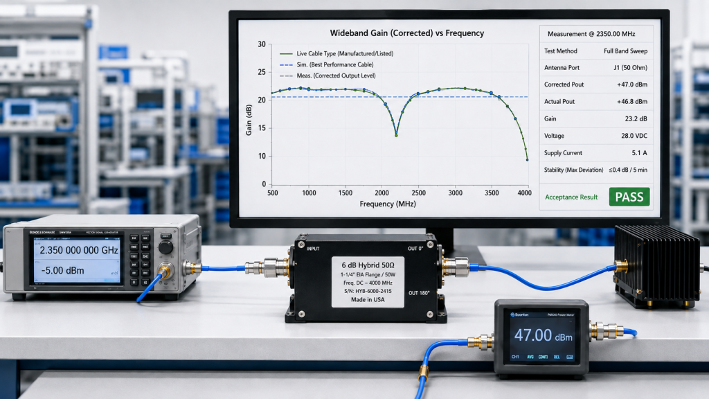
| Evidence Item | What Must Be Recorded | Why It Matters |
|---|---|---|
| Frequency | Exact suspected dip and nearby comparison points | Prevents approval from an average or center-frequency result |
| Test method | Small-signal fixed Pin, operating-drive fixed Pin, adjusted Pin, or a defined combination | Prevents different tests from being mixed |
| Actual Pin | Target, tolerance, and measured value at the PA input reference plane | Shows the real input and available drive margin |
| Corrected Pout | Result corrected to the defined PA output reference plane | Confirms usable module output |
| Large-signal gain | Calculated from matching Pin and Pout records | Shows behavior at the operating drive |
| Vdc and Idc | Values measured during operation | Reveals voltage drop and electrical load |
| Thermal state | Temperature value and location, stabilization rule, duration, and cooling condition | Shows whether the result remains valid after heat builds |
| Load and reflected status | Defined load plus VSWR or reflected-power condition | Separates PA response from load effects |
| Protection status | Normal, alarm, rollback, or limit state | Explains output changes linked to protection |
| Acceptance result | Pass, review, or fail against defined limits | Converts measurements into an approval decision |
| Unit identity | Model, S/N, revision, and report version | Links the evidence to the tested module |
Use One Connected Test Record
Do not combine a gain curve from one module with output, current, temperature, or protection data from another.
Each report should connect the relevant results through:
- the same module S/N;
- the same controlled configuration;
- defined input and output reference planes;
- the same frequency points;
- identified test equipment and corrections where required;
- test date;
- report number and version;
- and final release status.
Define Acceptance Before Judging the Dip
The acceptance boundary may include:
- minimum corrected Pout;
- maximum required Pin;
- specified gain-flatness or ripple tolerance;
- required hot-state margin;
- Vdc and Idc limits;
- temperature limit;
- VSWR or reflected-power boundary;
- and allowed protection behavior.
Do not invent a universal gain-ripple limit when the project has not defined one.
One visible dip may remain acceptable because every project limit still passes. A smaller dip may fail because it requires unavailable drive or loses margin after thermal stabilization.
RFQ Checklist for Suspected Gain-Ripple Dips
A statement such as “good gain flatness required” does not define how a local dip will be tested or accepted.
Before quotation, provide:
- required frequency range;
- exact priority frequencies;
- minimum corrected Pout;
- PA-port or antenna-end output reference;
- nominal test Pin at the PA input connector;
- maximum source or driver Pin available at that reference plane;
- required test method: small-signal fixed Pin, operating-drive fixed Pin, adjusted Pin, or a defined combination;
- available 28 V PA-terminal condition;
- operating duty;
- cooling and installation boundary;
- controlled-load or installed-path test requirement;
- expected VSWR or reflected-power limit;
- cold-state or hot-state test condition;
- sweep interval or required frequency-point list;
- required S/N-linked report format;
- and the pass, review, or fail limits.
The supplier should then confirm:
- the tested frequency points;
- the target Pin and allowed tolerance;
- how actual Pin will be measured;
- how measured output will be corrected;
- which test methods will be used;
- the load and cooling conditions;
- the operating duration and thermal stabilization rule;
- the recorded DC, reflected-power, and protection data;
- and whether the evidence represents a sample, a batch, or each delivered unit.
For projects that require several operating points inside one listed range, Wideband RF Power Amplifier Modules should be reviewed by target-frequency gain, corrected output, required Pin, hot-state behavior, and S/N-linked evidence rather than by frequency coverage alone.
A matching frequency label identifies a possible product route. It does not prove that every required frequency meets the project boundary.
Conclusion
RF PA gain ripple should not be accepted or rejected from curve shape alone.
First confirm that the suspected dip is repeatable at the required frequency. Then identify whether the result came from a small-signal fixed-Pin sweep, an operating-drive fixed-Pin test, or an adjusted-Pin test.
Establish the PA-port baseline before adding installed-path effects. Approve the point only when every applicable output, drive, electrical, thermal, load, and protection limit remains satisfied.
RF SKYPOWER can support early engineering review for suspected gain-ripple dips. Send the required frequency range, exact target points, minimum corrected Pout, nominal and maximum Pin at the PA input connector, available 28 V PA-terminal condition, duty cycle, cooling method, controlled-load or antenna-path boundary, VSWR limit, test method, and required S/N-linked report format.
The review can then determine whether the dip remains acceptable, requires additional full-power or hot-state evidence, or indicates that the quoted frequency block needs further engineering evaluation.