










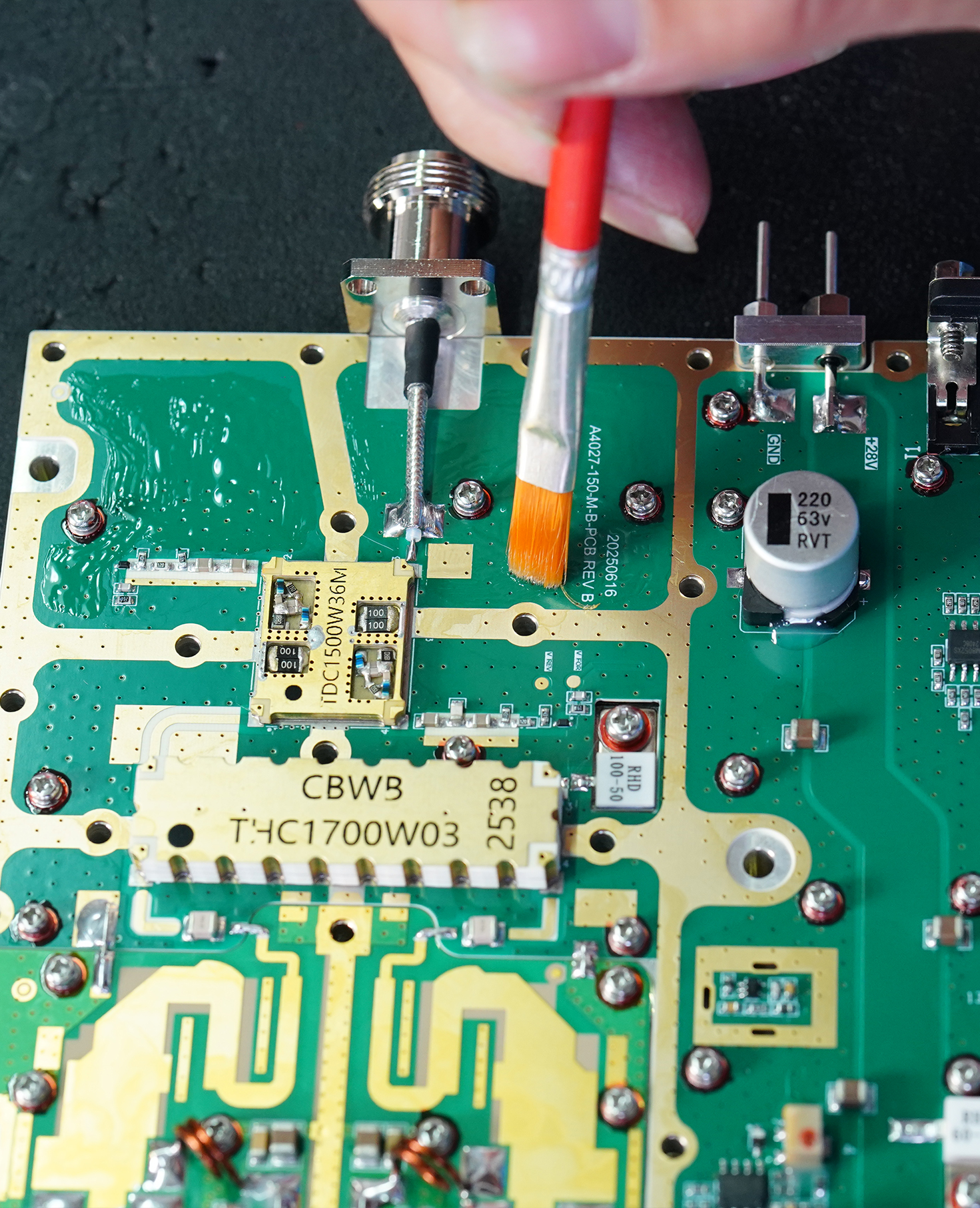
RF PA conformal coating adds a protective barrier over selected PCBA areas, helping reduce exposure to moisture, dust, oxidation, and airborne contamination. For RF power amplifier modules used in outdoor cabinets, mobile platforms, airports, border sites, and other demanding C-UAS installations, this process adds board-level environmental protection under changing operating conditions.
The value of conformal coating comes from more than the visible protective film. Reliable results depend on a controlled manufacturing chain that connects PCBA cleaning, surface preparation, selective application, curing, inspection, and post-coating RF verification.
The complete process can be summarized as:
Cleaning → Surface preparation → Selective coating → Curing → Inspection → Post-coating RF verification
Each stage supports the next. Cleaning prepares the PCBA surface. Selective application protects the required areas while keeping sensitive interfaces clear. Curing brings the coating to its specified process condition. Inspection confirms the finished film, and post-coating testing confirms that the completed RF PA assembly remains within its acceptance limits.
1. Why Conformal Coating Matters for RF PA Reliability
RF PA modules may operate in environments where humidity variation, dust, condensation risk, and airborne contamination are more demanding than conditions on a laboratory bench.
Over time, these environmental factors may affect exposed conductors, component surfaces, soldered areas, control circuits, and other parts of the PCBA.
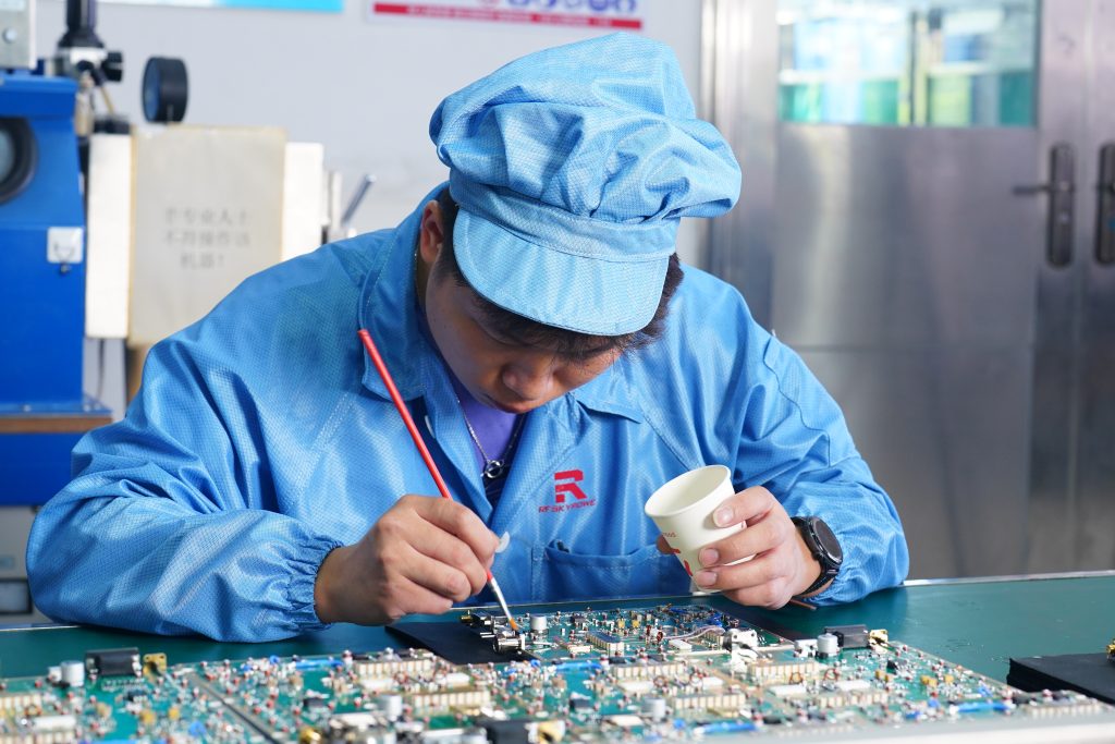
Conformal coating strengthens board-level environmental protection by forming a thin protective film over selected areas of the circuit board and mounted components. Depending on the approved material and application process, it can help reduce exposure to:
- Humidity and surface moisture
- Airborne dust and contamination
- Oxidation
- Corrosive airborne contaminants
- Moisture-related electrical leakage across exposed board surfaces
- Repeated environmental stress
This protection is especially useful in outdoor and semi-outdoor systems exposed to changing humidity, condensation risk, dust, and airborne contamination.
Because the film follows the shape of the board and components, it can protect selected PCBA surfaces that may be difficult to isolate through mechanical construction alone.
Within the complete RF PA system, board-level coating works together with the module enclosure, protected interfaces, cooling structure, cable-entry design, drainage, condensation control, and installation conditions.
These measures perform different but complementary functions:
- Conformal coating protects selected PCBA surfaces.
- The module structure protects the completed assembly.
- Connector and cable design protect external interfaces.
- Post-process testing confirms the finished module remains acceptable.
Together, these measures define complementary board-, module-, interface-, and installation-level protection boundaries.
2. How a Documented Coating Process Creates Traceable Protection
A documented conformal coating process turns board-level protection into controlled and traceable manufacturing evidence.
The applicable process instruction should define:
- The approved coating material
- Required coverage areas
- Defined keep-out zones
- Application method
- Surface-preparation requirements
- Curing conditions
- Inspection criteria
- Rework requirements
- Post-process verification
This is important because RF PA PCBAs may include RF connectors, grounding surfaces, control interfaces, test locations, thermal interfaces, and service areas that require different treatment.
A board-specific instruction allows the operator to apply the protective material where it is required while keeping controlled electrical, mechanical, RF, and thermal interfaces clear.
In the RF SKYPOWER process, the applicable manufacturing instruction defines the required coverage areas, keep-out zones, application method, and subsequent process conditions.
Manual brush application supports controlled selective coverage for RF PA PCBAs with different layouts. The operator applies the coating to the required areas while keeping connectors, grounding points, thermal interfaces, test locations, and other defined keep-out zones clear.
For the coating process referenced here, the assembly is held for approximately four hours under its specified process condition before inspection, subsequent assembly, and testing. The applicable manufacturing instruction remains the controlling source for curing condition and release status.
The controlled production sequence is therefore:
Process instruction → Selective application → Defined process condition → Inspection → Subsequent assembly and testing
Together, these records turn the coating operation into traceable manufacturing and acceptance evidence. If the approved coating process later changes, the affected path and required revalidation should be handled through a documented RF PA process-change review.
3. How Conformal Coating Supports Complete RF PA Environmental Protection
RF PA environmental protection combines board-level coating with module-level mechanical and interface design.
Board-Level Protection
Conformal coating provides a protective layer over selected PCBA areas. It helps reduce direct exposure of conductors, soldered surfaces, and component areas to moisture, dust, oxidation, and environmental contamination.
This supports:
- Cleaner PCBA surfaces during service
- Reduced environmental exposure
- Improved resistance to oxidation and corrosion
- More consistent surface conditions
- Better control of board-level environmental exposure
Module-Level Protection
Depending on the selected module and installation configuration, module-level protection may include:
- Enclosure construction
- Protected RF, DC, and control interfaces
- Cable-entry design
- Cooling structure
- Drainage and condensation control
- Installation orientation
- Cabinet-level environmental management
The coating and the mechanical structure are not competing solutions. They protect different parts of the same RF PA system.
Conformal coating provides the board-level protective layer, while the enclosure, interfaces, and installation design extend environmental protection across the complete module.
How Each Protection Step Supports RF PA Reliability
| Process or design element | Reliability contribution | Supporting evidence |
|---|---|---|
| PCBA cleaning and surface preparation | Creates a clean and compatible surface for coating adhesion | Cleaning and process record |
| Selective conformal coating | Reduces PCBA exposure to moisture, dust, oxidation, and contamination | Coating instruction and application record |
| Controlled curing | Brings the coating to its specified process condition | Curing or process record |
| Coverage and keep-out inspection | Confirms required areas are coated and controlled interfaces remain clear | Visual or UV inspection record, where applicable |
| Post-coating RF verification | Confirms the measured RF, DC, control, and protection parameters remain within applicable limits under the stated test conditions | S/N-linked test result |
| Enclosure and interface protection | Extends environmental protection across the completed module | Mechanical design and project specification |
For outdoor RF PA selection, these elements should be reviewed as one coordinated environmental-reliability strategy.
The deployment environment, expected humidity, condensation risk, enclosure configuration, connectors, cable entries, cooling method, and maintenance conditions should be considered during C-UAS RF PA module selection.
4. Why Cleaning and Surface Preparation Improve Coating Performance
Reliable RF PA conformal coating begins with controlled cleaning and surface preparation.
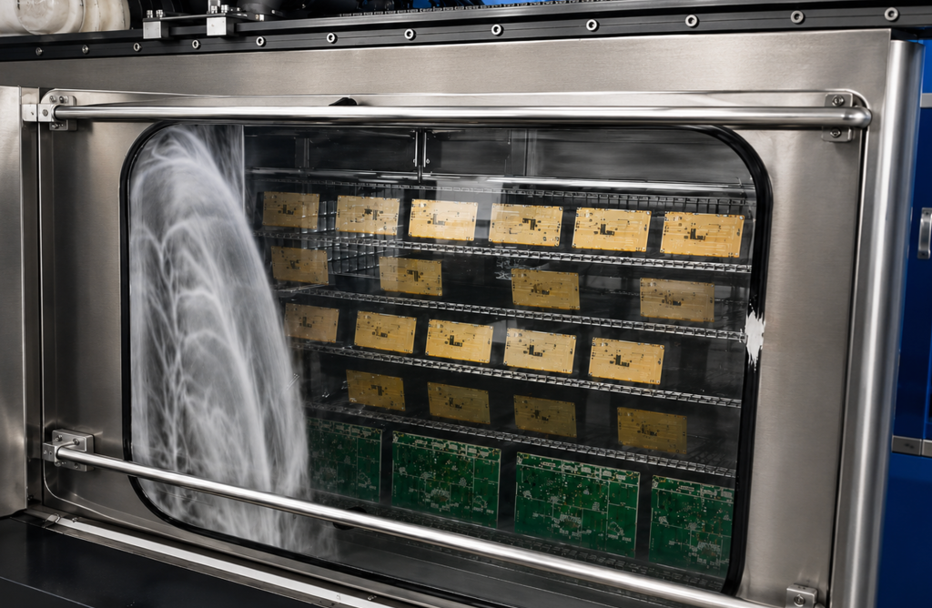
A properly prepared PCBA surface supports:
- Consistent coating adhesion
- More uniform coverage
- Stable curing
- Cleaner film condition
- Better long-term environmental protection
Before application, the manufacturing process should control:
- Flux residue
- Dust and loose particles
- Oils and fingerprints
- Handling contamination
- Moisture
- Surface compatibility
- Adhesion condition
Removing unwanted residue before application helps the protective film perform as intended. It also supports more consistent coverage and reduces the risk of contamination remaining beneath the coating.
The required surface condition and cleaning acceptance method should be defined before coating begins. The coating material should also be compatible with the board, components, markings, adhesives, and other approved materials present on the assembly.
Cleaning, surface treatment, application, and curing should therefore be treated as a connected process rather than as separate production steps.
RF SKYPOWER’s documented manufacturing process connects the following stages:
Deep purification cleaning → Surface treatment → Conformal coating application → Conformal coating curing → Reliability verification
Each stage contributes to the quality of the finished protective layer.
Cleaning and surface treatment prepare the PCBA, controlled application establishes the required coverage, and curing, inspection, and subsequent testing complete the process evidence.
This approach makes conformal coating more than a visible manufacturing feature. It makes the process a controlled part of RF PA environmental-reliability management.
5. How to Control Manual Brush Application on RF PA PCBAs
This application method is well suited to RF PA PCBAs with complex layouts, sensitive connectors, grounding points, thermal interfaces, test locations, and service areas.
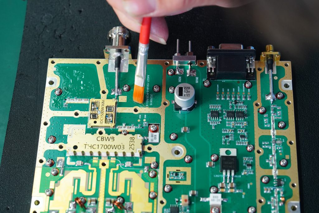
This method is particularly useful when:
- Different PCBAs use different layouts
- Production includes multiple frequency or power configurations
- Coating must be applied around closely spaced components
- Specific interfaces must remain clear
- Custom modules require board-specific coverage
- Service or adjustment areas must remain accessible
The operator can apply the coating directly to the required areas while following the approved process drawing.
A board-specific keep-out map helps protect the required PCBA surfaces while keeping electrical, mechanical, RF, and thermal interfaces clear.
Typical controlled locations may include:
- RF connector contacts
- DC and control connector contacts
- Grounding surfaces
- Screw-contact areas
- Test and adjustment points
- Thermal interfaces
- Service and repair locations
The application process should control:
- Required coverage
- Edge condition
- Bubbles and voids
- Pooling
- Wicking into restricted areas
- Local film consistency
- Operator repeatability
The objective is to produce controlled coverage that matches the actual board design and environmental requirement.
A complete manual application process connects:
- A board-specific coating drawing
- Defined coverage areas
- Defined keep-out zones
- Approved application instructions
- Finished-film inspection
- Controlled rework requirements
Manual brush application can accommodate board-specific coating boundaries when coverage, keep-out zones, application instructions, inspection, and rework criteria are clearly controlled.
The coating plan can therefore be adapted to the module’s board layout, connector arrangement, grounding design, cooling structure, service requirements, and deployment environment.
6. How Curing, Inspection, and RF Verification Complete the Process
RF PA conformal coating reaches its release stage after the material has met the specified process condition and the finished assembly has completed the required inspection and verification.
The process record should identify the coating material, application or batch information, curing condition, required waiting period, and release status.
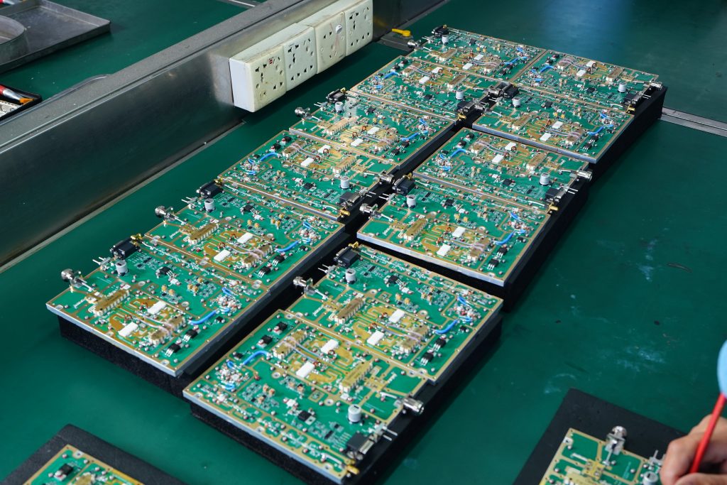
After curing, inspection can confirm:
- Required coverage
- Clear keep-out zones
- Consistent film condition
- Acceptable bubbles, voids, and pooling
- Clear connectors and controlled interfaces
- No visible contamination or mechanical damage
The inspection method should match the selected coating material and acceptance plan. Depending on the process, this may include normal visual examination, UV-assisted inspection, or another approved method.
Inspection confirms the physical coating condition. Post-coating testing confirms the performance of the completed RF PA assembly.
The applicable verification may include:
- RF output
- Gain and gain flatness
- Vdc and Idc
- FWD, REV, and VSWR
- Enable and control response
- Alarm and protection status
- Connector operation
The results should be checked under defined test conditions and compared with the applicable acceptance limits.
The purpose is not to require every value to remain numerically identical before and after coating. The purpose is to confirm that the finished assembly remains within its approved RF, DC, control, and protection boundaries.
Curing, inspection, and post-coating RF verification together support the release decision for the completed RF PA assembly.
For shipment approval, these records can be reviewed together with the wider C-UAS RF PA acceptance checklist and linked to the delivered module serial number.
How to Define Conformal Coating in an RFQ
A well-defined RFQ converts conformal coating from a general requirement into a clear and verifiable manufacturing specification.
The RFQ can define both the board-level process and the complete environmental-protection boundary.
PCBA-Level Requirements
These may include:
- Cleaning and surface preparation
- Approved coating material or required performance
- Application method
- Required coverage
- Keep-out zones
- Film or process limits
- Curing condition
- Inspection method
- Rework process
- Post-coating RF verification
Module- and System-Level Requirements
Depending on the project configuration, these may include:
- Enclosure protection
- RF connector protection
- DC and control interface protection
- Cable-entry design
- Drainage
- Condensation control
- Cooling
- Installation orientation
- Cabinet environment
- Service access
RF PA Conformal Coating RFQ Checklist
| RFQ item | Customer input needed | What it defines |
|---|---|---|
| Deployment environment | Indoor, outdoor cabinet, rooftop, airport, border, vehicle, or other location | Environmental operating boundary |
| Humidity and condensation | Expected humidity variation and condensation risk | Board- and module-level protection requirements |
| Dust, salt, or chemical exposure | Relevant airborne contaminants | Required environmental resistance |
| Cleaning requirement | Required pre-coating surface condition | Surface-preparation control |
| Coating material | Approved material or required performance | Protective-film requirement |
| Application method | Manual brush, selective application, spray, or project-defined method | Manufacturing approach |
| Coverage drawing | Areas requiring coating | Required board-level protection |
| Keep-out drawing | Connectors, grounding points, test points, thermal surfaces, and service areas | Controlled uncoated interfaces |
| Film requirement | Dry-film thickness or approved process limit, where applicable | Finished coating condition |
| Cure condition | Time, temperature, and release state | Process completion requirement |
| Inspection method | Visual, UV, or project-defined inspection | Coverage and film verification |
| Defect criteria | Limits for bubbles, voids, pooling, missed areas, and contamination | Objective acceptance criteria |
| Rework process | Cleaning, repair, recoating, and retesting | Controlled repair method |
| Post-coating RF test | RF, DC, control, and protection parameters | Finished-module performance verification |
| Enclosure and interface protection | Mechanical and connector requirements | Complete environmental-protection boundary |
| Traceability | Process, inspection, test result, and S/N | Delivery evidence |
A strong supplier review should ask:
What coating process is used, where is it applied, which locations are controlled as keep-out zones, how is it cured and inspected, and which post-coating results are linked to the delivered module?
For standard or custom RF PA projects where conformal coating is specified, the coating and inspection plan should match the actual PCBA layout, connectors, grounding structure, cooling method, enclosure, service requirements, and deployment environment.
Once the operating environment and protection boundary are defined, the required frequency, output power, PCBA coating, enclosure, cooling method, interfaces, and report package can be reviewed through the Custom RF Power Amplifier Modules engineering process.
Conclusion
RF PA conformal coating provides an important layer of board-level environmental protection by reducing PCBA exposure to moisture, dust, oxidation, and airborne contamination.
Its value becomes stronger when it is supported by controlled cleaning, surface preparation, selective application, keep-out management, curing, inspection, post-coating RF verification, and module-level environmental design.
The complete manufacturing and acceptance chain is:
Cleaning → Surface preparation → Selective coating → Curing → Inspection → Post-coating RF verification
Together, these steps create a traceable environmental-reliability process for RF PA modules intended for demanding C-UAS deployments.
For outdoor cabinets, rooftops, airports, border sites, vehicle-mounted systems, high-humidity locations, and other complex environments, provide the deployment conditions, condensation risk, cabinet structure, connector type, frequency range, output power, cooling method, and acceptance requirements to RF SKYPOWER for engineering review.