











RF PA vibration testing should not be treated as complete simply because a module remains secured, shows no visible damage, and still powers on after exposure. An RF PA can pass its full-power bench test before shipment and still develop intermittent problems after long-distance transportation, vehicle installation, or repeated mechanical vibration.
The module may continue to power on, but its RF output begins to fluctuate. A control alarm may appear only when a cable or enclosure is moved. Re-tightening a connector may temporarily remove the symptom without identifying what changed.
The useful approval question is whether the RF PA still meets its defined RF, DC, control, protection, and mechanical limits after the required vibration exposure.
A complete vibration acceptance process should connect four stages:
Pre-test baseline → Defined vibration exposure → Mechanical inspection → Post-vibration RF verification
1. Why a Bench RF Test Does Not Cover Vibration Risk
A bench RF test verifies module performance while the hardware remains stationary under controlled RF, DC, load, and cooling conditions.

It can establish a baseline for:
- RF output
- Gain and gain flatness
- Supply voltage and current
- Forward and reflected power
- VSWR
- Control response
- Alarm and protection status
However, a static electrical test does not evaluate how repeated mechanical movement may affect connectors, cable support, mounting points, fasteners, grounding contacts, shielding pressure, or internal assembly interfaces.
The two tests answer different questions.
A bench RF test asks:
Does the module meet its electrical requirements while stationary?
A vibration test asks:
Does the module remain mechanically and electrically acceptable after the defined dynamic exposure?
Neither result can replace the other.
A bench RF test confirms performance under a stationary condition. It does not prove that the same performance will remain after transportation or operating vibration.
The pre-vibration result should therefore be treated as the comparison baseline. After the mechanical exposure, the applicable measurements should be repeated using an equivalent full-power RF PA test method.
RF input level, test frequencies, load condition, cables, attenuation, correction method, cooling boundary, test equipment, and measurement reference plane should remain controlled wherever possible.
Without this comparison, the test may confirm that the module experienced mechanical vibration, but not that its RF performance remained acceptable afterward.
2. Why Vibration Testing Matters for RF PA Modules
RF PA modules are not always used in a stationary laboratory environment.
Before reaching the final installation, a module may experience long-distance transportation, repeated loading and unloading, vehicle movement, cabinet vibration, or mechanical force transferred through attached cables and mounting structures.
These conditions can affect more than the external enclosure.
Repeated vibration applies stress to interfaces that carry RF energy, DC power, control signals, grounding, shielding, heat, and structural load. A small change at one interface may not be visible from the outside, but it can still affect RF output stability, supply current, control communication, reflected power, or protection status.
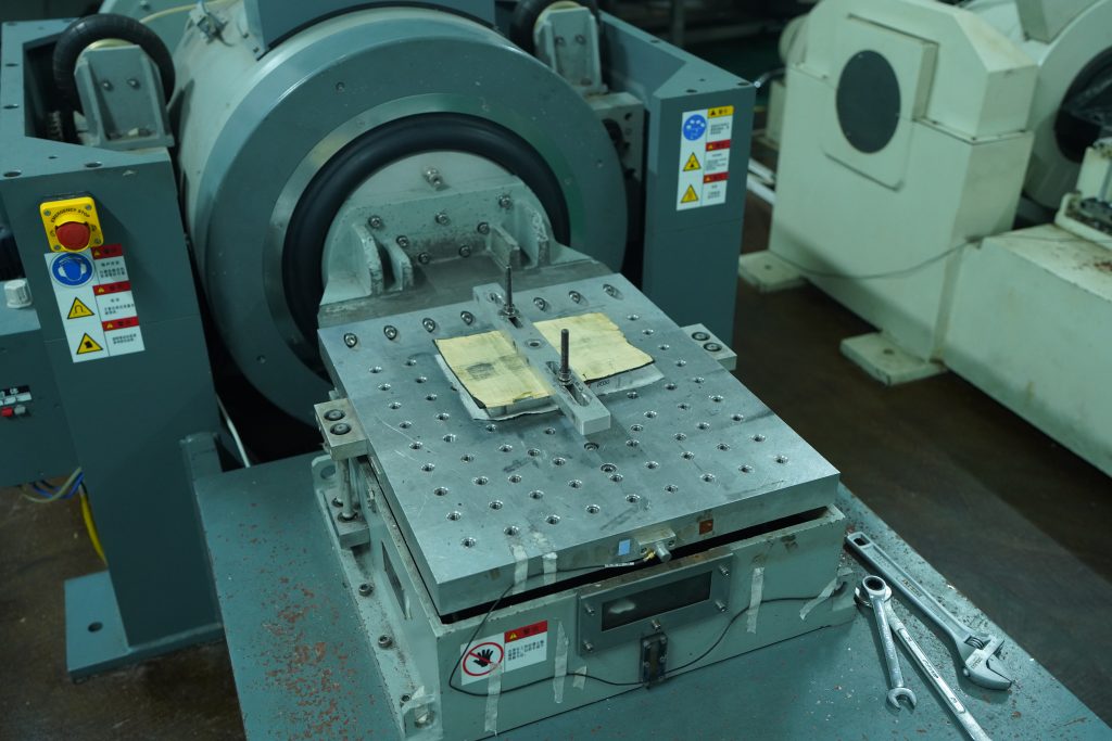
This is particularly relevant to:
- Vehicle-mounted C-UAS equipment
- Mobile and temporary deployment systems
- Equipment transported between project locations
- Cabinets installed near generators, fans, or rotating machinery
- Modules connected to heavy or insufficiently supported RF cables
A connector may remain physically attached but develop intermittent contact. A cable may continue to look secure while applying additional force to its mating interface. A fixing point may shift slightly without creating visible enclosure damage.
These changes do not mean that every module exposed to vibration will fail. They explain why mechanical exposure and static RF performance should be evaluated as separate but connected approval boundaries.
Completing the vibration exposure is only one part of that process. The module should also be inspected and retested afterward.
The final judgment should determine whether RF output, gain, Vdc, Idc, FWD, REV, VSWR, control response, alarm status, protection behavior, connectors, and mounting points remain within their acceptance limits.
Vibration testing is therefore not only a check that the enclosure survives mechanical movement. It is part of the evidence used to confirm that the RF PA can still perform its required function after the defined exposure.
3. Transport, Unpowered Equipment, and Powered Vibration Tests Are Different
Once the need for vibration testing is established, the next question is what type of vibration evidence the project actually requires.
“Vibration tested” does not describe one universal condition.
The result depends on:
- Whether the shipping package or the module itself is tested
- How the hardware is mounted
- Whether the RF PA remains powered
- Which mechanical vibration profile is applied
- Whether performance is checked during or after exposure
For RF PA qualification, three categories should be distinguished.
Packaged Transport Vibration
A packaged transport vibration test evaluates the RF PA inside its final shipping configuration.
The test boundary may include:
- Shipping carton or transport case
- Foam and internal support materials
- Module orientation inside the package
- Packaging restraints and fixation
- Conditions representing road, air, or long-distance logistics
The main purpose is to determine whether the packaging protects the delivered module from unacceptable mechanical or electrical change during transportation.
The result applies to the complete packaged configuration.
It does not automatically prove that the unpackaged module can withstand vibration after installation because the carton, foam, and internal supports affect how vibration reaches the hardware.
Unpowered Equipment-Level Vibration
In an unpowered equipment-level vibration test, the RF PA is mounted directly to a controlled fixture without its shipping package.
The module is not electrically operating while the mechanical exposure is applied.
This method evaluates the structural and assembly integrity of the module itself, including:
- Enclosure and mounting holes
- RF, DC, and control connectors
- PCB and internal component fixation
- Fasteners and internal cable support
- Grounding and shielding contacts
- Other assembly interfaces
In this configuration, the module itself—not its transport packaging—is the test item.
For the specific unpowered equipment-level profile referenced in this article, the RF PA is subjected to random vibration from 15 Hz to 2000 Hz along the X, Y, and Z axes. Each axis is tested for two hours, with a specified PSD of 0.04 g²/Hz, giving a total specified exposure time of six hours.
Because this profile is specified using PSD across a mechanical frequency range, it is a random-vibration profile rather than a sine sweep. PSD describes how vibration energy is distributed across that defined frequency range. PSD, or power spectral density, describes how vibration energy is distributed across the specified mechanical frequency range.
Because the module is tested without its transport packaging, the result evaluates the equipment structure rather than the protection provided by a carton, foam, or transport case.
Because the RF PA remains unpowered during exposure, this test cannot directly detect:
- Momentary RF output variation
- Temporary DC power interruption
- Control communication loss
- Alarm events during vibration
- Intermittent contact that appears only under live operation
Its acceptance value therefore depends on the inspection and RF verification completed afterward.
The module should undergo mechanical inspection and post-vibration RF testing to confirm that the applicable output, gain, current, VSWR, control response, protection status, connectors, and mounting interfaces remain within their defined limits.
Powered Operating Vibration
A powered operating vibration test evaluates the RF PA while it remains electrically active in a configuration closer to its intended installation.
Depending on the project, the setup may include:
- DC power
- Control communication
- RF input
- RF output or a controlled load
- Alarm and status monitoring
- Representative cable support
- Project-defined mounting orientation
This method can reveal temporary operating conditions that an unpowered test cannot capture, such as:
- Momentary DC interruption
- RF output fluctuation
- Control communication loss
- Intermittent connector contact
- Unexpected alarm or protection events
A powered test provides additional evidence about behavior during vibration, but it also requires a more complex and carefully controlled RF, DC, control, load, and monitoring setup.
These three categories should not be treated as interchangeable.
A packaged transport test evaluates the shipping configuration. An unpowered equipment-level test evaluates the mechanical integrity of the unpackaged module and verifies its condition after exposure. A powered operating test evaluates whether the module continues to function while vibration is being applied.
The RFQ and test report should identify the test category, vibration profile, mounting condition, powered state, and required post-test evidence instead of stating only that the module is “vibration tested.”
4. Which RF PA Interfaces Should Be Checked After Vibration
The most important post-vibration checks are often the interfaces that connect RF energy, DC power, control signals, grounding, shielding, and the module structure.
RF input and output connections
RF connectors should be checked for:
- Looseness or rotation
- Damaged threads
- Changed mounting pressure
- Cable strain near the connector
- Movement relative to the enclosure
- Intermittent contact during cable movement
The mating cable assembly should also be considered.
A heavy or unsupported RF cable can apply additional mechanical load to the module connector during transportation or installed operation. A connector may appear visually intact while its contact or mounting condition has changed enough to affect measurement repeatability.
DC power and control connections
Power and control interfaces should be checked for secure engagement, pin condition, harness support, and intermittent behavior.
A module may continue to generate RF while an enable, alarm, or communication connection has become unreliable.
These faults can create field symptoms that appear only when a cable is moved, the enclosure changes orientation, or vibration is applied again.
Mechanical and internal assembly boundaries
Depending on the module design and inspection scope, the review may also include:
- Internal cable routing and strain relief
- PCB or amplifier-board fixation
- Enclosure screws and mounting holes
- External brackets
- Grounding and shielding contacts
- Heatsink attachment
- Thermal-interface compression where it is part of the inspected assembly boundary
These checks should not assume that vibration has caused damage.
Their purpose is to confirm whether the approved mechanical and electrical condition has been maintained.
“Nothing is visibly broken” is not a complete acceptance statement.
The more useful conclusion is:
The critical RF, DC, control, grounding, and structural interfaces remained within their defined mechanical and electrical limits.
5. Why Pre-Test and Post-Test RF Data Must Be Comparable
Useful RF PA vibration testing depends on measurements that can be compared before and after exposure.
The applicable parameters defined in the acceptance plan should be measured under equivalent conditions at both stages.
These parameters may include:
- RF test frequency
- RF input drive
- RF output
- Gain and gain flatness
- Vdc and Idc
- FWD and REV power
- VSWR
- Enable and control response
- Alarm status
- Protection status
The comparison method matters as much as the selected parameters.
RF input level, dummy load, cables, attenuation, correction method, measurement reference plane, test equipment, and cooling condition should remain controlled wherever possible.
Otherwise, a change in the test setup may be mistaken for a vibration-related change.
The values do not need to remain numerically identical. Normal measurement variation may occur.
The acceptance plan should define:
- The permitted parameter range
- The permitted change from baseline
- Conditions requiring inspection or retesting
- Conditions resulting in rejection
For example, a post-vibration output result may remain above the minimum limit but show an unusual change compared with the original baseline.
That result may justify checking connector fixation, RF cable condition, supply current, reflected power, gain shape, and mounting support before final approval.
A meaningful comparison should answer three questions:
- Does the module still operate?
- Do the applicable parameters remain within their acceptance limits?
- Has an unusual change appeared that may indicate an intermittent or developing interface problem?
Mechanical survival is not enough.
The post-vibration RF check determines whether the module still performs as an RF device, not merely whether it remains physically assembled.
6. What a Useful Vibration Test Report Should Record
A useful report should allow the buyer to reconstruct the test boundary and understand how the module was evaluated before and after vibration.
It should connect the vibration condition, mounting configuration, measured results, and acceptance decision to one identifiable module.
RF PA Vibration Acceptance Evidence
| Evidence group | Recommended fields | What it confirms |
|---|---|---|
| Module identity | Model, S/N, test date, operator | The result belongs to an identifiable test unit |
| Test purpose | Packaged transport, unpowered equipment-level, or powered operating vibration | The environmental boundary being evaluated |
| Test configuration | Packaged or unpackaged state, fixture ID, mounting orientation, cable support | How the module was secured and connected |
| Vibration condition | Mechanical frequency range, PSD, acceleration, displacement or Grms, test axes, duration | The specified and recorded mechanical exposure |
| Powered state | Powered or unpowered during vibration | Whether live operation was evaluated |
| Pre-test baseline | RF output, gain, Vdc, Idc, FWD, REV, VSWR, control and protection status | The module condition before exposure |
| Mechanical inspection | Connectors, fasteners, enclosure, mounting points, cables, and harnesses | Whether mechanical changes were identified |
| Post-test verification | Repeated RF, DC, control, and protection measurements | Whether performance remained acceptable |
| Acceptance criteria | Permitted limits and allowed change | How PASS or FAIL was determined |
| Final result | PASS, FAIL, retest, or engineering review | The final release decision |
The report should use mechanical vibration frequency when describing shaker movement and RF test frequency when describing the radio-frequency measurement.
This prevents two different meanings of “frequency” from being mixed.
In practical terms:
- Mechanical vibration frequency describes how quickly the vibration changes.
- PSD describes how vibration energy is distributed across the mechanical frequency range.
- Acceleration or Grms describes vibration severity.
- Test axis describes the direction of exposure.
- RF test frequency describes where the amplifier is measured within its operating band.
- The fixture defines how the module is attached to the vibration table.
A useful report connects the vibration profile, mounting condition, exposure time, mechanical inspection, and pre-test/post-test RF results to one module S/N.
These fields can become part of a broader C-UAS RF PA acceptance checklist rather than remaining an isolated environmental test record.
7. How to Write Vibration Requirements into the RFQ
The RFQ should not ask only whether the supplier has a vibration table or offers vibration testing.
It should define which condition must be applied and what evidence must be provided afterward.
RF PA Vibration Test RFQ Checklist
| RFQ item | Customer input needed | What it confirms |
|---|---|---|
| Test category | Packaged transport, unpowered equipment-level, or powered operating vibration | Defines the required evidence boundary |
| Test method | Specified standard or project-defined profile | Establishes the procedure |
| Vibration type | Random vibration, sine sweep, or another defined method | Defines how vibration is applied |
| Mechanical frequency range | Required vibration frequency range | Defines the mechanical spectrum |
| Vibration severity | PSD, acceleration, displacement, or Grms | Defines test intensity |
| Test axes | Required X, Y, and Z coverage | Defines directional exposure |
| Duration | Required time per axis | Defines total exposure |
| Mounting condition | Fixture, bracket, and module orientation | Connects the test to the installation |
| Packaging condition | Packaged or unpackaged | Separates transport and equipment-level evidence |
| Powered state | Powered or unpowered | Defines whether live performance is evaluated |
| Cable support | RF, DC, and control cable arrangement | Controls connector and harness stress |
| Pre-test evidence | Required RF, DC, control, and protection fields | Establishes the baseline |
| Post-test evidence | Measurements repeated after exposure | Verifies retained performance |
| Acceptance limits | Permitted values and allowed change | Establishes objective PASS or FAIL criteria |
| Inspection scope | Connectors, housing, fasteners, mounting points, and cables | Defines the mechanical review |
| Report format | Profile, measurements, limits, result, and S/N | Creates traceable delivery evidence |
| Failure response | Retest, analysis, repair, or rejection process | Defines the action after a failed result |
Statements such as “harsh vibration tested,” “military-grade vibration,” or “shaker test passed” are not sufficient without a defined test profile and acceptance record.
The more useful RFQ question is not:
Do you perform vibration testing?
It is:
Which vibration condition will be applied, and which post-test measurements will prove that the module remains acceptable?
RF SKYPOWER supplies standard and custom RF PA modules across multiple wideband frequency ranges and 30W to 200W power levels.
Vibration acceptance should be matched to the selected module structure, mass, mounting direction, connector layout, transportation method, and deployment platform.
Once these boundaries are defined, the required frequency range, output power, enclosure, connector arrangement, cooling method, control interface, and test documentation can be reviewed through the Custom RF Power Amplifier Modules engineering process.
Conclusion
An RF PA remaining attached to a vibration fixture does not prove that its RF performance remained acceptable.
A useful vibration approval process combines a defined mechanical profile, controlled mounting condition, pre-test baseline, post-test inspection, comparable RF measurements, and S/N-linked evidence.
The final result should show whether RF output, gain, current, reflected power, VSWR, control response, protection status, connectors, and mounting interfaces remain within their approved limits after vibration exposure.
For packaged transport, unpowered equipment-level, powered operating, vehicle-mounted, mobile, or fixed-site projects, provide the required frequency range, output power, mounting direction, packaging method, connector layout, vibration profile, powered state, and acceptance criteria to RF SKYPOWER for engineering and RFQ review.