










A wideband RF PA module may start normally, reach the expected output, and produce a clean gain curve at 25°C. That result is useful, but it proves performance at only one temperature.
It does not prove that the module can start at -40°C, remain within its RF and DC limits at +60°C, or recover normally after thermal exposure.
For a C-UAS installation, these conditions are not theoretical. A fixed-site module may face a winter cold start, a solar-heated outdoor cabinet, restricted airflow, or continuous operation after internal heat has built up.
Reliable RF PA temperature testing should therefore do more than expose the module to a temperature chamber. During each powered operating stage, the applicable RF, DC, control, and protection parameters should be measured under the defined temperature and test conditions.
If the design boundary is a known 50°C ambient site, use the 50°C RF power amplifier site-selection guide to translate enclosure heat, duty cycle, cooling, supply, and required output into RFQ requirements. This temperature-testing article remains focused on laboratory qualification and acceptance evidence.
The central distinction is simple:
A room-temperature result confirms performance at one convenient condition, while temperature qualification checks whether the module remains within defined acceptance limits across the required thermal boundary.
1. Why a Room-Temperature RF Test Can Create False Confidence
A room-temperature test provides an important baseline. It confirms that the test unit can power on, accept an RF input, and produce measurable output under the conditions present at that moment.
The mistake is treating that baseline as complete approval evidence.
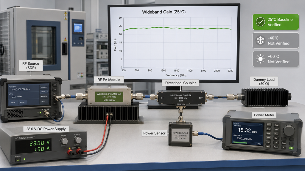
A successful 25°C test does not automatically confirm:
- Reliable low-temperature startup
- Stable output after internal heat builds up
- Acceptable gain variation across temperature
- Normal current demand at the thermal boundaries
- Consistent control and alarm response
- Full-band performance at low and high temperature
- Normal recovery after thermal exposure
A short room-temperature measurement can also hide conditions that develop only after longer operation. Device temperature, bias behavior, current, gain, and protection status may change as the module approaches thermal equilibrium.
This is especially relevant in outdoor or enclosed installations. A module that performs well on an open laboratory bench may operate under a different thermal boundary once it is mounted inside a cabinet with limited airflow.
Keep the room-temperature result as the comparison baseline, not as evidence for untested thermal conditions.
The room-temperature result should therefore remain the baseline against which low-temperature, high-temperature, and recovered-room-temperature measurements are compared. Where continuous operation is part of the approval requirement, the room-temperature baseline should also be compared with a defined RF PA thermal-soak test.
2. Why Temperature Exposure Alone Is Not Enough
Exposing an RF PA module to a low- or high-temperature environment can show that the hardware withstands the condition. It does not show how the module behaves while generating RF power.
During powered operation, two thermal conditions act on the module at the same time:
- The surrounding environmental temperature
- The heat generated inside the RF PA
This combined condition is closer to actual deployment than unpowered chamber exposure or a quick startup check.
At the low-temperature boundary, the module may need to start before its internal components have warmed. Bias behavior, control response, supply current, gain, and RF output should reach their defined operating ranges without abnormal delay or protection events.
At the high-temperature boundary, startup may appear normal while internal heat continues to build. Output, gain, current, case temperature, and protection status may move closer to their acceptance limits as the module approaches a stable thermal condition.
This is why a brief power-on result is not enough. The module should remain powered for the stabilization period defined in the test plan, while the applicable RF, DC, control, and protection parameters are recorded.
The purpose is not to prove that every measured value remains numerically identical at all temperatures. The purpose is to confirm that the module continues to perform its required function within the approved limits.
Powered temperature testing therefore answers the practical approval question:
Can the RF PA start, operate, and maintain acceptable performance under the thermal conditions expected in the final installation?
3. Operating Temperature Is Not the Same as Storage Temperature
Operating temperature and storage temperature represent different test conditions. They should not be combined in one statement or used as interchangeable evidence.
For the 300–2700 MHz RF PA family referenced in this article, the documented temperature boundaries are separated as follows:
- Operating temperature: -40°C to +60°C
- Storage temperature: -55°C to +85°C
Storage temperature describes the environmental boundary that an unpowered module can withstand during storage or transportation.
A storage result does not automatically prove that the RF PA can:
- Start at that temperature
- Produce its required RF output
- Maintain acceptable gain
- Draw normal current
- Respond correctly to control commands
- Preserve normal alarm and protection behavior
Operating-temperature qualification requires the module to be powered and evaluated under the defined environmental condition.
Surviving storage at an extreme temperature does not prove that the RF PA can start, produce output, and maintain stable parameters while operating at that temperature.
For example, a qualification sequence may expose an unpowered module to -55°C and later test powered operation at -40°C. These are two different stages.
The report should not describe that sequence as operation at -55°C.
The same distinction applies at the upper boundary. Exposure to +85°C during an unpowered storage stage does not prove that the module produced RF output while operating at +85°C.
A clear report should identify each stage separately:
- Storage or environmental exposure
- Stabilization or soak
- Powered operating test
- Recovery to room temperature
- Post-test RF verification
This separation helps buyers compare supplier reports correctly. It also prevents a wider storage rating from being mistaken for a wider powered operating capability.
4. Which Parameters Should Be Recorded at the Powered Temperature Boundaries?
Temperature qualification should not end with the statement that the module remained powered on.
The applicable parameters defined in the acceptance plan should be recorded and compared at each required operating condition.
RF performance
The RF measurements may include:
- Test frequency
- RF input level
- Measured RF output
- Gain
- Gain flatness
- Forward power
- Reflected power
- VSWR
These fields show whether the module continues to meet the defined RF limits under the specified chamber condition.
Forward and reflected power should be interpreted together. Forward power shows the RF energy sent toward the load, while reflected power shows whether part of that energy is returning from the RF path.
For an initial module baseline, a controlled 50-ohm dummy-load test setup reduces uncertainty from an external feeder, antenna, connector, or changing load condition.
DC and thermal behavior
The applicable DC and thermal fields may include:
- Supply voltage
- Supply current
- Module or case temperature
- Chamber setpoint
- Actual chamber temperature
- Stabilization time
- Measurement time
Supply current adds useful context to the RF result. A module may still produce acceptable output while drawing more current or moving closer to a thermal boundary.
The chamber setpoint should also be distinguished from the actual recorded chamber temperature. Approval should rely on the condition measured during the test, not only the value entered into the chamber controller.
Control and protection behavior
Depending on the selected module configuration and project requirements, the test may also record:
- Enable response
- Control-command response
- Alarm status
- Temperature status
- Protection status
- Foldback or shutdown state
- Recovery after the condition returns to normal
For a 28V DC RF PA with temperature, voltage, VSWR, or reflected-power protection, the acceptance procedure should define which states are expected during normal operation and how a protection event should be recorded.
A module that still produces RF output but reports an incorrect alarm state may create an integration problem. The interpretation and timing of these signals should remain consistent with the approved control and alarm interface.
Temperature does not have to leave every measured value numerically unchanged. The correct acceptance question is whether the applicable measurements remain within the project-defined limits.
5. Why Full-Band Testing Matters More Than One Frequency Point
A wideband RF PA should not be approved from one convenient center-frequency measurement.
Passing one frequency at -40°C and +60°C does not prove that the entire required band remains within its output and gain limits.
Different parts of a wide operating band may not respond identically to temperature. A variation may appear near a band edge, around a matching transition, or at a project-critical operating frequency even when the center-frequency result remains acceptable.
This does not mean that low temperature or high temperature will always cause a specific frequency-related failure. The result must be determined from the measured sweep rather than assumed in advance.
A practical full-band test plan should include:
- The low-frequency band edge
- One or more center-band frequencies
- The high-frequency band edge
- Project-critical operating frequencies
- Frequencies where the room-temperature baseline shows a gain or output transition
For a 300–2700 MHz module, a single result near the center of the band cannot represent the complete wideband response. A defined multi-point or automated sweep can provide broader frequency evidence when the required input drive, measurement reference planes, correction method, thermal state, and any necessary dwell or stabilization conditions remain controlled.
The comparison is most useful when it includes:
- Room-temperature baseline
- Low-temperature operating sweep
- High-temperature operating sweep
- Recovered room-temperature sweep
The recovered-room-temperature measurement helps determine whether a difference was temporary or remained after the module returned to normal conditions.
The measurement method should remain equivalent across the four stages. RF input level, reference plane, cable correction, attenuation, measurement equipment, and test sequence should be controlled so that a setup change is not mistaken for a temperature effect.
Full-band RF PA temperature testing should also be reviewed together with the cooling and duty boundary. The chamber controls the surrounding environmental condition, while the RF PA continues to generate internal heat during powered operation.
Ambient temperature, RF output, efficiency, operating time, heat spreading, heatsink structure, and airflow therefore remain connected parts of the RF PA thermal boundary.
6. What Temperature-Test Evidence Should Be Required Before Shipment
A useful temperature report connects the chamber condition, stabilization period, RF measurements, module identity, and acceptance result.
High and Low Temperature RF PA Acceptance Evidence
| Evidence field | What it confirms |
|---|---|
| Module model and S/N | The result belongs to the actual tested module |
| Test type | Whether the stage was operating, storage, cycling, or recovery |
| Chamber setpoint | The environmental condition requested by the procedure |
| Actual chamber temperature | The recorded environment during measurement |
| Stabilization or soak time | The measurement was not taken immediately after the setpoint changed |
| Measurement time | When the result was recorded within the test sequence |
| Test frequency or sweep range | Which part of the operating band was checked |
| RF input level | Whether the comparison used an equivalent drive condition |
| Measured RF output | The actual output under the defined condition |
| Gain and gain flatness | Whether wideband amplification remained within limits |
| Vdc and Idc | Whether the electrical operating condition remained acceptable |
| FWD, REV, and VSWR | The forward-output and reflected-power conditions |
| Module or case temperature | The module’s thermal state during operation |
| Alarm and protection state | Whether an abnormal, foldback, or shutdown state occurred |
| Recovery result | Whether performance returned to the accepted room-temperature range |
| Acceptance limit and result | Why the measured condition was marked PASS or FAIL |
| Test report and S/N | Traceability between the evidence and the delivered unit |
A useful temperature report connects chamber condition, stabilization time, RF measurements, protection status, and module serial number in one traceable record.
RF SKYPOWER’s 300–2700 MHz RF PA family includes 30W, 50W, 100W, 150W, and 200W configurations. The required temperature evidence should be matched to the selected power level, cooling structure, duty condition, voltage boundary, protection configuration, and acceptance plan.
This is where the topic moves from testing to selection.
Once the operating temperature and evidence boundary are defined, module selection should consider the required frequency range, usable output, DC supply boundary, cooling method, RF load, protection behavior, and delivery documentation together.
Rated output alone is not enough to define a suitable module. These engineering conditions form a more reliable C-UAS RF PA selection starting point.
RFQ Checklist
| RFQ item | Customer input needed | What it confirms |
|---|---|---|
| Required operating band | Minimum and maximum operating frequencies | Defines the sweep range and band-edge test points |
| Required RF output | Target output and permitted variation | Defines the acceptance limit at each temperature |
| Operating-temperature range | Lowest and highest powered operating conditions | Separates operating qualification from storage exposure |
| Storage-temperature range | Required unpowered environmental boundary | Defines storage or transportation exposure |
| Duty condition | Continuous, intermittent, or project-defined operation | Establishes the thermal load during testing |
| Cooling boundary | Heatsink, airflow, cabinet, and mounting information | Connects chamber testing to the final installation |
| DC input boundary | Nominal voltage and permitted range | Defines Vdc and Idc test conditions |
| RF load condition | Dummy load, feeder, antenna, or project-defined load | Clarifies the RF measurement boundary |
| Protection requirements | Temperature, voltage, VSWR, and reflected-power behavior | Defines alarm, foldback, and shutdown checks |
| Stabilization time | Required time before each measurement | Prevents testing before the condition has stabilized |
| Frequency test points | Band edges, center frequencies, and critical channels | Prevents single-frequency approval |
| Acceptance limits | Permitted output, gain, current, VSWR, and alarm states | Establishes objective PASS or FAIL criteria |
| Recovery requirement | Post-test room-temperature verification | Checks whether performance returns to the approved baseline |
| Required report format | Data fields, plots, limits, result, and module S/N | Creates traceable delivery evidence |
The RFQ should state whether the customer requires type-level qualification, batch-level evidence, or an individual report matched to each delivered serial number.
These fields can be incorporated into an RF PA acceptance checklist that connects the requested temperature boundary with the evidence reviewed before shipment.
Conclusion
A successful room-temperature test is an important baseline, but it is not sufficient when RF PA approval requires operation beyond that room-temperature condition.
The correct review asks whether the module can start, produce the required output, maintain acceptable gain and current, preserve normal control and protection behavior, and remain within its limits at the defined low- and high-temperature operating conditions.
Approval should also distinguish operating temperature from storage temperature, compare the full required frequency band, document stabilization time, and connect the result to the tested module S/N.
To review your frequency range, output target, duty cycle, cooling boundary, operating and storage temperatures, protection behavior, and required test evidence before final module approval, contact RF SKYPOWER for an engineering and RFQ review.