










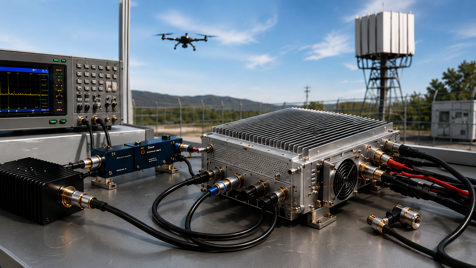
Drone jammer module burnout risk exists when operating conditions can exceed the validated thermal, RF-load, or DC boundary of the RF PA. If the protection response cannot be verified under that condition, the buyer cannot conclude that the risk is controlled.
A short bench test may still look normal while a longer duty cycle, an installed antenna path, or PA-side voltage drop introduces a different stress condition. Control and restart behavior can also repeatedly expose the PA to an unresolved stress condition even when the original fault has already triggered protection.
Alarm visibility and test traceability do not physically cause burnout. They determine whether the buyer can see what happened, isolate the relevant boundary, and prove that the risk is controlled.
Before RFQ or system integration, first confirm the wider drone jammer module system boundary, then identify the direct physical stress source. Then check whether the protection and recovery behavior limits that stress and whether the available evidence supports the required decision. If the operating boundary or evidence is incomplete, the correct conclusion is cannot conclude yet.
1. What Drone Jammer Module Burnout Risk Really Means
Burnout is a failure result, not a root-cause diagnosis.
For buyer-side analysis, three direct physical stress branches should be separated first:
- Thermal / duty-cycle stress: heat accumulates beyond the validated cooling and operating boundary.
- RF-load / VSWR stress: the PA is exposed to a load or reflected-power condition outside the required RF boundary.
- DC / electrical stress: the module sees voltage, current, startup, or transient conditions outside the required electrical boundary.
A fourth issue—control / restart behavior—belongs to a different layer.
An unsafe enable, mute, reset, or restart sequence may repeatedly return the PA to one of the three physical stress conditions above. It can therefore increase exposure to an unresolved fault without becoming a separate physical failure mechanism by itself.
Protection behavior is another layer. Depending on the module design, an abnormal condition may produce warning, output reduction, RF disable, shutdown, latch, automatic recovery, or another documented response.
Alarm and status feedback form the visibility layer. They determine what the controller can observe.
Test records and traceability form the evidence layer. They determine what operating condition, unit, batch, configuration, or project boundary the available result can legitimately support.
These layers should remain separate:
Physical Stress → Protection Response → Control / Recovery → Visibility → Evidence → Decision
For example, missing S/N traceability does not physically damage the RF PA. It creates an evidence problem because the buyer may be unable to prove whether a test result applies to the delivered unit or another approved evidence scope.
2. Which Burnout Risk Boundary Should You Check First?
Do not begin by assuming that every abnormal output, alarm, or shutdown proves that the RF PA itself is defective.
Start with the symptom and identify the first physical boundary that should be verified.
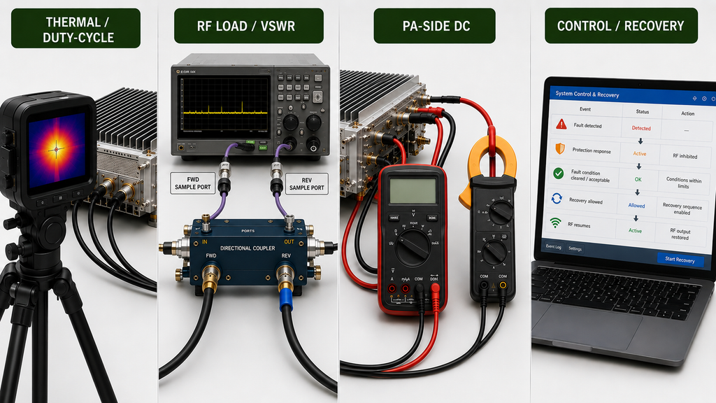
| Decision Branch | What You May Observe | Boundary to Verify First | Decision Stop |
|---|---|---|---|
| Thermal / duty-cycle stress | Output changes after longer operation, temperature rises, protection appears after time | Required duty cycle, cooling condition, thermal state, RF load | Do not call it a thermal root cause until the other relevant boundaries are controlled |
| RF-load / VSWR stress | Reflected power rises, VSWR alarm appears, output backs off or stops | Controlled PA load versus installed RF path | Do not blame the PA if the abnormal condition appears only after the installed RF path is connected |
| DC / electrical stress | Voltage changes, current changes, output becomes unstable, restart occurs | Relevant PA-side DC condition under RF load | Do not assume the PA received the required DC condition from the supply rating alone |
| Control / recovery path | Repeated trips, premature RF enable, repeated restart, unexplained mute or shutdown | Controller command sequence versus actual PA and fault state | Do not treat repeated recovery as proof of hardware failure until the original stress condition is isolated |
Thermal / duty-cycle stress
A short-duration or cold-state result should not automatically be treated as proof of the required hot operating state.
If the project depends on long-duty or continuous operation, the relevant question is whether the module remains inside the required RF, electrical, thermal, and protection boundary after the operating state develops.
Temperature is an observation, not a complete root-cause diagnosis. Cooling condition, RF load, DC state, duty cycle, and the location of the temperature measurement all affect how the result should be interpreted.
RF-load / VSWR stress
A controlled RF load and an installed antenna path answer different questions.
The controlled condition can establish a module baseline. The installed system adds feeder loss, connectors, switching or protection hardware, antenna matching, and other RF-path variables.
If the PA behaves normally on the controlled load but the abnormal condition appears only after the installed RF path is connected, isolate the RF path before replacing the amplifier.
DC / electrical stress
The relevant PA-side DC condition under RF load is what the amplifier actually sees during the operating state where the problem occurs.
A nominal power-supply rating does not automatically prove that the same voltage exists at the module after cable drop, connector resistance, current demand, startup behavior, or other distribution effects are included.
Current change is also an observation rather than an automatic root-cause label. It should be interpreted together with the RF load, thermal state, DC boundary, and protection condition.
Control / recovery path
A first protection event and a repeated restart loop are not the same problem.
If the controller immediately returns the PA to an unresolved thermal, RF-load, or electrical stress condition, the same physical stress can be applied repeatedly.
The control question is therefore:
Does the recovery sequence remove or respect the original fault condition before RF operation resumes?
The detailed command timing or state-machine test belongs in the relevant control or protection procedure. For burnout prevention, the important decision is whether control behavior is extending or repeating an already identified stress condition.
3. What Must Protection Behavior Prove Before Integration?
A datasheet statement such as “thermal protection,” “VSWR protection,” or “current protection” is not enough by itself to prove that burnout risk is controlled.
For the specific stress condition that matters to the project, the buyer should be able to answer five questions:
- Detection: What abnormal condition is recognized?
- Response: What documented action does the module take?
- Visibility: What status can the controller or operator observe?
- Recovery: Under what condition can normal operation resume?
- Evidence: Has that behavior been demonstrated at the required operating boundary?
The response is design-dependent.
A module may provide warning, output reduction, RF disable, shutdown, latch, automatic recovery, or another documented behavior. Do not assume every product supports the same sequence.
The current decision is not to reconstruct the complete RF PA protection state machine; it is to determine whether the protection behavior required by the project is defined and supported by evidence.
Decision Stop:
If the applicable trigger, response, visibility, recovery rule, or test boundary is missing, treat the protection claim as incomplete rather than assuming how the PA behaves.
4. How to Separate a PA Fault From a System-Boundary Problem
Burnout diagnosis becomes more reliable when the buyer compares boundaries rather than reacting to one symptom.
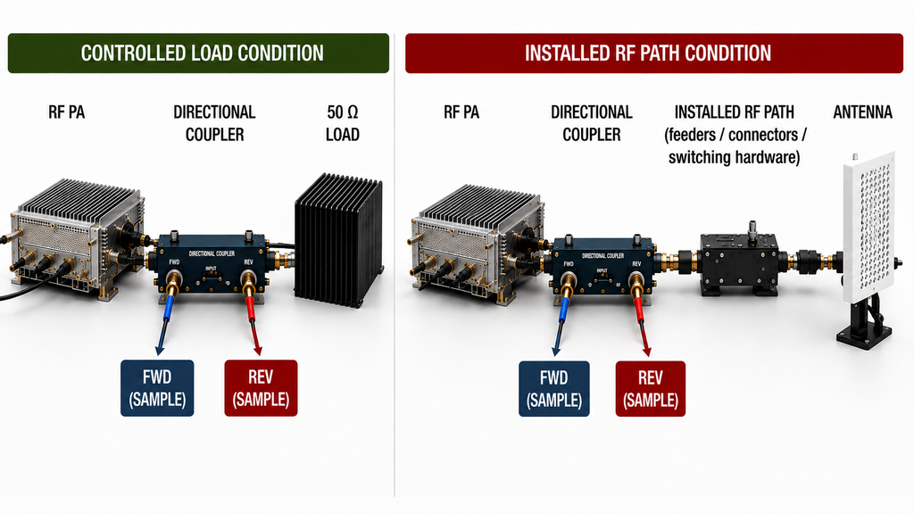
Controlled RF load vs installed RF path
If the module behaves normally on a controlled RF load but reflected power, output back-off, or shutdown appears only after the installed RF path is connected, the RF path should be isolated before the PA is classified as defective.
Decision Stop:
A controlled-load pass does not prove that the installed RF path is safe, but an installed-path fault also does not automatically prove that the PA is defective.
Power-supply output vs PA-side DC condition
A supply may show an acceptable voltage while the PA sees a different condition during RF operation.
The relevant comparison is between the required DC boundary and the voltage/current condition that actually exists at the PA under the operating state where the problem occurs.
Decision Stop:
If the PA-side DC condition under RF load has not been verified, do not conclude that the amplifier received the required electrical boundary.
Fault event vs recovery sequence
When a protection event is followed by repeated restart or re-enable behavior, separate the original fault from the recovery action.
Use the sequence:
Stress Condition → PA Response → Controller Status → Recovery Action → Next Operating State
If the next operating state simply recreates the same unresolved stress, the control path is increasing exposure rather than solving the root problem.
The detailed diagnosis of each RF-path, DC, or control interface belongs in its specialist procedure. This page only needs to establish which boundary must be isolated before a burnout conclusion is justified.
5. What Evidence Is Enough to Call the Burnout Risk Controlled?
Evidence should match:
the risk being evaluated, the operating condition under which it was evaluated, and the scope the evidence legitimately supports.
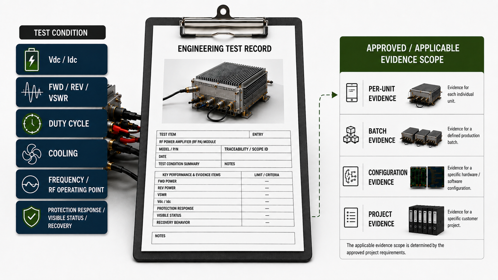
Depending on the project requirement, relevant evidence may include:
- required frequency and RF operating point;
- duty cycle or operating duration;
- cooling and thermal condition;
- Vdc and Idc at the relevant electrical boundary;
- RF load condition;
- FWD / REV / VSWR information when reflected-power behavior is relevant;
- applicable warning, output-reduction, RF-disable, shutdown, or other protection response;
- controller-visible status where required;
- recovery behavior;
- applicable hardware, firmware, or configuration state;
- the traceability required by the approved RFQ or acceptance plan.
Evidence scope must be stated rather than assumed.
Depending on the approved requirement, evidence may apply at:
- per-unit level
- batch level
- configuration level
- project level
A serial-number-linked test report can support the result for the unit it identifies. It should not automatically be expanded into a batch-level claim unless the approved evidence structure supports that broader conclusion.
Likewise, an approved batch-, configuration-, or project-level evidence plan should not automatically be rejected simply because every test was not repeated for every individual unit.
The required evidence scope comes from the approved RFQ or acceptance plan.
Three evidence rules
Rule 1 — Claim strength must not exceed the test boundary.
Evidence from one load, duty cycle, thermal state, or DC condition should not be used as proof of another untested operating condition.
Rule 2 — Observation is not the same as root cause.
Temperature rise, reflected power, current change, alarm, shutdown, or restart can support diagnosis, but each still requires the relevant boundary to be isolated.
Rule 3 — Traceability limits what the evidence can prove.
The record should identify the unit, batch, configuration, or project scope required by the approved evidence plan.
Decision Stop:
If the operating condition or evidence scope is unclear, do not convert the supplier claim into a final conclusion that the burnout risk is controlled.
6. Burnout Risk Decision Checklist Before RFQ or Integration
A useful buyer checklist connects the observed risk to the boundary, evidence, and decision it can actually support.
| Decision Branch | What You May Observe | Boundary to Verify First | Evidence Needed | Buyer Decision |
|---|---|---|---|---|
| Thermal / duty-cycle stress | Output change after time, temperature change, protection event | Required duty cycle, cooling condition, thermal state, RF load | Hot-state RF behavior plus relevant temperature, DC, load, and protection status | Risk is supported as controlled only for the documented operating state |
| RF-load / VSWR stress | REV increase, VSWR alarm, output back-off, shutdown | Controlled PA load versus installed RF path | FWD / REV / VSWR plus defined RF-load condition | Isolate the RF path before assigning a PA fault |
| DC / electrical stress | Voltage change, current change, unstable output, restart | Relevant PA-side electrical condition under RF load | Vdc / Idc and applicable operating-state record | Do not assign the fault to the PA until the electrical boundary is verified |
| Control / recovery path | Premature enable, repeated restart, mute, repeated fault state | Controller sequence versus PA protection state | Command / status / recovery sequence | Confirm that recovery does not repeatedly reapply the unresolved physical stress |
If the required operating boundary or evidence is missing for any branch, the decision is not automatically pass or fail.
The correct status is:
Cannot conclude yet.
What Buyers Should Define Before RFQ
Before comparing modules or approving an integration boundary, define:
- required frequency range or operating points;
- target RF output and relevant measurement boundary;
- required duty cycle;
- cooling condition;
- DC input and relevant PA-side electrical boundary;
- expected antenna path or load / VSWR condition;
- enable, mute, reset, and recovery requirements;
- protection functions relevant to the project;
- alarm or status visibility required by the controller;
- evidence scope required for engineering review or acceptance.
A supplier statement such as “200 W,” “28 V,” “thermal protection,” or “VSWR protection” may describe part of the module. It does not by itself define how the module behaves when the project operates outside the normal boundary.
The purpose of the RFQ is therefore not to collect the longest protection-feature list. It is to define the operating boundaries that must remain controlled before the PA is exposed to them during integration.
Conclusion
Drone jammer module burnout is best prevented by controlling the physical stress boundary before hardware failure occurs.
First identify whether the direct stress is thermal / duty-cycle, RF-load / VSWR, or DC / electrical. Then determine whether control or restart behavior is repeatedly exposing the PA to that unresolved condition.
Next verify the required protection response, controller visibility, recovery behavior, and evidence scope.
Alarm visibility and S/N or batch traceability are not physical burnout causes. They determine whether the event can be diagnosed and whether the available evidence legitimately supports the buyer’s conclusion.
A clean bench result is also not enough when the real installation uses a different thermal state, antenna path, PA-side DC condition, or operating rhythm.
If the relevant stress boundary has not been isolated, or if the protection behavior and evidence scope remain unclear, the correct decision is cannot conclude yet.
If you want RF SKYPOWER to review a drone jammer RF PA requirement, provide the required frequency range, target RF output, duty cycle, cooling condition, DC input, antenna-path or VSWR boundary, control and recovery requirements, alarm / status needs, and required evidence scope. These inputs can be used for an engineering review of available or custom RF PA options; final suitability still depends on the agreed project conditions and verification evidence.
FAQ
Can protection circuits prevent every drone jammer module burnout?
No. Protection can reduce hardware risk under the conditions it is designed and validated to handle, but it does not automatically correct an unsafe RF load, inadequate cooling, incorrect DC boundary, or a recovery sequence that repeatedly returns the PA to the same unresolved stress condition.
Can a module pass a controlled-load test and still face burnout risk after installation?
Yes. A controlled-load test establishes a module baseline under a known RF condition. The installed RF path introduces additional feeder, connector, switching, protection-device, and antenna conditions. If the abnormal behavior appears only after installation, isolate that path before blaming the PA.
How do I know whether the primary problem is thermal, RF-load, DC, or a control/restart sequence?
Identify the condition that changes when the symptom appears. Compare cold and required operating state, controlled and installed RF load, supply reading and PA-side DC condition, then determine whether the control sequence repeatedly returns the PA to an unresolved physical stress condition.
What evidence should buyers request before RFQ or integration?
Request evidence that matches the actual burnout-risk boundary. Depending on the project, this may include thermal / duty-cycle behavior, Vdc / Idc, RF-load or FWD / REV / VSWR information, protection response, alarm or status visibility, recovery behavior, and traceability at the required per-unit, batch, configuration, or project scope.