










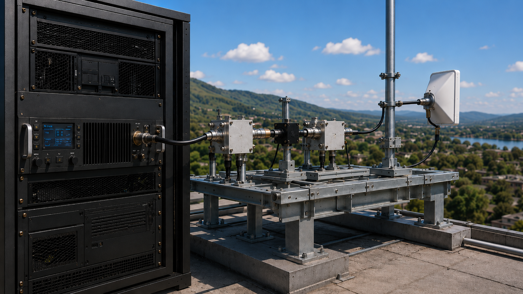
RF amplifier range is not decided by wattage alone. A higher-power RF amplifier can increase the transmit-side power available to a link, but it cannot by itself prove a longer real-world operating range.
The result changes after RF output leaves the defined PA reference plane. Feeder loss, connectors, switching hardware, antenna matching, antenna gain and pattern, propagation, interference, and receiver-side requirements all affect how much useful margin remains in the complete system.
The same caution applies to “cleaner signal.” A high RF power reading does not prove good signal quality. The applicable metric depends on the actual waveform, measurement boundary, source quality, and system requirement.
The practical buyer question is therefore not simply:
“How many watts does the amplifier produce?”
It is:
“What does the measured PA output prove, what reaches the next RF boundary, and what additional evidence is required before we conclude that range or signal quality has improved?”
1. What Can an RF Amplifier Actually Change About Range?
An RF power amplifier can increase the transmit-side RF power available to the system.
If the additional output is produced within the required frequency, waveform, load, DC, thermal, and linearity conditions, it can contribute additional link margin.
That contribution is real, but it is only one input to the complete range decision.
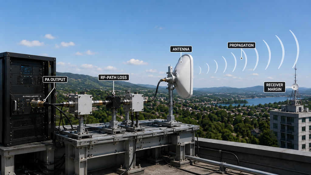
Actual usable range may also depend on:
- downstream RF-path loss;
- antenna gain and radiation pattern;
- antenna placement and orientation;
- propagation conditions;
- receiver sensitivity and noise environment;
- interference;
- waveform requirements;
- the minimum usable performance required at the receiver or other final system boundary.
Two systems using amplifiers with the same rated output power can therefore produce different usable results.
Likewise, increasing PA output does not guarantee a proportional increase in operating distance. The additional transmit-side margin still has to survive the installed RF path and remain usable at the final system boundary.
The buyer-side rule is:
Higher compliant PA output can contribute more link margin. It does not independently prove a specific real-world distance.
A link budget can support an engineering estimate when its assumptions are defined. A field or system test can support the tested configuration and environment. Neither should be converted into a universal distance guarantee.
2. Separate PA Output, Antenna-Input Power, and Receiver Link Margin
Range conclusions become unreliable when measurements taken at different RF output reference planes are treated as though they represent the same quantity.
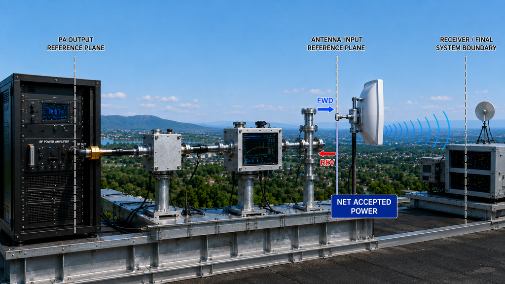
PA output reference plane
This is the RF output attributed to the amplifier at a defined measurement plane.
The result should be tied to the relevant conditions, including:
- frequency;
- actual RF input drive;
- waveform;
- load;
- DC supply;
- thermal state;
- duty cycle;
- measurement and correction method.
A PA-port result can support a PA-level performance decision.
It does not automatically equal the RF power available at the antenna input.
Installed RF-path boundary
After the PA, the RF signal may pass through cables, connectors, filters, switches, combiners, protection hardware, and other downstream components.
Characterized insertion loss in those components reduces downstream forward power.
Mismatch is different.
A mismatched load can create reflected power and change the operating condition seen by the PA. Depending on the amplifier and protection design, forward output may also change.
For this reason:
Forward power at the antenna-input reference plane and net power accepted by a mismatched antenna are not automatically the same quantity.
If the engineering decision requires net accepted power rather than forward power alone, the relevant forward and reflected measurements must refer to a compatible reference plane, frequency, measurement condition, and power definition.
Do not treat VSWR as though it were simply another cable-loss value that can always be subtracted from PA output.
Antenna and system boundary
Power measured at the antenna-input reference plane still does not prove a universal range.
Antenna gain, radiation pattern, polarization, installation geometry, surrounding structures, and propagation affect how RF energy is distributed.
Receiver or final system boundary
For a communication link, usable range ultimately depends on whether sufficient margin remains at the receiver under the required operating condition.
That decision may require:
- receiver sensitivity;
- noise and interference assumptions;
- required SNR or demodulation performance;
- antenna information;
- propagation assumptions;
- other application-specific system criteria.
The boundary rule is simple:
Do not allow a PA-port measurement to silently become a system-level range result.
3. When Does More RF Power Help—and When Does It Stop Helping?
More PA output helps only when the additional power remains usable at the required downstream and system boundaries.
Four conditions commonly limit the expected benefit.
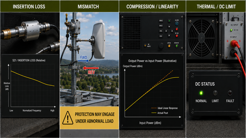
Downstream insertion loss
Cable, connector, filter, switching, and other passive losses can reduce the forward RF power available farther downstream.
The buyer should therefore keep the PA reference plane and the required downstream reference plane separate.
Load mismatch and protection behavior
Mismatch changes the RF load condition and may create reflected power.
Depending on the PA design, an abnormal load may also trigger output reduction or another documented protection response.
This is different from insertion loss and should be evaluated separately.
Compression and linearity
Increasing drive does not always create proportional usable output.
As the PA approaches compression, nonlinear behavior may become more significant. Whether that matters depends on the actual waveform and the applicable signal-quality requirement.
Thermal, DC, or system limitations
A short bench result may not represent stabilized operation, and a nominal supply condition may not represent the electrical boundary actually present at the PA during RF operation.
Even when the PA itself remains compliant, another system limitation—such as downstream loss, unsuitable antenna behavior, receiver limitations, interference, or propagation—may become dominant.
This is why selecting the highest wattage is not the same as optimizing usable range.
4. What Does “Clean Signal” Mean for the Actual Waveform?
“Clean signal” is not one universal RF PA specification.
The correct evidence depends on the waveform and on what the system needs to preserve.
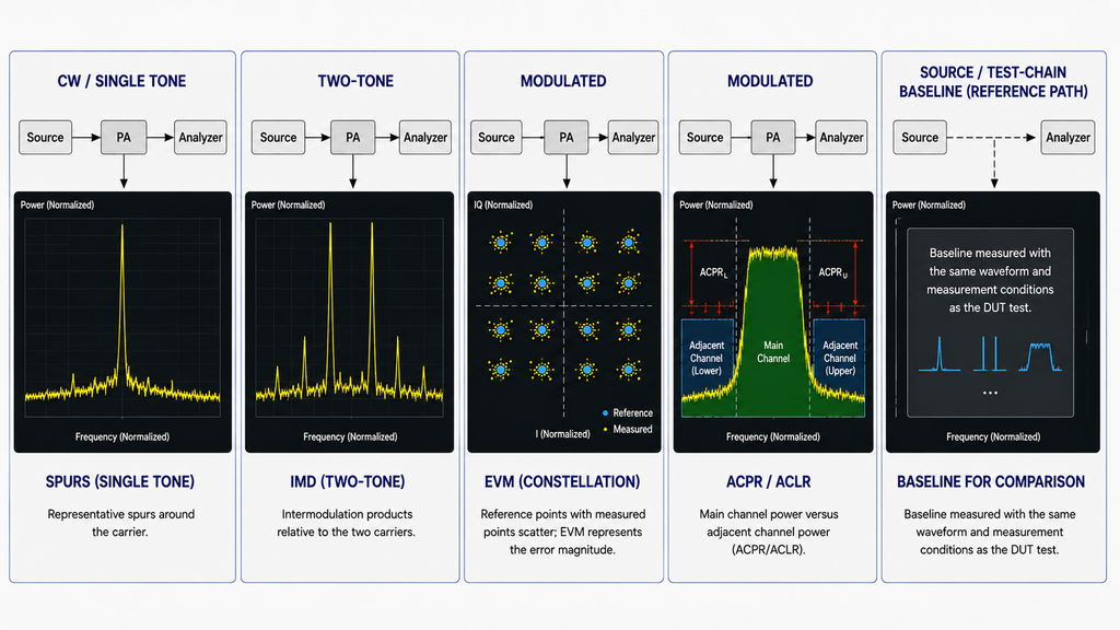
CW or single-tone operation
Relevant evidence may include:
- output power;
- gain;
- harmonics;
- spurious behavior;
- other single-tone requirements defined by the application.
EVM or ACPR should not be added mechanically when they are not meaningful for the actual waveform.
Two-tone testing
A two-tone test can evaluate nonlinear behavior such as intermodulation under a defined operating condition.
It answers a different question from a modulated-waveform test.
Modulated waveform
Depending on the system requirement, applicable measurements may include:
- EVM;
- ACPR / ACLR;
- occupied bandwidth;
- spectral regrowth;
- other waveform-specific linearity or spectral metrics.
The applicable metric and limit must come from the actual requirement rather than from a generic checklist.
Where the measurement is sensitive to the signal source or test chain, preserve an appropriate source and measurement-chain baseline. This helps distinguish PA-added degradation from distortion already present in the stimulus or measurement setup.
Receiver-side SNR
Receiver SNR is a system-level result.
It can be influenced by transmit power, RF-path loss, antenna behavior, propagation, receiver noise, interference, and other system effects.
It should not be presented as though it were an independent PA-output specification.
The decision rule is:
Use the metric that matches the waveform, reference plane, and system requirement actually being evaluated.
5. What Evidence Supports a Range and Signal-Quality Decision?
The strongest evidence structure keeps every conclusion attached to the boundary and condition that produced it.
| Buyer Claim | Required Boundary | Evidence Needed | What It Does NOT Prove |
|---|---|---|---|
| Higher PA output | Defined PA output reference plane | Condition-defined RF output with frequency, actual input drive, waveform, load, DC, thermal state, and applicable correction method | Forward power available at the antenna input |
| More forward RF power is available at the antenna-input reference plane | Defined installed RF path / antenna-input reference plane | Direct downstream measurement, or PA output plus characterized insertion loss under the defined RF-path condition; include same-plane FWD/REV evidence when accepted power under mismatch matters | Net accepted antenna power unless that quantity is separately established; radiated range |
| Expected usable range | Receiver / final system boundary | Defined link-budget inputs, antenna data, receiver requirements, propagation assumptions, and other relevant system conditions | Tested operating distance |
| Tested operating range | Complete tested system and environment | Field or system evidence for the documented configuration, environment, waveform, and acceptance condition | Universal distance under different sites, environments, or configurations |
| Cleaner signal | Defined waveform and measurement reference plane | Applicable EVM, ACPR/ACLR, IMD, harmonic, spurious, or other waveform-specific evidence, with source/test-chain baseline where relevant | Performance for another waveform, operating state, or measurement boundary |
| Full-band usable performance | Required frequency points or defined band | Condition-aligned output and applicable signal-quality evidence across the required frequency scope | Untested frequencies or operating states |
The core evidence rule is:
Each result should remain attached to the boundary, condition, and evidence scope that produced it.
A PA report can support PA-level behavior.
An installed-path measurement can support RF behavior at that installed boundary.
A link budget can support an engineering estimate when its assumptions are defined.
A field result can support the documented test configuration and environment.
None of these should silently be expanded into a stronger claim than the evidence supports.
Comparison eligibility
Before ranking two supplier reports, align the critical conditions, including:
- frequency;
- actual RF input drive;
- waveform;
- output reference plane;
- raw versus corrected output;
- load condition;
- DC condition;
- thermal state;
- duty cycle;
- applicable signal-quality metric.
If these conditions cannot be aligned, the reports may still support initial screening, but they are not directly comparable yet.
When two results are close to an acceptance threshold or close to each other, calibration status and applicable measurement uncertainty should also be considered before treating a small numerical difference as an engineering advantage.
Frequency scope
A center-frequency result does not automatically prove full-band behavior.
If the project depends on multiple frequencies or a defined operating band, the evidence should cover the frequency points required by the project.
The rule is:
Do not extend a measured result beyond the frequency scope that was actually demonstrated.
6. What Buyers Should Define Before RFQ
For this page’s specific range-and-signal-quality decision, the buyer should make six boundaries clear before comparing supplier claims:
- Required PA output and its reference plane
- Installed RF-path / downstream measurement boundary
- Receiver or final system boundary used for the range decision
- Actual waveform or modulation condition
- Signal-quality metric required by that waveform and application
- Evidence required to support the range or signal-quality conclusion
Other conditions—such as frequency, actual input drive, DC, thermal state, duty cycle, and load—still matter because they determine whether two PA results are comparable. They should be included in the applicable test evidence rather than turning this page into a complete RF PA selection checklist.
Do not ask only:
“Can you supply a 100 W amplifier?”
Ask:
“Where is that 100 W defined, under which conditions, and what does it actually prove at the next system boundary?”
Likewise, do not ask only:
“Will this improve range?”
Ask whether the available evidence supports an engineering estimate, a tested system result, or only a PA-level output claim.
Conclusion
More RF amplifier power can improve transmit-side link margin, but wattage alone does not prove longer usable range or cleaner signal quality.
Keep each conclusion attached to the correct boundary:
PA output → installed RF-path delivery → antenna/system boundary → receiver or final system margin.
At the antenna-input boundary, also distinguish forward power from net power accepted under mismatch when that distinction matters to the engineering decision.
Keep the physical mechanisms separate as well. Insertion loss reduces downstream forward power. Mismatch changes the load condition and can create reflected power. Protection may change PA behavior under that load. Compression or insufficient linearity margin can degrade the required waveform.
For range, distinguish an engineering estimate from a tested operating result. A link budget supports the former when its assumptions are defined; field validation supports the documented tested configuration and environment.
For signal quality, use the metric that matches the actual waveform and preserve source or measurement-chain baseline information when needed to attribute degradation correctly.
If the reference plane, waveform, operating condition, system assumptions, or evidence scope is missing, do not turn a PA power number into a stronger range or signal-quality conclusion.
The correct decision is:
The available evidence is not sufficient yet.
If you want RF SKYPOWER to review an RF PA requirement, provide the required frequency points, target output and reference plane, available input drive, waveform, downstream RF-path boundary, final system requirement, and required signal-quality evidence. These inputs can support an engineering review of available or custom RF PA options; final project suitability still depends on the complete system conditions and verification evidence.
FAQ
Does a higher-power RF amplifier always increase range?
No. Higher compliant PA output can contribute additional transmit-side link margin, but actual range also depends on the installed RF path, antenna, propagation, interference, and receiver or final system requirement. PA wattage alone cannot prove a specific distance.
Is PA output power the same as the power available at the antenna?
Not necessarily. PA output is tied to a PA reference plane. Downstream insertion loss can reduce forward power before the antenna. Under mismatch, forward power at the antenna-input reference plane and net power accepted by the antenna are also not automatically the same quantity.
Does a link budget prove real-world RF range?
No. A link budget supports an engineering estimate when its inputs and assumptions are defined. A tested operating range requires field or system evidence under the documented configuration and environment, and that result should not be generalized beyond the conditions actually tested.
Does higher RF power automatically mean a cleaner signal?
No. Signal quality depends on the waveform, PA operating point, reference plane, and applicable metric. Source quality and measurement-chain contribution may also need to be separated from PA-added degradation.
What evidence should buyers compare between RF amplifier suppliers?
Compare condition-aligned evidence for output reference plane, frequency, actual input drive, waveform, load, DC and thermal state, duty cycle, and the applicable signal-quality metric. When results are close, calibration status and measurement uncertainty may also affect whether a small numerical difference is meaningful.