










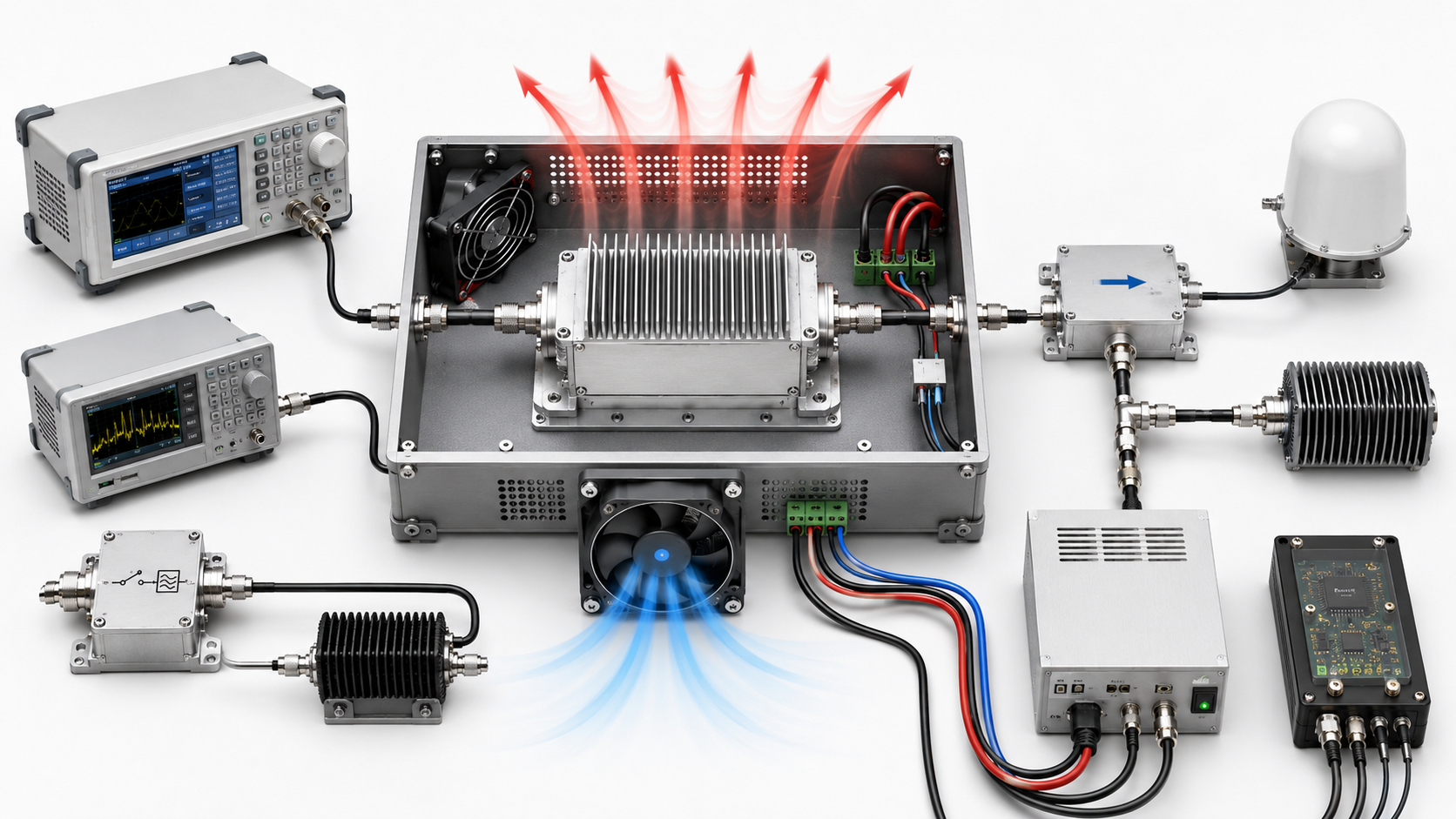
Fix one application requirement set before comparing RF power amplifier quotes. Similar frequency ranges and wattage labels are only useful when the quoted values refer to sufficiently aligned reference planes, input drive, waveform, duty cycle, thermal and DC conditions, load state, and evidence scope.
If those conditions differ, hold the affected part of the ranking and request the missing evidence. Do not turn an unknown condition into an assumed margin, and do not reject a candidate from results that were generated under a different decision boundary.
When the application requirement itself is still incomplete, define the RF PA requirement and RFQ boundary before comparing suppliers. Once that baseline is fixed, every candidate should be tested against the same engineering question: does the evidence show that this amplifier can meet the required result under the required conditions?
Fix One Comparison Baseline Before You Review Supplier Quotes
A supplier comparison needs one baseline that does not change from quote to quote. Otherwise, the buyer can end up comparing each candidate against a different version of the project requirement.
The baseline should contain only the conditions that can change candidate eligibility or the meaning of the quoted evidence:
- required frequency points or continuous span;
- required RF output, including whether it is minimum, average, peak, CW, or another defined quantity;
- the physical reference plane where that output must exist;
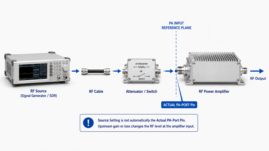
- RF input available at the PA input reference plane;
- waveform, bandwidth, duty cycle, and any required linearity boundary;
- thermal state, cooling condition, module-side DC voltage, and relevant load condition;
- mechanical, RF-interface, control, monitoring, and protection constraints that can disqualify a candidate;
- the evidence scope needed for the decision, including model, revision, sample, unit, or delivered-S/N identity where applicable.
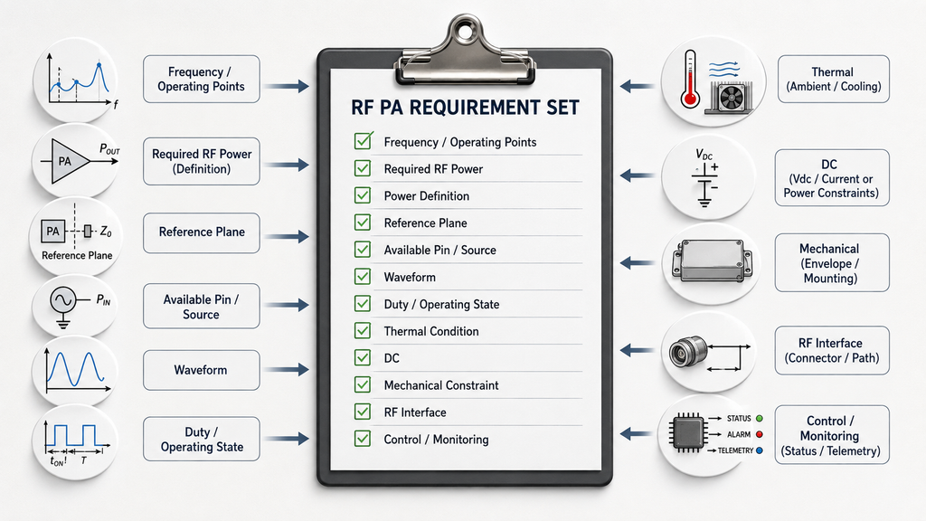
Use this as the comparison baseline; the full RFQ-development work stays upstream. If a field is still genuinely unknown, keep it open and identify whether the missing value blocks the whole shortlist or only one comparison dimension.
Supplier responses should not redefine the requirement. A quote can expose an assumption that needs clarification, but the project should decide whether to change its baseline deliberately rather than silently adapting it to whichever product looks easiest to buy.
Normalize Frequency Scope, RF Output, and Reference Plane
Start by checking whether every quote is answering the same frequency and RF-output question.
A listed range such as 300–2700 MHz is not equivalent to evidence that the required output is available at every project-critical point inside that range. For a fixed-frequency project, evidence at the required point may be sufficient. For several operating points, compare those points explicitly. For continuous coverage, the supplier evidence should support the required span and relevant band edges.
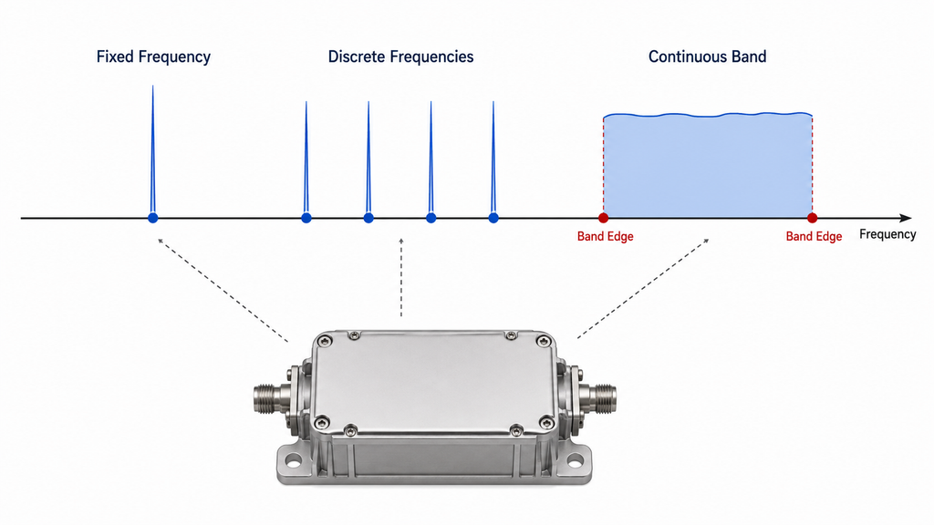
Do not reward a wider frequency label unless the project needs that additional coverage. Frequency architecture and range selection belong to their own engineering decision; the quote comparison only asks whether each candidate supports the already-defined requirement.
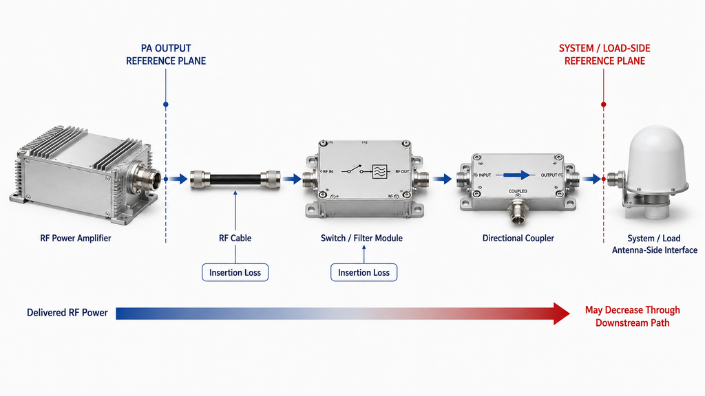
RF output also needs one definition and one reference plane. A quote stating “100 W” at the PA output connector cannot be compared directly with another quote stating 100 W after a filter, switch, feeder, or other downstream path. Rated output, typical measured output, and guaranteed minimum output are also different evidence classes.
For each candidate, record:
Power definition + frequency condition + reference plane + evidence status
If the system requirement is defined downstream of the PA and the PA-port requirement still has to be derived from installed loss, complete the usable RF output power review before ranking the quotes.
A candidate can remain in the review while one output condition is unresolved, but the unresolved value should not be converted into a comparative advantage or disadvantage.
Align Pin, Waveform, Duty Cycle, Thermal State, and DC Conditions
The next comparison layer is the operating condition that produced the quoted RF result.
Actual Pin and gain condition
The signal-source setting is not automatically the RF input at the PA connector. Cables, attenuators, splitters, switches, filters, connectors, and driver stages can change the level reaching the amplifier.
A valid comparison should therefore identify the actual or properly derived Pin at the PA input reference plane. If Supplier A reaches the target output with a lower Pin than Supplier B, that difference may matter to the system architecture, but only when both results use compatible frequency, waveform, thermal, DC, and load conditions.
A nominal gain value by itself does not establish the gain available at the required operating point.
Waveform and duty cycle
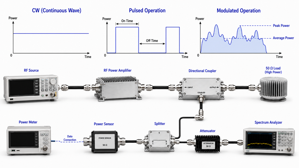
CW, pulsed, modulated, multi-tone, and multi-carrier results should not be treated as interchangeable power evidence. Peak, average, composite, and peak-envelope values can describe different signal conditions.
Record the waveform and duty condition next to the power result. Where linearity or backoff is part of the project requirement, compare compliant usable output rather than the highest output the hardware can momentarily produce.
Thermal and DC state
A cold startup result and a thermally stabilized result answer different questions. Likewise, a nominal power-supply setting is not the same as the voltage present at the PA terminals while the amplifier is delivering RF power.
When sustained operation matters, compare candidates at an appropriate stabilized thermal condition and record the relevant cooling boundary. For the DC condition, identify the module-side voltage and current state that applies to the RF result.
Suppliers can use different laboratory equipment, but the test boundaries still need enough alignment for the results to answer the same project decision.
Compare Integration Limits Without Mixing Module and System Responsibility
A candidate can meet the headline RF requirement and still be unsuitable for integration. Compare the limits that can change the architecture or create a redesign:
- mechanical envelope, mounting, connector orientation, and cable-clearance requirements;
- RF connector and downstream-path compatibility;
- cooling interface and installation responsibility;
- DC input range, current demand, and wiring boundary;
- control interface, enable behavior, status feedback, and required monitoring;
- protection behavior that can change usable output or availability under the project load condition.
Keep module behavior separate from system behavior. A PA supplier can document the module output, interface, internal protection response, and required cooling boundary. The system integrator may still own feeder loss, antenna match, cabinet airflow, external interlocks, DC distribution, or supervisory logic.
For C-UAS projects whose frequency architecture, channel operation, control, protection, or system responsibility is still unresolved, return to the broader C-UAS RF PA selection workflow before finalizing the shortlist.
Integration differences may leave both candidates technically viable while changing installation cost, required support hardware, or the engineering work left before approval. Keep those consequences visible instead of collapsing them into one undocumented “better product” score.
Decide Whether the Evidence Is Comparable Before You Rank Candidates
The comparison should now answer a narrower question: which claims can be placed side by side without changing their technical meaning?
Datasheets are useful for screening, but a value can be technically correct and still be unusable for comparison when its test condition is missing. If a rating is unclear, use the RF power amplifier datasheet review to identify which condition or supporting evidence must be requested.
Use three practical comparison statuses:
- Comparable — the decision-relevant definitions, reference planes, operating conditions, and evidence scope are sufficiently aligned for the specific comparison being made.
- Partially comparable — some dimensions are aligned, but one or more unresolved conditions limit what can be ranked.
- Hold: missing evidence — a decision-critical condition or evidence item is absent or materially different, so ranking that dimension would create a false conclusion.
A hold means the available evidence cannot yet support the proposed ranking.
RF PA Quote Comparison Matrix
Use one row per supplier candidate. Record only what the quote, datasheet, or supporting evidence actually states; do not fill missing fields with typical assumptions.
Compare one supplier candidate per row
Keep the same requirement baseline · Scroll horizontally to review all fields →
| Candidate | Frequency / scope | Pout + reference plane | Actual Pin / gain condition | Waveform / duty | Thermal / DC / load state | Evidence scope / revision | Comparison status | Missing evidence / next action |
|---|---|---|---|---|---|---|---|---|
| One row per supplier candidate | Record required points/span and what the evidence covers | Record power definition, status, and physical reference plane | Record Pin at the PA input plane and the applicable gain/drive condition | Record signal type, bandwidth/backoff where relevant, and duty condition | Record thermal state, module-side Vdc, cooling, and load boundary that apply | Record model/revision and whether evidence is datasheet, characterization, sample, unit, or other defined scope | Comparable / Partially comparable / Hold: missing evidence | State the exact condition, test result, or document needed before the affected ranking can proceed |
Do not turn the table into a weighted score that averages away missing engineering conditions. One decisive mismatch can matter more than several aligned secondary fields.
The same rule applies to evidence scope. A representative sample result can support the stated sample or design conclusion. It should not be presented as proof for every delivered unit unless the agreed evidence plan supports that use.
Build the Qualified Shortlist and Request Only the Missing Evidence
A candidate belongs on the qualified shortlist when the available evidence supports the project requirement at the level needed for the current decision. The shortlist can be built before every production-acceptance record exists, but it cannot depend on unresolved assumptions that could reverse the selection.
For each candidate, close the comparison with four items:
- What is already supported? Identify the frequency, RF output, drive, operating, integration, and evidence dimensions that are sufficiently aligned.
- What remains unresolved? Name the exact missing condition or evidence item.
- Does the missing item block the shortlist? Separate a decision-critical gap from an enhancement that can wait until later verification.
- What should happen next? Request the missing evidence, retain the candidate conditionally, or remove it because a defined project requirement is not met.
Do not ask every supplier for a generic “full test report” when only one missing condition blocks the decision. A precise request is easier to verify and produces cleaner supplier comparisons.
Examples of precise requests include:
- output at the required frequency and stated PA output reference plane;
- actual Pin required to reach the quoted operating point;
- hot-state output after the agreed operating duration;
- module-side voltage and current during the RF result;
- waveform-specific compliant output instead of a CW-only rating;
- load or protection behavior under the agreed mismatch condition;
- the document revision, sample identity, or unit identity that defines the evidence scope.
Once the engineering shortlist is qualified, the RF power amplifier module range can be used as a product-discovery route. That route helps identify candidate families for further review; it does not establish that any listed model meets the project requirement.
Conclusion
Judge an RF power amplifier quote by whether its claims can be interpreted against the same application baseline and whether its evidence supports the required result under sufficiently aligned conditions.
The most common comparison error is to treat matching headline values as proof that two amplifiers are interchangeable. Differences in reference plane, actual Pin, waveform, duty cycle, thermal state, module-side voltage, load condition, test method, or evidence scope can change the meaning of the numbers.
Before ranking the final candidates, freeze the comparison baseline, mark each quote as comparable, partially comparable, or held for missing evidence, and request the specific evidence that prevents a clean decision. Advance only the candidates that remain supported after those conditions are resolved.
For project-specific review, send RF SKYPOWER the fixed requirement baseline, supplier comparison matrix, unresolved evidence list, and qualified shortlist. Contact RF SKYPOWER Engineering Team for a condition-matched review before a model recommendation or quotation is treated as final.