










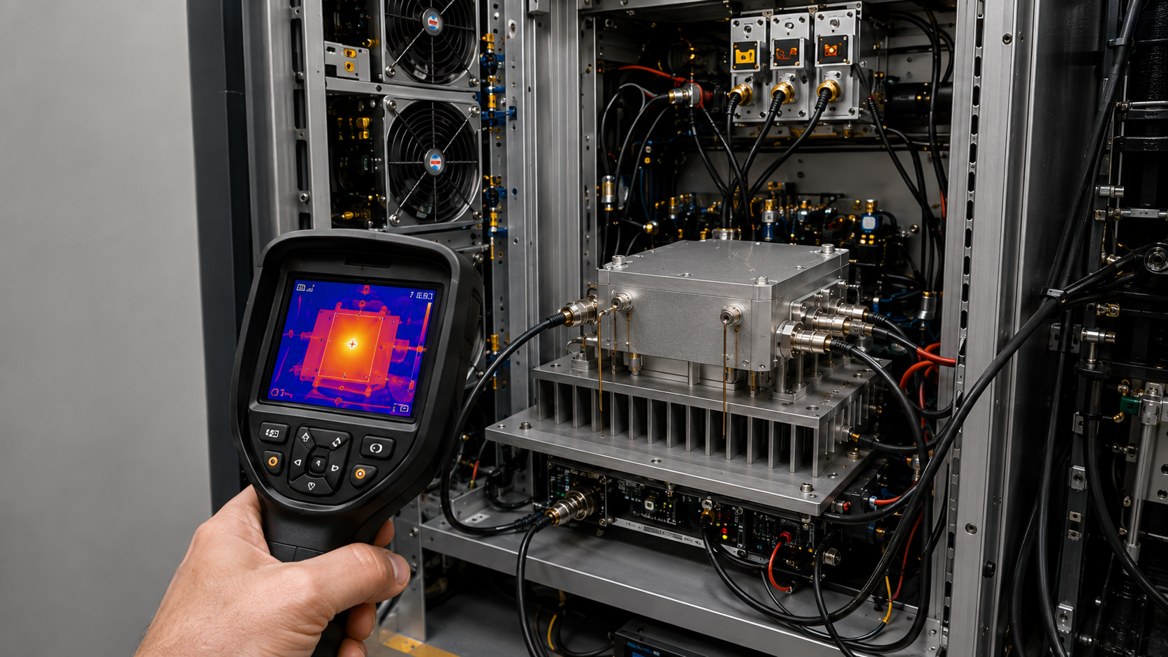
RF power amplifier thermal management is not decided by heatsink size alone. A heatsink can meet a calculated °C/W target while the installed PA still has insufficient thermal margin because the heat load, temperature reference, cooling condition, duty profile, or installation environment was defined incorrectly.
Start with the actual RF/DC operating point. Determine how much heat crosses the defined thermal boundary, identify the physical temperature point that must be controlled, and define the worst-case air, coolant, or other cooling reference seen by the installed PA.
The goal is to establish two engineering outputs: an RF PA Thermal Integration Budget and a Thermal Operating Envelope. Detailed heat-load calculation, heatsink implementation, cabinet-airflow execution, and application-specific acceptance remain separate specialist decisions.
Only after these boundaries are aligned can you judge whether the proposed cooling method is adequate.
1. What Must Be Defined Before You Calculate RF PA Thermal Management?
Before calculating heat or choosing a cooling method, build a Thermal Design Input Set for the operating state the system must actually support.
Define:
- operating frequency or relevant frequency points;
- required
Poutand its RF reference plane; Pinwhere it materially affects the energy balance;- module-terminal
VdcandIdc; - waveform;
- duty cycle;
- required operating duration;
- mounting and cooling condition;
- maximum ambient, inlet-air, coolant, or other cooling-reference temperature;
- the physical temperature point that must be controlled;
- the applicable supplier or project temperature limit for that point.
Then separate those inputs into three boundaries.
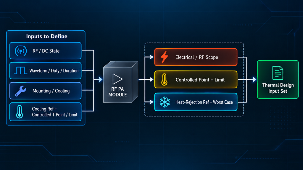
Heat-generation boundary. Define the electrical and RF boundary around the object being cooled. A final RF stage, complete PA module, and multi-channel subsystem may include different DC loads and RF transfers.
Temperature boundary. Define the physical point that must remain within its limit. Junction, case, baseplate, heatsink, cabinet air, coolant, and external ambient are different quantities.
Cooling/environment boundary. Define where heat is rejected, such as cabinet inlet air, local heatsink air, coolant at a specified point, or a cold-plate interface.
If these boundaries are mixed, a calculation can remain mathematically consistent while describing the wrong physical system.
Before proceeding, you should be able to answer:
At what boundary is heat generated, which physical temperature point must remain below which limit, and under what defined cooling condition?
2. How Much Heat Must the RF Power Amplifier Actually Remove?
RF output power is not the PA heat load.
At a defined PA-module boundary, use the energy balance only when Pdc, Pin,net, and Pout,net describe the same physical boundary and operating or averaging interval:
Pheat ≈ Pdc + Pin,net − Pout,net
For the DC input:
Pdc = Vdc × Idc
Use actual loaded module-terminal voltage and current for the relevant RF state. Do not substitute nominal supply voltage, a power-supply setpoint, or data measured under another operating condition.
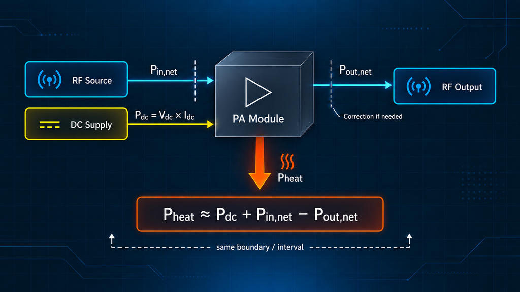
The RF terms must also describe the power crossing the chosen boundary. When mismatch materially changes net RF transfer, stop until forward/reflected power, reference planes, and measurement corrections have been reconciled. When mismatch materially changes net RF transfer, reconcile the RF boundary in the RF PA heat-load calculation from efficiency and net RF power before accepting Pheat as a cooling-design input.
Efficiency data require the same boundary discipline. Drain efficiency, PAE, module DC-to-RF efficiency, and system efficiency can describe different electrical scopes and should not be interchanged without confirming what each value includes.
For this integration decision:
Carry a heat-load value into the cooling design only after its electrical/RF boundary, reference definition, and operating interval are aligned.
Do not freeze Pheat while any of the following remains unclear:
- which efficiency or energy-balance definition is being used;
- which DC loads are included;
- where RF input and output are referenced;
- whether mismatch materially changes net RF transfer;
- whether the RF and DC data represent the same operating or averaging interval.
Until those conditions are aligned, the heat-load result is not a reliable cooling-design input.
3. How Do You Build the RF PA Thermal Path and Thermal-Resistance Budget?
Once Pheat is defined, translate it into an allowable temperature rise across a named physical thermal path.
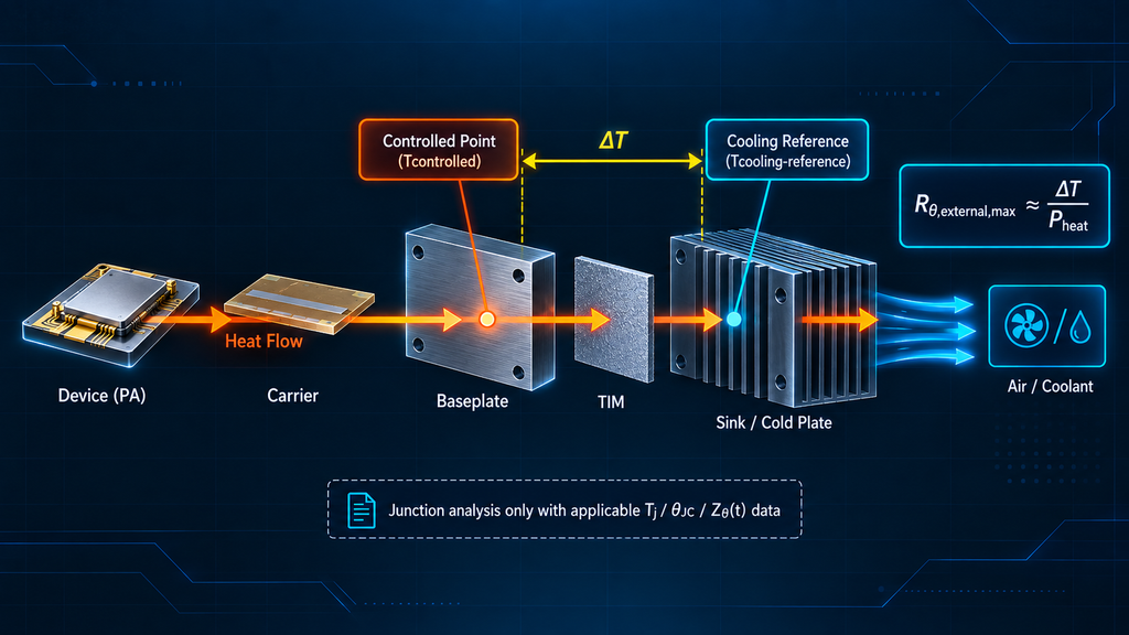
A typical path may include:
RF device/package
→ PCB, carrier, or spreader
→ module baseplate
→ TIM or mounting interface
→ heatsink or cold plate
→ cabinet air or coolant
→ final environment
The heatsink is only one element in that path. A thermal-resistance value is meaningful only when both physical endpoints are defined.
Module-Level Integration Budget
If applicable supplier or project evidence gives a clear case, baseplate, or module temperature limit:
Allowable ΔT = Tcontrolled,max − Tcooling-reference,max
For a predominantly steady-state external path between those named points:
Rθ,external,max ≈ Allowable ΔT / Pheat
The actual thermal resistance from the controlled module point to the defined cooling reference must remain at or below this value under the specified mounting and cooling condition.
An RF power amplifier heat sink rating represents only the thermal path defined by that rating; it does not replace the complete external resistance unless the endpoints and operating conditions match. If the controlled point is the module baseplate and the environmental reference is cabinet inlet air, the external path may include:
- TIM;
- mounting interface;
- heat spreading;
- heatsink or cold plate;
- airflow or coolant behavior.
A heatsink catalog rating should only be used for the physical path that rating actually defines. It should not replace a complete baseplate-to-cooling-reference resistance unless the endpoints and operating conditions genuinely match.
Once the allowable resistance is known, the remaining question is whether the real TIM, mounting, spreading path, and heatsink implementation can stay inside that budget. If TIM, mounting, heat spreading, or heatsink implementation can consume the external resistance budget, verify those interfaces against the RF PA heatsink design requirements before releasing the cooling design.
Do not calculate ΔT from room ambient when the PA is actually cooled by hotter cabinet inlet air.
Device-Level Junction Budget
Move to a junction-level calculation only when applicable device or model data support it.
The analysis may require:
- an applicable
Tjlimit; θJCor applicable transient thermal impedance;- the physical reference definition associated with that value;
- the operating conditions under which it applies.
An RF amplifier baseplate temperature limit is usable only when the supplier or project evidence clearly defines the physical reference point and applicable operating condition. First determine whether it refers to ambient, case, baseplate, junction, storage, or another condition.
If model-specific evidence is unavailable, stop at the case, baseplate, or module boundary the available evidence actually supports. Do not transfer Tj, θJC, or transient thermal parameters from another model without evidence that they apply.
RF PA Thermal Integration Budget
| Parameter | Defined Boundary / Reference | Required Input | Worst-Case Condition | Decision Use |
|---|---|---|---|---|
Pout | Defined RF output plane | Required or measured RF output | Governing frequency, load, waveform, thermal state | Defines RF power leaving the boundary |
Pdc | Powered module or subsystem boundary | Actual loaded Vdc × Idc | Highest relevant DC load at the matched RF state | Defines electrical power entering the boundary |
Pheat | Same energy boundary as Pdc, Pin,net, Pout,net | Reconciled heat-load result | Governing operating or averaging interval | Sets the cooling-design heat load |
| Temperature limit | Exact junction, case, baseplate, or module point | Applicable supplier or project limit | Highest permitted value | Sets the upper thermal boundary |
| Cooling reference | Inlet air, local air, coolant, cold plate, or defined interface | Maximum reference temperature | Worst credible installation environment | Sets the environmental end of ΔT |
| Thermal path | Controlled point to the defined cooling reference | Path elements and interface responsibilities | Final mounting and cooling configuration | Allocates the thermal-resistance budget |
| Duty / time | Actual RF operating sequence | CW duration, pulse duty, cycling, mission interval | Most demanding required state | Determines steady-state or transient relevance |
| Derating | Defined hot condition and RF reference | Allowed reduction, minimum Pout, duration | Highest acceptable derated condition | Separates normal and degraded operation |
| Protection | Defined sensor/reference and protection state | Warning, foldback, shutdown, recovery | Condition near the safety boundary | Defines protection behavior |
The equations and placeholders in this table are model-neutral engineering tools. They are not RF SKYPOWER product specifications.
4. How to Cool RF Power Amplifier Systems Under Real Installation Conditions
RF power amplifier cooling should use the worst credible air, coolant, or interface condition seen by the PA rather than room temperature by default.
A real installation may include:
- high external ambient temperature;
- hotter cabinet inlet air;
- sealed or partly ventilated enclosures;
- nearby processors, converters, or RF modules;
- several PA channels operating simultaneously;
- filters or dust loading;
- restricted vents;
- cable blockage;
- hot-air recirculation.
The thermal budget should therefore use the worst credible cooling reference that directly controls the PA thermal path.

For forced-air cooling, this may be cabinet inlet air or another defined local-air point. For liquid cooling, it may be coolant temperature at a specified location.
Multi-channel systems require particular care because one PA can change the cooling condition seen by another.
When pressure loss, recirculation, fan operating point, or enclosure restriction controls the local cooling condition, that boundary must be established through the RF PA cabinet-airflow integration check before it is treated as a valid thermal input.
The required output at this stage is a Worst-Case Environmental Boundary that can be used consistently in the thermal-resistance budget, operating envelope, and later validation.
Do not convert an unspecified operating-temperature range into installed thermal margin until its physical reference is known.
5. How Do Duty Cycle, Thermal Mass, and Transient Operation Change the Decision?
Steady-state and transient thermal behavior answer different engineering questions.
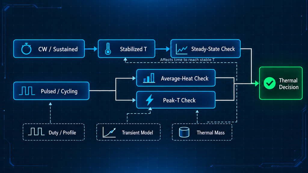
For CW or sustained operation, the PA must remain within its thermal boundary after the relevant heat path approaches a stabilized condition. A short-duration test cannot prove continuous thermal capability merely because the temperature has not yet stabilized.
For integration screening, thermal mass mainly affects how quickly temperatures approach a new state. It does not replace a defined steady-state thermal resistance or an applicable transient thermal model.
Pulsed operation adds another boundary. Average dissipation can help size system-level cooling, but average power alone does not prove that a semiconductor junction remains within its applicable limit during each pulse.
Transient behavior may depend on:
- pulse duration;
- repetition pattern;
- transient thermal impedance;
- heat spreading;
- thermal time constants;
- temperature at the start of each pulse or burst.
A low duty cycle therefore does not create a universal “pulse-safe” condition.
If the decision depends on junction temperature during a transient event, do not infer junction safety from the steady-state external thermal budget. Obtain applicable transient thermal data, a valid model, or representative measurement evidence.
In practice:
- CW and sustained operation depend strongly on the steady-state thermal path;
- pulsed operation may require both average-heat and transient-peak analysis;
- repeated cycling can create thermal states that one average-power number does not represent.
Use the simplified thermal budget only when its time assumptions match the actual operating profile.
6. How Should Thermal Derating and Protection Boundaries Be Defined?
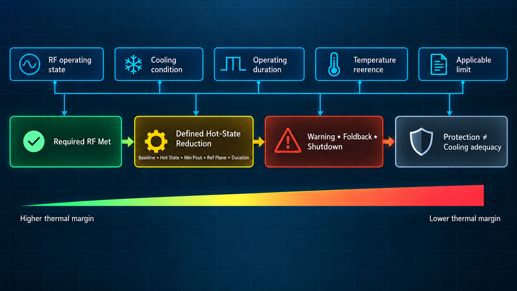
A complete integration decision needs a Thermal Operating Envelope that separates normal performance, allowed derating, and protection.
Over-temperature protection is a safety function. It is not evidence that the cooling system is adequate during normal operation.
Normal Operating Boundary
Inside the normal region, the PA should meet required RF performance without relying on warning, foldback, or shutdown.
Define this region using:
- RF operating state;
- cooling condition;
- required duration;
- physical temperature reference;
- applicable temperature limit.
Derating Boundary
If the project permits reduced RF performance at elevated temperature, define:
- the normal-temperature baseline;
- the applicable hot condition;
- the allowed reduction;
- minimum required
Pout; - the RF reference plane;
- the required duration or operating state.
This converts hot-state power reduction from an unexplained loss into a controlled operating condition.
In a high-temperature C-UAS cabinet, the team must additionally define how much RF reduction is acceptable, at what temperature reference, for which duration, and at which output plane. The C-UAS hot-cabinet RF PA derating framework addresses that narrower application case without replacing the generic Thermal Operating Envelope defined here.
Protection Boundary
Protection behavior may include:
- warning;
- controlled foldback;
- shutdown;
- recovery or restart.
Do not assign universal temperature thresholds. The applicable threshold must come from valid product evidence, verified supplier information, or an agreed project requirement tied to a known physical temperature point.
The sequence can therefore be expressed as:
Normal operation → reduced thermal margin → allowed derating, if defined → protection or stop
If the project has not defined an acceptable derating region, lower RF performance should not be accepted simply because the PA has not shut down.
Likewise, protection activation does not demonstrate adequate cooling. It may show that the intended operating boundary has already been exceeded.
7. What Must Be Validated Before the Thermal Integration Is Released?
A calculated heat load or thermal-resistance budget is a design input. It is not proof of installed thermal performance.
Before release, align validation with the decision-relevant conditions:
- RF operating state;
- RF reference plane and correction method;
- load condition;
- loaded DC state;
- mounting and cooling configuration;
- worst-case cooling-reference condition;
- defined temperature point;
- stabilization rule or test duration;
- hardware/configuration;
- evidence scope;
- measured
Pout,Vdc, andIdc; - observed derating or protection state.
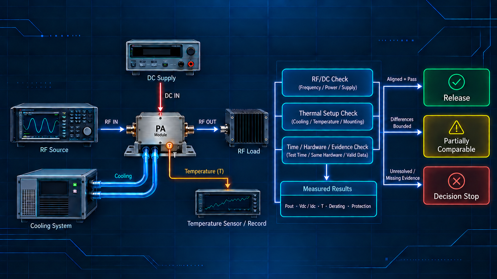
Factory and installed-system results are comparable only when the decision-relevant RF state, RF reference plane and correction method, load condition, DC state, cooling boundary, temperature reference, stabilization rule, hardware/configuration, and evidence scope are aligned.
They may be partially comparable when material differences are identified and bounded. Where material differences remain unresolved, do not treat the results as proof of the same condition.
Thermal Release Evidence Map
| Buyer Requirement | Required Evidence | Required Condition | Evidence Scope | Decision Use |
|---|---|---|---|---|
| Heat-load input is valid | RF/DC operating data and reconciled energy boundary | Same boundary, reference definition, and operating or averaging interval | Same module/configuration or explicitly bounded dataset | Can Pheat be accepted as the cooling-design input? |
| Thermal path is defined | Named physical endpoints, mounting boundary, and cooling condition | Final or representative thermal path | Evaluated mounting/cooling configuration | Is the thermal-resistance budget physically meaningful? |
| Operating envelope is defined | Normal, derating, protection limits and temperature reference | Applicable RF state and cooling condition | Applicable product or project limit scope | Is operation inside the defined thermal envelope? |
| Installed performance can be evaluated | Identified hot-state RF/DC/temperature record | Final or demonstrably comparable condition | Identified unit/configuration or defined representative sample scope | Does the evidence support the installed-state decision? |
When the remaining uncertainty is whether RF output, DC loading, and the defined temperature point remain acceptable after the hardware reaches the required hot state, the calculation has reached a Decision Stop. At that Decision Stop, RF PA power verification after thermal soak must confirm stabilized Pout, loaded DC, and the defined temperature point under matched or explicitly reconciled conditions.
For a high-power C-UAS installation, approval may additionally depend on whether the tested hardware, cooling state, and evidence scope represent the actual application decision.
Move from calculation to physical validation when the remaining uncertainty depends on final mounting, actual cooling behavior, stabilized hot-state performance, product-specific thermal data, or evidence that the model-neutral budget cannot establish.
Conclusion
RF PA thermal management is an integration-budget and operating-envelope problem, not simply a heatsink-selection problem.
A defensible design needs a heat load tied to one electrical/RF boundary, a named temperature reference and limit, a defined cooling reference, a physical thermal path, a realistic installation environment, an applicable duty profile, and explicit derating and protection boundaries.
With those inputs, the engineering team can establish an RF PA Thermal Integration Budget and a Thermal Operating Envelope before the mechanical and cooling design is frozen.
That framework does not define an unknown junction limit, create a missing θJC or transient thermal parameter, prove a specific PA configuration at hot state, or convert a calculated thermal-resistance requirement into installed-system evidence.
Before contacting a supplier or approving the cooling design, consolidate the RF/DC operating point, worst-case environment, controlled temperature point and limit, mounting/cooling condition, duty profile, and derating/protection requirements into one thermal integration record.
If a required limit, model-specific thermal parameter, or decision-relevant evidence condition is missing, request that evidence before making the associated thermal claim.
Engineering Review and Product Discovery Route
| Project Inputs to Define | Engineering Review Focus | Next Route |
|---|---|---|
Frequency, target Pout, RF output reference plane, and Pin where applicable | Establish the RF operating state that drives the thermal load | RF operating-point review |
Vdc, current constraints, waveform, duty cycle, and required duration | Define the electrical burden and heat-generation condition | Thermal-budget review |
| Ambient or inlet temperature, mounting method, heatsink/cold-plate boundary, and cooling condition | Confirm the installed cooling boundary and thermal margin | Cooling and integration review |
| Temperature reference, allowed derating, and warning/foldback/shutdown requirements | Define the Thermal Operating Envelope | Operating-envelope review |
| RF/DC and thermal inputs are sufficiently defined | Review standard or custom PA configurations | Custom RF Power Amplifier Modules |
For a project-specific engineering review, provide the defined RF/DC operating point, cooling boundary, temperature reference and limit, duty profile, and derating/protection requirements.
RF SKYPOWER can then use those inputs for standard or custom PA configuration discovery and further engineering review; configuration discovery by itself does not prove that a specific PA is thermally suitable for the installed system.