


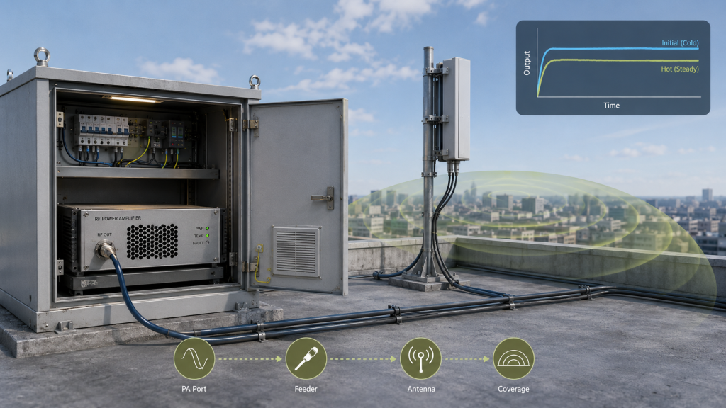
Continuous RF Output can drop in rooftop C-UAS systems when short RF power bursts are mistaken for long-duration output proof under real thermal, supply, antenna-load, and protection conditions.A short burst can prove that a module reaches a target wattage briefly, but it cannot prove that the same usable output will stay stable inside an outdoor rooftop cabinet after heat, current demand, feeder loss, antenna VSWR, and control feedback are included.
The central conflict is simple: short burst output proves instant output capability, but continuous output proves long-duration system stability. For rooftop C-UAS sites, the practical question is not only whether a module can reach 100W or 200W for a short test. The harder question is whether the system can hold the required antenna-port output during the real duty cycle, cabinet temperature, supply condition, antenna path, and monitoring mode.
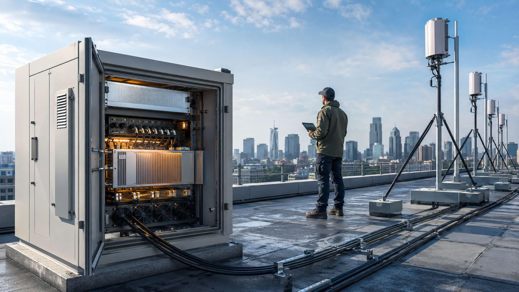
This matters because urban rooftops often combine sun exposure, sealed cabinets, long antenna routes, multi-band operation, remote control, limited maintenance access, and high-duty security periods. If output falls after warm-up, the cause may be thermal accumulation, voltage drop, load mismatch, feeder loss, protection behavior, or module design limits. A serious review of continuous output helps engineers separate these causes before a short test result becomes false confidence.
1. What Short Bursts Miss About Continuous RF Output
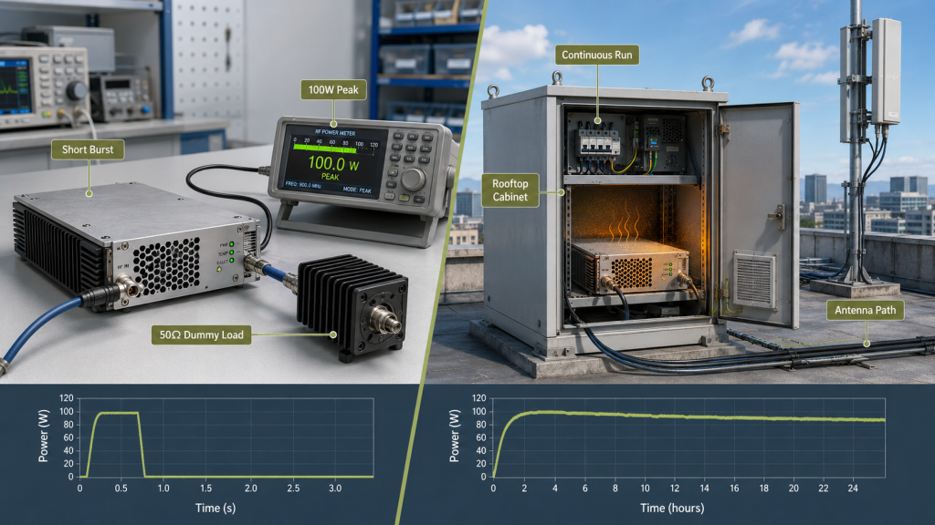
Short RF power bursts do not prove RF Power Amplifier Continuous Output because they show only brief output capability before thermal, supply, load, and protection stress have fully accumulated. A module may reach the target wattage during a short factory test, but that does not mean the same wattage will remain stable after long operation in a rooftop cabinet.
Here’s the engineering point: short tests show whether the amplifier can reach the number; continuous tests show whether it can hold the number. For rooftop C-UAS systems, that difference can decide whether the installed RF chain remains predictable during real operation.
What Does a Short Burst Actually Prove?
A short burst proves that the RF path can produce a target output under a limited condition. It may confirm drive level, basic PA health, initial gain, and startup behavior, but it may not reveal long-duration drift.
A short burst may not expose:
- Heat accumulation inside the module
- Hot-state supply voltage drop
- Cabinet air temperature rise
- Long feeder and antenna load behavior
- VSWR protection during sustained operation
- Output drift after several minutes or hours
- Multi-band simultaneous load
When selecting RF Power Amplifier modules for C-UAS integration, engineers should confirm whether the required output is burst output, duty-limited output, or continuous output under rooftop site conditions.
Why Does Continuous Output Reveal More?
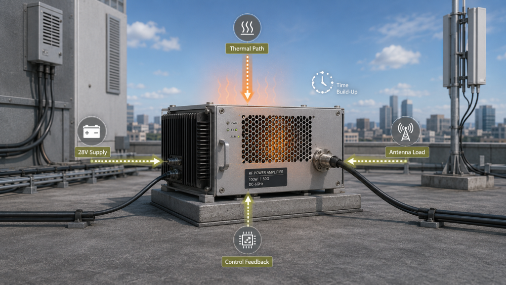
Continuous output reveals what happens after the RF Power Amplifier reaches its real operating boundary. Heat must move from the RF device into the PCB, housing, heatsink, cabinet air, and outdoor environment. Current must remain stable through the 28V supply path. The antenna load must remain safe enough to avoid repeated reflected-power events.
Key Takeaway: Short RF power bursts are valid startup evidence, but they do not prove continuous usable output under sustained rooftop C-UAS conditions.
| Wrong Assumption | Better Check | Engineering Risk |
|---|---|---|
| Short 100W means continuous 100W | Run long-duration output testing | Hidden thermal drift |
| No alarm in short test means safe | Record protection status over time | Late alarm events |
| Dummy load pass proves field use | Test with real antenna-path assumptions | Load mismatch risk |
| Initial voltage is enough | Measure module-terminal voltage under load | Output drop after current rises |
This table helps engineers separate instant output capability from sustained operating stability.
2. When Is Pulse-Like RF Output Still Acceptable?
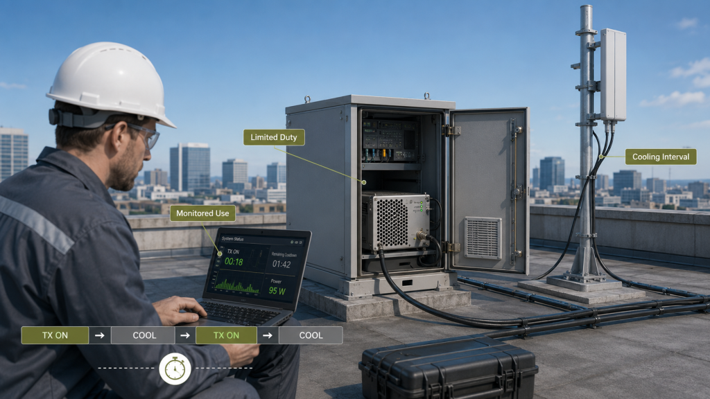
Pulse-like RF output is acceptable when RF Power Amplifier Continuous Output is not the project requirement and the mission uses short operation, limited duty cycle, defined cooling intervals, and clear acceptance boundaries. Not every C-UAS project needs continuous full-power operation. The problem appears when a short-duty module is presented as if it can support sustained rooftop output.
The practical risk is clear: burst output is not wrong, but it must be described honestly. If the customer expects continuous operation and the supplier only proves burst output, both sides may approve different products on the same wattage label.
Which Conditions Support Burst or Duty-Limited Use?
Pulse-like output can be reasonable when the mission is short, monitored, and controlled. In these projects, the operating model itself includes recovery time or limited run duration.
Pulse-like output may be acceptable when:
- The system runs only during short events
- Duty cycle is limited and documented
- Cooling intervals are defined
- Operators monitor temperature and alarms
- The site is not an unattended fixed station
- Acceptance requires only short-duration output
- The customer does not expect continuous full power
If the system is not expected to run continuously, the buyer should still define RF Power Amplifier duty cycle so burst output, high-duty output, and True CW operation are not confused during acceptance.
What Should Be Defined in the File?
The file should define the output mode before wattage is judged. “100W” is incomplete unless the reader knows whether it means peak, burst, duty-limited, or continuous output. A clear duty-cycle file should state single run duration, work/rest cycle, cooling interval, ambient condition, and protection behavior.
Key Takeaway: Pulse-like RF output can be a valid design choice, but it must not be confused with continuous full-power capability.
| Output Mode | Valid Use Case | What Must Be Defined |
|---|---|---|
| Burst output | Short triggered operation | Burst duration |
| Duty-limited output | Planned work/rest cycle | Duty cycle and cooling interval |
| Continuous output | Long-duty rooftop operation | Run time and thermal condition |
| Unknown mode | Poor RFQ or report | Acceptance dispute |
This table helps buyers avoid comparing output modes that are not technically equivalent.
3. How to Check Continuous RF Output on Rooftops
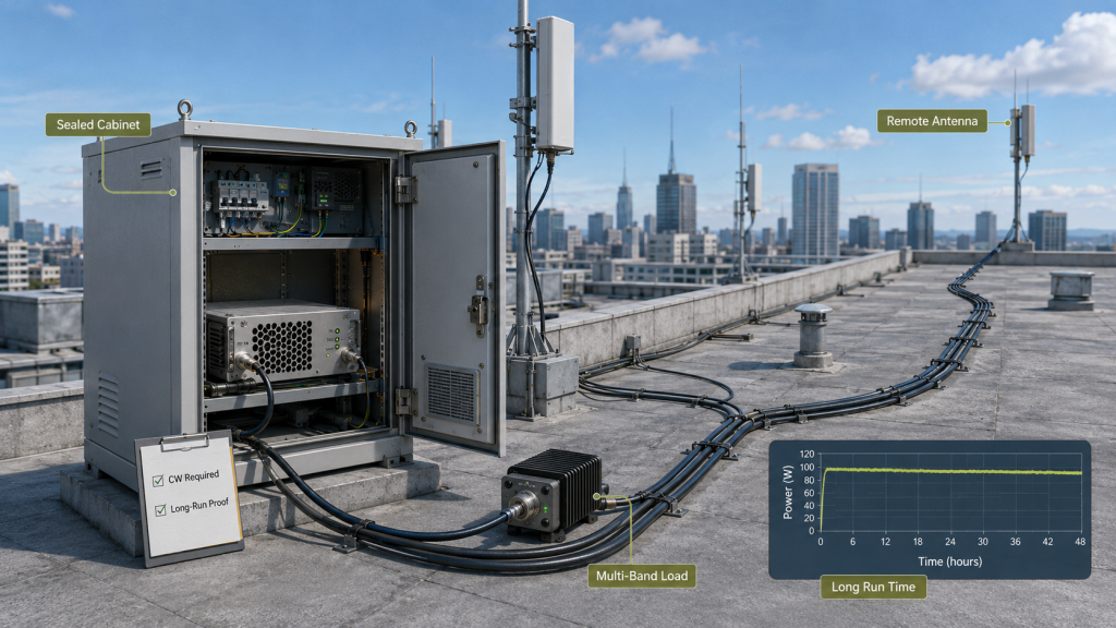
Continuous output becomes a selection requirement when RF Power Amplifier Continuous Output is needed for long-duration rooftop C-UAS operation without relying on cooling pauses, manual resets, or short-duty assumptions. If the site must stay ready during long security windows, the amplifier should be reviewed as a sustained operating component, not a short-test component.
This is where system integrators should pay attention: rooftop C-UAS sites often look simple from a layout drawing, but they can be harsh from an RF operating perspective. Sun exposure, sealed cabinets, multi-band load, remote antennas, and limited maintenance access make continuous output a selection requirement rather than an optional reliability detail.
Which Rooftop Conditions Trigger the Requirement?
Continuous output should be confirmed when the system must run through long events, high-alert periods, or unattended security windows. It is also required when maintenance teams cannot easily reach the rooftop to reset, cool, or reconfigure equipment.
Treat continuous output as a selection requirement when you see:
- Long-duration rooftop watch duty
- Outdoor cabinet installation
- Summer sun exposure
- Multi-band modules running together
- Remote or elevated antenna positions
- Long DC supply routes
- Long feeder routes
- Unattended monitoring
- Acceptance based on long-run output
- Frequent alarm resets are unacceptable
For rooftop systems, RF Power Amplifier ambient temperature should be reviewed because continuous output can expose heat accumulation that short burst testing does not show.
Why Is Rooftop Duty Different From Bench Duty?
Bench duty is usually controlled, supervised, and short. Rooftop duty may combine high cabinet temperature, high current draw, real antenna VSWR, feeder loss, weatherproof interfaces, and remote control. The same module can behave differently when all those conditions appear together.
Key Takeaway: Continuous output becomes a selection requirement when the rooftop mission depends on stable output over time, not only a clean startup reading.
| Field Condition | Why It Matters | Selection Impact |
|---|---|---|
| Long security window | Output must remain stable | Require long-duration proof |
| Sealed rooftop cabinet | Heat accumulates inside | Review thermal path |
| Multi-band operation | Heat and current stack | Test simultaneous load |
| Remote maintenance | Reset is costly | Require protection evidence |
| Real antenna path | Load may differ from dummy load | Check VSWR behavior |
This table helps RFQ teams know when continuous output must be written into the selection requirement.
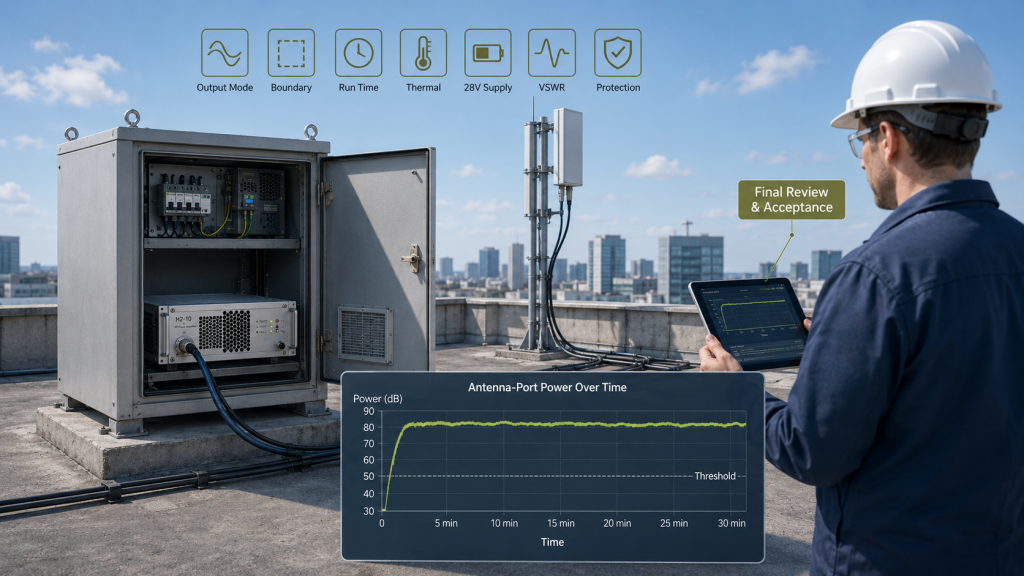
4. How Does Continuous Output Change Real C-UAS Performance?
Continuous output changes real C-UAS performance because RF Power Amplifier Continuous Output determines whether antenna-port power remains stable after warm-up, not only whether a short peak output was measured. A rooftop system depends on usable power over the required run time, not a single reading taken before heat, voltage drop, or protection behavior appears.
Here’s the field reality: if the output falls after several minutes, the original peak wattage may no longer describe the installed system. The site may still look normal from a module label, but the antenna-port power has changed.
Where Does Performance Drift Appear?
Performance drift can appear as output reduction, alarm events, unequal band behavior, or field retest disagreement. The symptom may look like an RF failure even when the root cause is thermal, electrical, or load-related.
Common signs include:
- Output falls after warm-up
- High-band channels drop first
- Temperature alarm appears during long duty
- VSWR alarm appears after antenna connection
- Module-terminal voltage falls under load
- Field output differs from short factory result
- System becomes stable again after cooling
A short burst may confirm rated output, but RF Power Amplifier usable output must be checked under the run time, duty cycle, and installed RF path required by the system.
Why Is the Antenna-Port Result More Important?
The antenna-port result matters because the system uses delivered output, not module-label power. If continuous operation reduces PA-port output or feeder-path delivery, the antenna-side result changes as well.
In Low-Altitude Security & C-UAS EW Solutions, rooftop RF systems should be judged by long-duration antenna-port power, not only short RF power bursts measured at the PA port.
Key Takeaway: Continuous output affects system performance by determining whether usable antenna-port power remains stable after the system reaches hot-state operation.
| Performance Symptom | Possible Cause | Better Check |
|---|---|---|
| Output drops after minutes | Thermal accumulation | Hot-state output trend |
| Output drops under all bands | Supply voltage sag | Module-terminal voltage |
| One band drops first | Frequency or feeder sensitivity | Band-by-band test |
| Alarm appears with antenna | Load mismatch | VSWR and reflected power |
| Field result differs from report | Boundary mismatch | Compare measurement point |
This table helps engineers connect performance drift to measurable system conditions.
5. What Do Rooftop C-UAS Sites Reveal About Stability?
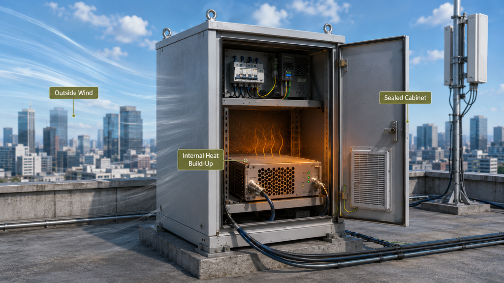
Rooftop C-UAS sites reveal RF Power Amplifier Continuous Output problems because sun exposure, cabinet heat, long antenna paths, simultaneous channels, and remote maintenance make short burst testing insufficient. A rooftop may feel windy and open, but the PA module usually operates inside a cabinet, not in free air.
The better check is simple: judge continuous output from the cabinet and antenna-path condition, not from the weather outside the building. Rooftop wind does not automatically remove heat from a sealed enclosure or from the device junction inside the PA.
Which Rooftop Factors Create Stress?
Urban rooftops can combine RF, thermal, electrical, and mechanical stress in the same site. A short factory setup may not include those variables.
Rooftop stress factors include:
- Direct sun exposure on the cabinet
- Higher internal cabinet temperature
- Limited airflow through sealed enclosures
- Antennas placed away from the cabinet
- Long or bent feeder routes
- Lightning protection and waterproof joints
- Metal structures near antennas
- Multiple RF channels running together
- Remote monitoring instead of local maintenance
In a city rooftop or urban venue C-UAS deployment, sun exposure, cabinet heat, long cable paths, and temporary installation pressure can make continuous RF output harder to sustain than short bursts.
Why Is Wind Not Enough Evidence?
External wind may cool the cabinet surface, but it does not prove that the PA device, copper spreader, internal airflow, and cabinet air temperature have reached a safe steady state. For rooftop systems, the real question is not whether the site feels ventilated, but whether the installed RF chain can hold output after the cabinet, supply path, antenna path, and protection feedback have all reached long-duration operating conditions.
The Urban Shield case shows why dense metropolitan venues require attention to thermal stability, power continuity, status feedback, and controlled RF behavior. Rooftop and venue environments may differ, but both expose the gap between clean specifications and real installed operation.
Key Takeaway: Rooftop sites reveal stability problems because they combine sustained load with cabinet heat, real antenna paths, and limited maintenance access.
| Rooftop Condition | Stability Risk | Better Review |
|---|---|---|
| Sun-exposed cabinet | Higher internal temperature | Hot-cabinet test |
| Windy rooftop | False cooling confidence | Check internal thermal path |
| Remote antenna | Feeder loss and VSWR risk | Antenna-port output |
| Multi-band operation | Heat and current stacking | Simultaneous run test |
| Limited maintenance | Slow troubleshooting | Alarm and feedback record |
This table helps teams avoid treating rooftop installation as a simple bench extension.
6. What Breaks Continuous RF Output on Rooftops
Thermal, supply, load, and control stress build up during RF Power Amplifier Continuous Output because sustained RF conversion pushes the module toward its real operating boundary. Short bursts may finish before the thermal path, DC path, antenna load, and protection logic reach their steady-state limits.
This is the selection risk: if each stress is checked separately and briefly, the system may look safe. When all stresses appear together during rooftop operation, the output can drift, derate, or trigger protection.
How Does Thermal Stress Accumulate?
Thermal stress accumulates from the RF device through the PCB, housing, thermal interface, heatsink, cabinet air, and outdoor environment. A short burst may heat the transistor, but continuous output tests whether heat can leave the system fast enough.
Continuous output depends on thermal strategies for high-power C-UAS modules, especially when RF modules operate inside rooftop cabinets where internal airflow may be weaker than the outdoor wind suggests.
Review these items:
- GaN device hot-state behavior
- PCB and housing heat transfer
- Copper heat spreading or heatsink path
- Cabinet airflow and spacing
- Ambient and cabinet temperature
- Output trend after heat soak
How Do Supply, Load, and Control Stress Add Up?
Long-duration operation should also check 28V RF Power Amplifier supply margin, because voltage drops may appear only after sustained current load, not during a short startup test. The antenna path also matters: reflected power, feeder loss, connectors, and rooftop transitions can affect protection behavior.
For RF Power Amplifier modules, CNC housing, copper heat spreading, PCB design, temperature / VSWR / voltage protection, and repeatable test reports should be evaluated together when customers require continuous output. This is where source-factory engineering support has value: the discussion is no longer only “how many watts,” but how the PA behaves under sustained thermal, electrical, RF, and control conditions.
Key Takeaway: Continuous output is harder because several small stresses can accumulate into one visible output drop.
| Stress Type | What Builds Up | What to Measure |
|---|---|---|
| Thermal | Heat soak and derating | Output and temperature trend |
| Supply | Voltage drop under current | Module-terminal voltage |
| Load | Reflected power or mismatch | VSWR and alarm status |
| Control | Enable and feedback stability | Status over full run |
| Multi-band | Shared heat and current | Simultaneous output data |
This table helps engineers test combined stress instead of approving each item in isolation.
7. How Do CW-Rated, Duty-Limited, and Burst Designs Differ?
CW-rated, duty-limited, and burst-oriented designs differ because RF Power Amplifier Continuous Output assumes different thermal margin, supply capacity, device stress, protection behavior, and operating time than burst output. These designs are not interchangeable just because their peak wattage labels look similar.
Here’s the practical point: a stronger burst number is not always the better rooftop choice. The better module is the one whose output mode matches the required duty cycle and installation condition.
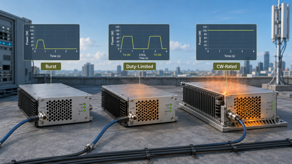
What Is a CW-Rated Design?
A CW-rated or continuous-output design is built for sustained output under defined load, thermal, and supply conditions. It usually prioritizes stable hot-state behavior rather than the highest short peak.
For continuous operation, GaN device quality for RF Power Amplifiers matters because full-load stability depends on junction temperature, bias drift, current density, mismatch tolerance, and hot-state repeatability, not only peak output capability.
A CW-oriented review should check:
- Long-duration output trend
- Hot-state gain and output stability
- Thermal resistance and device margin
- Full-load current behavior
- Protection threshold behavior
- S/N-linked test evidence
What Are Duty-Limited and Burst-Oriented Designs?
A duty-limited design can be valid when run time and cooling intervals are clear. A burst-oriented design can also be valid for short triggered use. The risk appears when a duty-limited or burst-oriented module is used as if it were a continuous rooftop PA.
If the project requires long remote operation, buyers should also review RF Power Amplifier reliability testing so output evidence, protection status, thermal behavior, and acceptance conditions are not separated from the real operating duty.
Key Takeaway: The output mode is part of the product specification; peak wattage alone does not define the correct PA design.
| Design Type | Best Fit | Main Risk |
|---|---|---|
| CW-rated | Long rooftop duty | Needs strong thermal and supply support |
| Duty-limited | Defined work/rest cycle | Misused as continuous output |
| Burst-oriented | Short triggered operation | Overrated for long duty |
| System derating | Stability-first design | Must be documented clearly |
This table helps buyers compare output modes instead of comparing wattage labels alone.
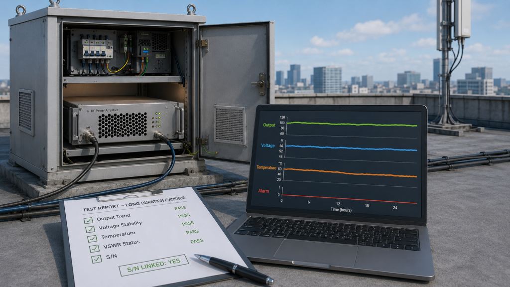
8. How to Prove Continuous RF Output Stability
Protection logic and test evidence should prove RF Power Amplifier Continuous Output by recording long-duration output, temperature behavior, voltage stability, current trend, load condition, and alarm feedback. A short peak reading is not enough evidence for rooftop C-UAS operation.
The practical risk is clear: without protection status, you only know that output dropped; you do not know whether it dropped because of heat, voltage, reflected power, current limit, control logic, or module weakness.
What Should a Continuous Output Report Include?
A useful continuous-output report should define the output mode and the conditions used to prove it. It should not hide behind a single wattage screenshot.
Request evidence around:
- Burst, duty-limited, or continuous mode
- Test duration
- Frequency and output reference point
- PA-port or antenna-port boundary
- Ambient and cabinet temperature
- Module-terminal voltage and current
- Output trend over time
- Temperature trend over time
- VSWR or reflected-power status
- Voltage, temperature, and current alarms
- Recovery behavior after protection events
- S/N-linked test condition and unit record
For rooftop C-UAS acceptance, continuous-output evidence should also be tied to the module S/N, test duration, measurement boundary, load condition, voltage trend, temperature trend, and protection status. Without S/N-linked long-duration data, a buyer may know that one test passed, but not whether the same unit, under the same boundary, can be compared fairly during customer retesting.
How Does Protection Feedback Help Diagnosis?
Protection feedback helps explain whether output reduction is controlled protection or uncontrolled weakness. If continuous output becomes unstable after connecting the rooftop antenna, engineers should review RF Power Amplifier VSWR protection before judging the module alone.
A stable RF Power Amplifier control interface should report thermal state, RF output state, reflected-power behavior, supply health, and fault identity so the controller can distinguish normal operation from protection-limited output. VSWR / temperature / voltage protection is valuable not only because it protects the module, but also because it helps engineers determine whether continuous output decline comes from load, heat, supply, or the RF Power Amplifier itself.
Key Takeaway: Continuous output proof should show the output trend and the reason behind any output change.
| Weak Evidence | Better Evidence | Why It Matters |
|---|---|---|
| One peak wattage | Output trend over time | Shows stability |
| No duration listed | Defined continuous run | Prevents burst confusion |
| No voltage record | Module-terminal voltage | Finds DC sag |
| No alarm status | Protection feedback | Explains derating |
| No boundary stated | PA-port or antenna-port point | Supports retest |
| No S/N link | Unit-specific test evidence | Reduces acceptance disputes |
This table helps procurement teams request evidence that can diagnose output behavior, not only approve a number.
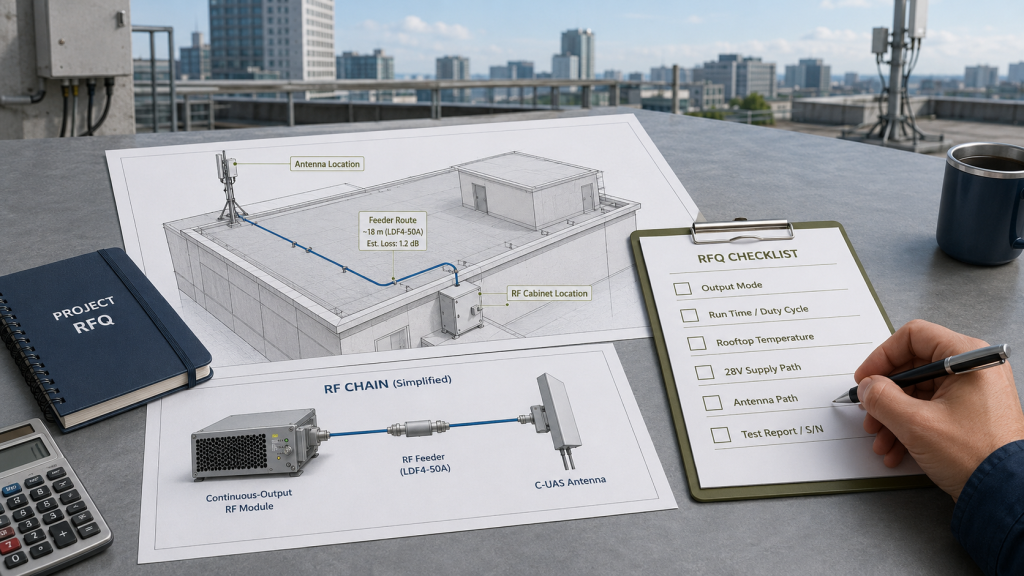
9. What RFQ Data Defines Continuous RF Output
Buyers should define RF Power Amplifier Continuous Output requirements before quotation by sharing output mode, run time, duty cycle, rooftop temperature, cooling condition, supply path, antenna path, and test requirements. If the RFQ only says “100W,” the supplier cannot know whether the buyer means short burst, duty-limited output, or rooftop continuous operation.
This is where procurement and engineering must use the same language. Continuous output is not only a wattage number; it is a wattage number under time, heat, supply, load, and boundary conditions.
What RFQ Data Matters Most?
The RFQ does not need perfect final drawings, but it should provide enough operating context to avoid the wrong module choice.
Share these items:
- Target frequency bands
- Target output power
- PA-port, cabinet, feeder-end, or antenna-port target
- Burst, duty-limited, or continuous mode
- Single run duration
- Daily operating time
- Duty cycle
- Rooftop ambient temperature
- Expected cabinet temperature
- Cooling method and cabinet airflow
- 28V supply design and cable length
- Antenna distance and feeder length
- Connector, adapter, and lightning-protection count
- Real antenna VSWR requirement
- Required protection feedback
- Required continuous-output test report
For rooftop projects, antenna distance affects RF Power Amplifier selection because long feeder paths can change antenna-port power during real deployment.
Why Is “100W Continuous” Still Incomplete?
“100W continuous” is better than “100W,” but it is still incomplete without duration, temperature, voltage, load, and measurement boundary. A 100W continuous PA-port target under a controlled dummy load is not the same as 100W antenna-port output after rooftop feeder loss.
If the antenna sits away from the rooftop cabinet, RF Power Amplifier feeder and connector loss should also be reviewed before the buyer assumes that PA-port continuous output equals antenna-port continuous output.
Key Takeaway: A strong RFQ defines continuous output as an operating condition, not a marketing phrase.
| RFQ Item | Why It Matters | Risk If Missing |
|---|---|---|
| Output mode | Defines burst or continuous need | Wrong design path |
| Run time | Defines stress duration | Short-test approval |
| Measurement point | Defines valid wattage | PA-port vs antenna-port dispute |
| Rooftop temperature | Defines thermal stress | Hidden hot-site failure |
| Supply path | Defines voltage stability | Output drop under load |
| Antenna path | Defines real RF load | VSWR and loss surprise |
This table helps buyers turn continuous output into a measurable requirement before price is locked.
10. How to Judge Continuous RF Output Stability
RF Power Amplifier Continuous Output is stable enough only when the installed RF chain can hold the required antenna-port power over the required run time without relying on repeated thermal recovery, voltage recovery, or protection-triggered pauses. The goal is not only to reach output once. The goal is to hold usable output under the real rooftop operating condition.
Here’s the final decision point: if the module can pass only before heat, load, and supply stress appear, the selection is not finished.
What Decision Sequence Should Engineers Use?
Use a sequence that starts with the output mode and ends with installed evidence. Do not start only with the highest wattage label.
A practical sequence is:
- Define burst, duty-limited, or continuous output.
- Define PA-port, cabinet, feeder-end, or antenna-port target.
- Define required run time and duty cycle.
- Confirm rooftop ambient and cabinet temperature.
- Measure module-terminal voltage under full load.
- Review thermal path and cabinet airflow.
- Check antenna, feeder, connector, and VSWR behavior.
- Record temperature, voltage, current, and alarm status.
- Compare short-run and long-run output.
- Confirm repeatable test evidence before final approval.
Before judging continuous output, engineers should define RF power measurement points so PA-port power, cabinet output, feeder-end power, and antenna-port power are not mixed.
When Should the System Be Adjusted?
The system should be adjusted when output falls, alarms appear, voltage drops, temperature rises too quickly, or antenna-port power cannot remain predictable. The fix may be stronger cooling, lower-loss feeder, better supply margin, output derating, different PA architecture, improved antenna match, or changed cabinet placement.
As an RF Power Amplifier module and C-UAS core component source factory, RF SKYPOWER can support rooftop C-UAS projects by reviewing output mode, duty cycle, antenna distance, cabinet temperature, supply margin, thermal path, protection status, and continuous-output test evidence before final approval. This moves the discussion beyond “how many watts for a few seconds” and toward real installed stability.
This is where source-factory engineering support becomes useful: the supplier should help separate a real PA limitation from a rooftop cabinet problem, a DC supply drop, a feeder-path loss issue, a VSWR-triggered protection event, or a test-boundary mismatch.
Key Takeaway: Stable continuous output means the system can hold usable antenna-port power under the defined rooftop duty condition.
| If the Problem Is… | Start With… | Avoid First |
|---|---|---|
| Output drops after warm-up | Thermal and voltage trend | Blaming PA immediately |
| Alarm appears with antenna | VSWR and feeder path | Ignoring load condition |
| Voltage falls under load | 28V supply path | Raising RF drive blindly |
| Cabinet gets too hot | Thermal path and airflow | Assuming rooftop wind solves it |
| Field test differs from factory | Boundary and duration | Comparing unlike tests |
This table gives engineering and procurement teams a practical final review path before approving continuous output.
FAQ
Can I use a short RF power test to approve continuous output?
No. A short RF power test can prove startup output, but it cannot prove RF Power Amplifier Continuous Output. You should also review run time, duty cycle, hot-state output, module-terminal voltage, load condition, and protection status.
What should I check before asking for continuous RF output?
Start with output mode, measurement boundary, run duration, duty cycle, rooftop temperature, cabinet cooling, 28V supply margin, antenna path, VSWR behavior, and required test evidence. These details define whether the requested wattage is realistic.
How do I know if output drop is thermal or power-supply related?
Compare output, temperature, current, and module-terminal voltage over time. If output drops as temperature rises, thermal margin is likely involved. If voltage falls under load, the DC supply path may be limiting the module.
What’s the best proof of continuous RF Power Amplifier output?
The best proof is a repeatable long-duration test record showing output power, voltage, current, temperature, load condition, VSWR status, alarm feedback, S/N-linked test data, and measurement boundary under conditions close to the intended rooftop duty cycle.
When should I choose a CW-rated RF Power Amplifier?
Choose a CW-rated RF Power Amplifier when the system must operate for long periods, support high duty cycle, run unattended, or maintain antenna-port output without repeated cooling intervals. Duty-limited or burst-oriented modules should be used only when their limits match the mission.
Conclusion
Continuous RF output is harder than short RF power bursts because sustained operation forces the whole RF chain to reach its real thermal, supply, load, and protection boundary. A short burst can show that an RF Power Amplifier reaches target output briefly, but it cannot prove that the same output will remain stable inside a rooftop cabinet, under long duty cycle, with real antenna paths, high ambient temperature, and remote C-UAS operation.
For system integrators, RF engineers, and procurement reviewers, the practical lesson is clear: define the output mode before approving the module. Confirm whether the requirement is burst output, duty-limited output, or continuous output. Then review measurement boundary, run time, duty cycle, module-end voltage, thermal path, antenna load, VSWR status, temperature protection, voltage protection, and repeatable long-duration test evidence.
RF SKYPOWER supports rooftop C-UAS RF Power Amplifier selection by reviewing burst output, duty-limited output, continuous output, antenna-port power, duty cycle, thermal margin, supply stability, protection status, and repeatable test evidence before final project approval. If your rooftop C-UAS project has not confirmed duty cycle, continuous run time, antenna-port power, thermal margin, supply stability, and protection feedback, you can review your RF Power Amplifier continuous output with a source-factory engineering team before final approval.
If you want to align rooftop output mode, antenna-port target, thermal path, 28V supply margin, VSWR feedback, and long-duration test evidence before quotation, you can also discuss your project with RF SKYPOWER before the site layout becomes expensive to change.
Field-ready rooftop C-UAS performance starts with proven continuous output, not a short burst that looks strong only before the system gets hot.