











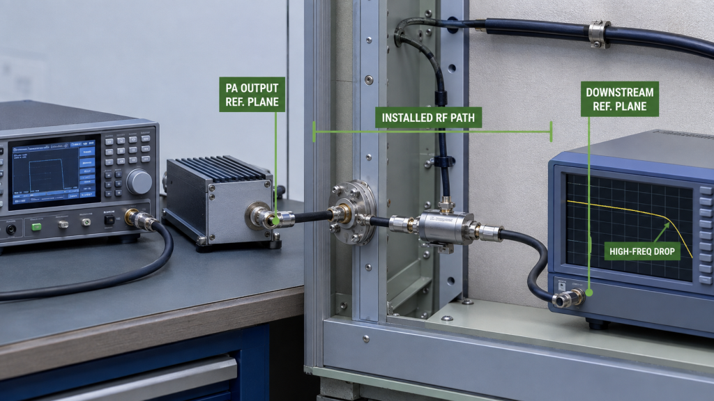
A high-frequency output drop that appears after the installed RF path is added does not automatically mean the RF PA becomes weak at the upper frequency point. The PA may still meet its requirement at the defined output reference plane while the downstream RF result changes after the feeder, connectors, filters, lightning protection, or antenna interface are added.
For a custom RF Power Amplifier Module, the useful comparison is not simply low-band power versus high-band power. Actual Pin, corrected PA-port Pout, downstream measurement definition, load condition, path correction, and reference plane must remain clear before two frequency points or two locations are compared.
When the high-frequency result falls after installation, where does the abnormal difference actually begin: at the PA output reference plane, or somewhere downstream in the installed RF path?
1. Why a High-Frequency Drop After Installation Is Not Yet a PA Diagnosis
A lower high-frequency result is a symptom, not a root-cause diagnosis.
The result may change because of the PA, but it may also change because the installed RF boundary is different from the controlled PA test boundary.
After installation, the RF chain may include:
- cabinet RF routing;
- bulkhead interfaces;
- feeder cable;
- connectors and adapters;
- filters or combiners;
- lightning protection;
- outdoor feedthroughs;
- the antenna feed and antenna.
These elements can introduce frequency-dependent insertion loss, mismatch, or both after the PA output.
The operating conditions may also differ between the controlled and installed tests.
Before comparing results, verify the relevant:
- target frequency;
- Actual Pin or verified PA input drive;
- corrected PA-port Pout;
- load condition;
- Vdc / Idc where relevant;
- cooling and thermal state;
- protection state;
- measurement method;
- measurement reference plane.
The important question is not:
“Is the high-frequency number lower?”
It is:
“At which defined measurement boundary does the result first stop meeting the expected value or project limit?”
A PA that meets its requirement at the defined PA output reference plane should not be rejected only because a downstream result is lower.
Likewise, an unacceptable result already present at the PA output plane should not automatically be blamed on the feeder.
The failing boundary has to be identified first.
2. How to Separate PA-Port Output From Downstream RF Delivery
Start with the PA output reference plane.
PA-port power should be a measured result referenced or corrected to the defined PA output reference plane.
The measurement instrument does not have to be physically connected directly to the PA connector. A directional coupler, attenuator, measurement cable, or sensor may sit between the PA and instrument, provided the applicable path correction is defined and the final result is referenced back to the intended PA output plane.
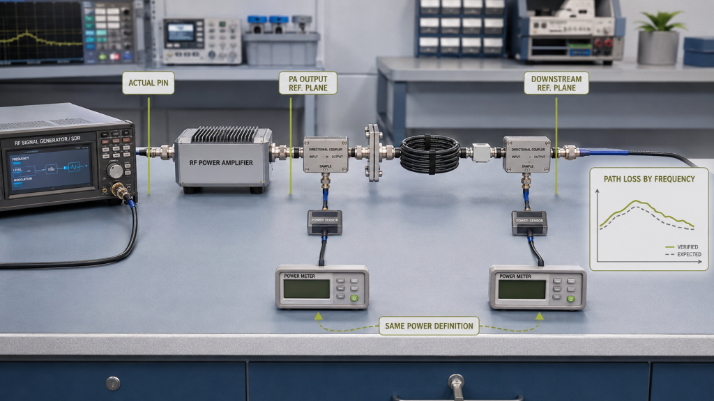
The downstream result must also be tied to a defined reference plane and a defined power quantity.
For example:
- forward power referenced to the antenna-input plane;
- net RF power accepted by a mismatched antenna;
are not automatically the same quantity.
They should not be treated as interchangeable.
When diagnosing installed-path loss, compare measurements referenced to two clearly defined planes using the same power definition. The difference can then be compared with the verified or expected frequency-specific insertion loss between those planes.
A practical isolation sequence is:
- Verify Actual Pin at the affected frequency.
- Test the PA into a known-good load suitable for the relevant frequency and RF power.
- Correct the output result to the defined PA output reference plane.
- Confirm whether PA-port Pout meets the applicable requirement.
- Add the installed RF path.
- Measure the same defined power quantity at the next downstream reference plane.
- Compare the difference with the frequency-specific path-loss budget between those two planes.
- If mismatch is also present, evaluate it separately rather than folding it into insertion loss.
A lower downstream value is not automatically a fault.
Every real RF path introduces some insertion loss.
The diagnostic question is whether the measured difference between the two defined planes is consistent with the expected path budget and the applicable project limit.
If corrected PA-port Pout remains acceptable at the high-frequency point but a comparable downstream measurement falls outside the defined expectation, the investigation should move downstream of the PA reference plane.
That still does not identify whether the cause is excessive insertion loss, mismatch, an interface problem, or an incorrect measurement definition.
If corrected PA-port Pout also fails under the controlled test boundary, the diagnosis should return to the PA-side test boundary.
3. When Does the Installed RF Path Explain the High-Frequency Drop?
Frequency-dependent insertion loss is expected in an RF path.
A feeder may introduce more loss at a higher frequency than at a lower frequency. Connectors, adapters, filters, combiners, and other RF components may also have frequency-dependent insertion loss.
This is why one generic path-loss value should not be applied across a wide operating band without verification.
A feeder cable loss check should define the applicable frequency, installed path, measurement boundary, and correction method rather than treating feeder loss as one constant value.
Separate Insertion Loss From Mismatch
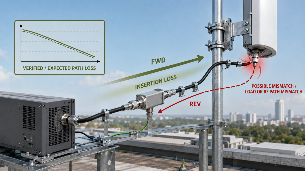
Insertion loss and reflected power can both affect the system result, but they are not the same mechanism.
A lossy feeder can reduce forward power at a downstream reference plane without producing a large VSWR.
A mismatched antenna or RF discontinuity can increase reflected power without proving that feeder attenuation itself increased.
If FWD and REV are obtained from the same valid sensing method and defined measurement plane under comparable operating conditions, a higher REV-to-FWD relationship or worse VSWR is consistent with increased mismatch at that plane.
It does not by itself identify which downstream component caused the change.
It also should not be presented as proof that feeder insertion loss increased.
Where the dominant symptom becomes a reflected-power or VSWR event, use a separate reflected power alarm diagnosis to isolate that condition before hardware is replaced.
Follow the Measurement Boundary
Evidence shifts the investigation downstream when:
- corrected PA-port Pout remains acceptable;
- Actual Pin remains comparable;
- the same affected frequency is used;
- the downstream measurement uses the same defined power quantity;
- the measurement planes and corrections are known;
- the abnormal difference appears only after part or all of the installed RF path is added.
Useful downstream checks may include:
- feeder type and length;
- connector condition;
- adapter count;
- filter or combiner loss;
- lightning protection;
- bulkhead interfaces;
- cable routing or bending;
- antenna matching;
- frequency-specific correction data.
The purpose is not to replace every RF component until the result changes.
The purpose is to determine which defined boundary introduces the abnormal difference, and then separate attenuation, mismatch, and measurement error before assigning a component-level cause.
| Observed Pattern | Boundary to Verify | What the Evidence Can Support |
|---|---|---|
| PA-port passes, downstream result is below the defined expectation | Installed RF path | The abnormal difference occurs downstream of the PA reference plane; insertion loss, mismatch, and measurement definition still need to be separated |
| Corrected PA-port Pout also drops | PA test boundary | The result is not explained by downstream path loss alone |
| Valid FWD / REV data show a higher REV-to-FWD relationship or worse VSWR | Load / RF path | Increased mismatch is consistent with the observation, but the failed component is not yet identified |
| Actual Pin falls at the high-frequency point | PA input boundary | Lower input drive may explain part or all of the Pout reduction |
| Drop appears only after thermal stabilization | Operating condition | Cold-state and stabilized-hot results are not directly interchangeable |
4. When Should the Diagnosis Return to the PA Test Boundary?
If corrected PA-port Pout also drops at the affected high-frequency point, the installed feeder cannot explain the entire result.
At that point, stop expanding the downstream path investigation and return to the controlled PA test boundary.
First confirm that the comparison uses:
- the same target frequency;
- comparable Actual Pin;
- the correct PA output reference plane;
- valid frequency-specific measurement correction;
- a known load condition;
- adequate PA-terminal supply;
- comparable thermal state;
- the applicable protection state.
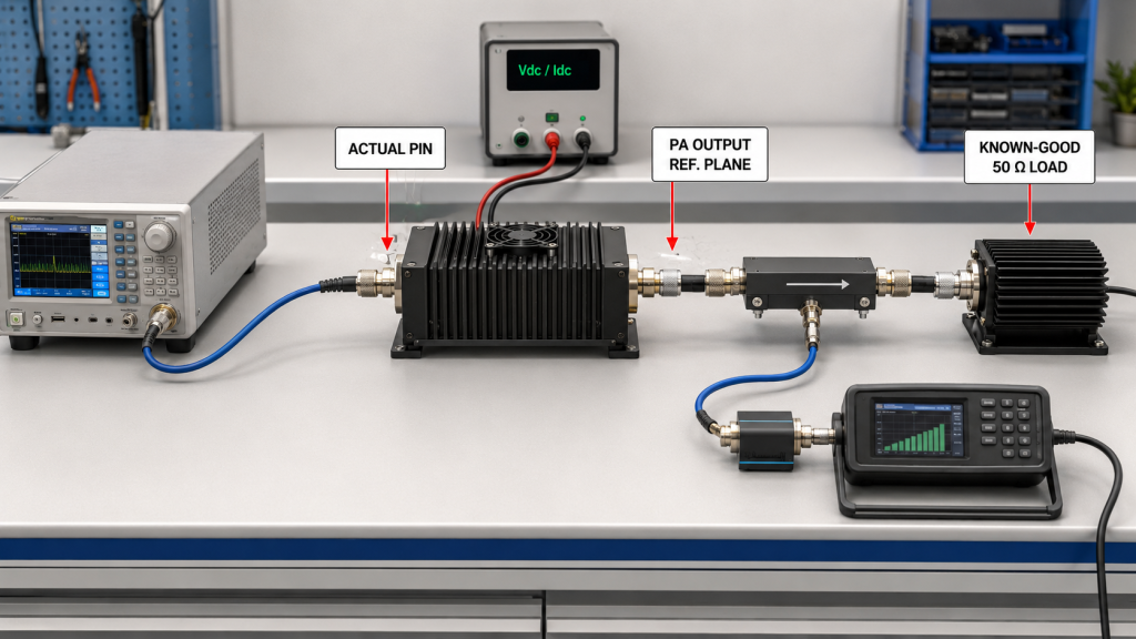
If the high-frequency reduction remains after these conditions are controlled, then the abnormal result exists within the PA-side or upstream test boundary and requires deeper diagnosis.
Possible investigation areas include:
- input-drive variation;
- measurement correction;
- intrinsic PA frequency response;
- PA-terminal voltage behavior;
- thermal state;
- protection back-off.
These mechanisms should not all be re-diagnosed inside this article.
When the affected frequency is also near the amplifier’s operating band edge, use the dedicated RF PA band-edge output diagnosis to separate Actual Pin, corrected PA-port Pout, intrinsic PA response, supply, thermal, load, and protection effects.
The handoff boundary is:
If the unacceptable result remains at the defined PA output reference plane under controlled operating and measurement conditions, the problem is no longer explained by the installed RF path alone.
5. What Evidence Should Be Saved Before the PA Is Replaced or Approved?
A useful high-frequency troubleshooting record should show where the abnormal difference occurred.
It should not rely on a collection of unrelated screenshots or readings from undefined planes.
Save, where applicable:
- delivered model and S/N;
- affected frequency;
- Actual Pin;
- corrected PA-port Pout;
- downstream measurement value;
- downstream power definition;
- PA output reference plane;
- downstream reference plane;
- frequency-specific path loss or correction;
- FWD / REV / VSWR and their sensing plane where relevant;
- Vdc / Idc where relevant;
- load condition;
- cooling and thermal state;
- protection status;
- installed RF-path configuration;
- corrective action;
- retest result.
The evidence should allow another engineer to answer three questions:
- Did the unacceptable high-frequency result already exist at the PA output reference plane?
- Did an additional abnormal difference appear only after the installed RF path was added?
- Were the compared measurements based on comparable operating conditions, defined reference planes, and the same power quantity?
Where wider swept-frequency verification is required before acceptance, use full-power RF PA test evidence rather than expanding this troubleshooting page into a complete acceptance procedure.
When the troubleshooting result affects unit-level acceptance or release, keep the record linked to the delivered S/N and the exact test configuration used for the final retest.
FAQ
Does a high-frequency output drop prove the RF PA is weak?
No. A lower high-frequency result does not identify the failing boundary by itself.
First separate Actual Pin, corrected PA-port Pout, the downstream measurement result, reference planes, path correction, and load condition. The PA should not be assigned as the cause unless the unacceptable result remains at the PA-side measurement boundary under comparable conditions.
Why can PA-port power pass while downstream RF power is too low?
The installed RF path introduces frequency-dependent insertion loss after the PA output.
If forward power measured at a defined downstream reference plane falls more than the verified path-loss budget predicts, the installed path becomes the next diagnostic boundary.
If mismatch is also present, reflected power must be evaluated separately before the difference is attributed to insertion loss.
What should be checked before replacing the PA?
Confirm Actual Pin, corrected PA-port Pout, the downstream power definition, both measurement reference planes, frequency-specific path correction, FWD / REV / VSWR where relevant, load condition, and applicable supply, thermal, and protection states.
Replacement should follow evidence showing that the unacceptable result remains inside the controlled PA test boundary rather than only appearing after the installed RF path is added.
Conclusion
A high-frequency output drop after installation should not be assigned to the RF PA until the failing measurement boundary has been identified.
If corrected PA-port Pout still meets the applicable requirement while a comparable downstream measurement falls outside the verified frequency-specific path budget or project limit, the investigation should move downstream of the PA reference plane.
The next step is to separate excessive insertion loss, mismatch, and measurement-definition errors before assigning a component-level cause.
If corrected PA-port Pout also fails under comparable Actual Pin, load, supply, thermal, measurement, and protection conditions, the diagnosis should return to the PA-side test boundary.
A higher REV-to-FWD relationship or worse VSWR should also be interpreted separately from insertion loss. Under a valid and consistent sensing boundary, it is consistent with increased mismatch, but it does not by itself prove which downstream component caused the condition.
Before approval or replacement, keep the affected frequency, Actual Pin, corrected PA-port Pout, downstream power definition, both reference planes, frequency-specific path correction, load condition, and relevant operating state traceable in the test record.
For a custom RF Power Amplifier Module, define the target high-frequency points, required PA-port output, downstream or antenna-input requirement where applicable, Actual Pin rule, installed RF path, load condition, duty cycle, cooling boundary, and required test evidence before approval.
Contact us with the target frequency range, output requirement, feeder length, antenna path, DC supply, cooling condition, and test-report requirements for your C-UAS RF PA project.