










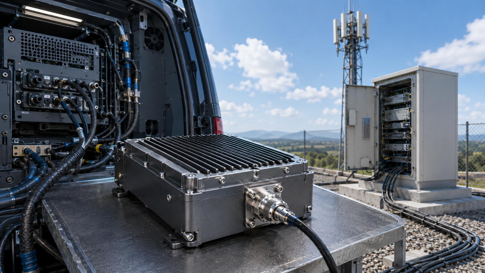
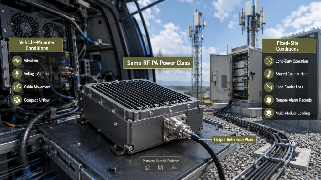
RF PA platform selection should not begin with wattage alone. A module with the same rated output can face very different mechanical, electrical, thermal, and RF-path conditions in a vehicle-mounted system and a fixed-site installation.
A vehicle platform may expose the RF PA to vibration, startup voltage changes, compact airflow, cable movement, and limited service space. A fixed-site system may require sustained operation, shared cabinet cooling, remote antenna feeders, outdoor interfaces, and reliable remote alarm records.
The same RF PA power class may fit both platforms, but the approval evidence should not be identical.
Before selecting RF Power Amplifier Modules, define the platform, required frequency points, output reference plane, duty cycle, 28V supply condition, cooling method, antenna path, protection behavior, and acceptance boundary.
1. Why Does Platform Type Change RF PA Approval?
An RF PA does not operate independently from the platform around it.
Its real behavior depends on:
- Input drive
- Operating frequency
- Duty cycle
- Module-terminal voltage
- Cooling
- Mechanical mounting
- RF cable routing
- Antenna load
- Control timing
- Protection logic
A vehicle-mounted and fixed-site system may use the same nominal PA output, but they rarely apply the same stress in the same way.
For example, assume both platforms require the same 100W-class module. The vehicle installation may have a short RF path but greater vibration, cable movement, and DC variation. The fixed-site installation may have stable mounting but a longer feeder path, higher cabinet heat accumulation, and longer operating periods.
The correct question is not:
Can this PA produce 100W?
It is:
Can this PA maintain the required output, protection behavior, and reporting under the approved platform conditions?
A general C-UAS RF PA selection workflow should first define the shared RF requirements, including frequency, output, duty cycle, control, cooling, antenna load, and protection. Platform review then adds the installation stresses that a common bench test does not represent.
“Vehicle-mounted” and “fixed-site” are not complete technical specifications. They identify typical risk priorities, but approval must still be based on measured conditions and defined acceptance limits.
The approval boundary should state:
- Where output power is measured
- Whether testing uses a dummy load or installed antenna path
- Whether the result is cold-state or hot-state
- Whether 28V is measured at the source or PA terminals
- Whether mechanical or outdoor conditions are included
- Whether several channels operate simultaneously
- How alarm, Reset, and recovery behavior are verified
- How evidence is linked to the module serial number
A module should not be approved from one short bench-output result.
2. What Must a Vehicle-Mounted RF PA Survive?
Vehicle-mounted systems usually combine mechanical movement, dynamic DC conditions, compact thermal design, and limited maintenance access.
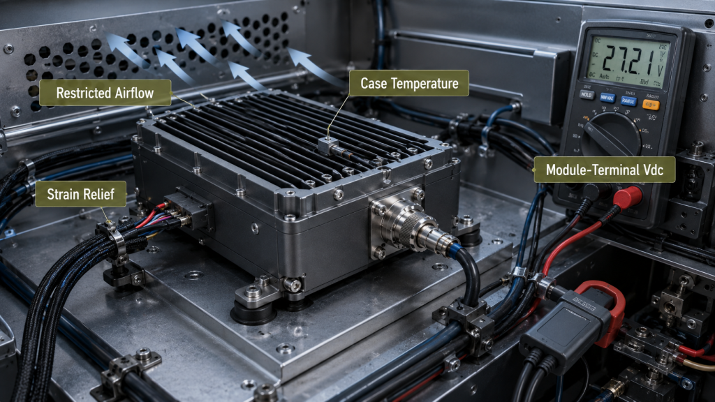
Mechanical and RF-interface stress
Vehicle movement can affect:
- PA mounting points
- RF connectors
- DC and control terminals
- Heavy cable assemblies
- Heatsink contact
- Fans and air ducts
Cable weight should not pull directly on RF or control connectors. The installation should define mounting orientation, fastener method, strain relief, cable support, bend radius, connector retention, and replacement access.
Acceptance should confirm stable output before, during where applicable, and after the approved vibration profile. This is important because an intermittent connector or cable fault may appear only while the platform is moving.
Vehicle 28V behavior
The source may be nominally 28V, but the PA may receive less after cables, switches, fuses, connectors, and shared vehicle loads are included.
The review should record:
- Source voltage
- Module-terminal voltage during RF output
- Full-load current
- Startup and enable behavior
- Shared-load condition
- Ground return quality
The most important value is the voltage available at the PA terminals while the module is producing the required RF output.
A dedicated vehicle DC supply margin review is useful when the installation includes long DC runs, shared branches, or significant startup variation.
Compact thermal conditions
Vehicle cabinets often have limited internal volume. Local PA temperature can rise because of restricted airflow, adjacent power electronics, short recirculation paths, dust, or blocked heatsink surfaces.
The module should be tested in its installed orientation and approved airflow condition. A short open-bench test does not prove vehicle suitability.
Vehicle approval evidence should include:
- Required output under the approved vehicle sequence
- Module-terminal Vdc and Idc
- Connector and cable retention
- Compact-cabinet hot-state behavior
- Required enable timing and state switching
- Alarm behavior during approved voltage variation
- Recovery after temporary events
- Clear module and channel identification
3. What Must a Fixed-Site RF PA Sustain?
Fixed-site systems may avoid continuous vehicle movement, but they often create longer operating periods, greater cabinet heat accumulation, remote RF paths, outdoor interfaces, and longer maintenance intervals.
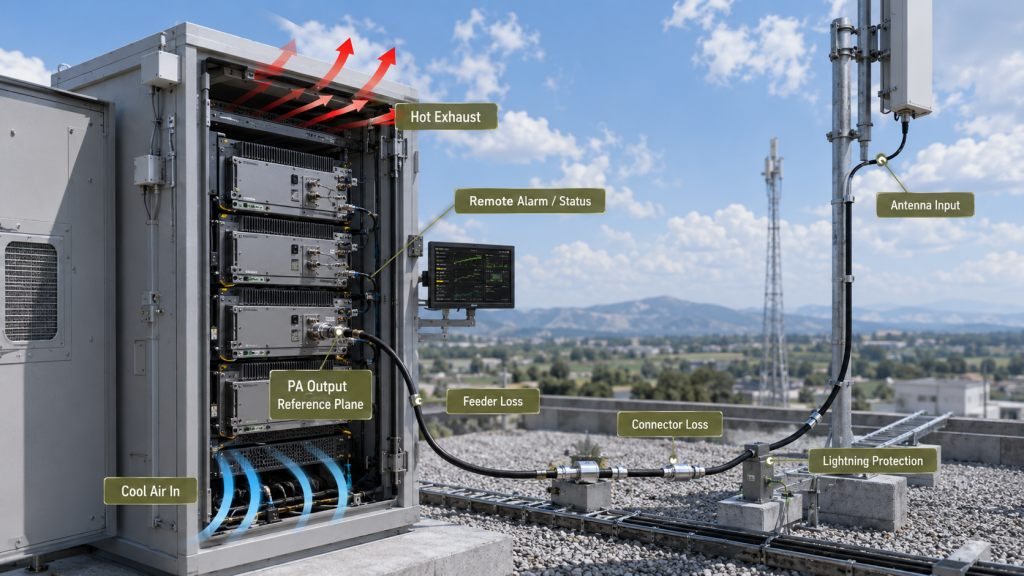
Sustained operation
A fixed-site PA should maintain the required result after the installation reaches thermal stability.
Acceptance should verify output at all required frequency points after:
- Thermal stabilization
- Shared cabinet heating
- Approved long-duty operation
- Repeated enable cycles
- Simultaneous-channel loading where applicable
The test record should include output, module-terminal Vdc and Idc, temperature, alarm state, and recovery behavior.
Shared cabinet heat
Fixed-site cabinets may contain several PA modules, SDR equipment, power supplies, RF switches, filters, and control electronics.
Cooling must reject the combined heat of the complete installation, not only one PA tested separately.
The review should confirm:
- Air inlet and exhaust paths
- Module spacing
- Fan direction
- Air bypass control
- Filter condition
- Cabinet ambient temperature
- Hot-air recirculation risk
The wider RF PA thermal design should be reviewed when several high-power modules share one enclosure.
Remote antenna paths
Fixed-site systems frequently place antennas away from the RF cabinet. This can introduce feeder loss, connector loss, cabinet feedthrough loss, lightning-protector loss, outdoor sealing requirements, and additional mismatch risk.
Rated output at the PA connector does not prove that the required power reaches the antenna.
The system should define:
- PA-output reference plane
- Antenna-input requirement
- Installed feeder length
- Cable type
- Loss by frequency
- Connector and transition count
- Antenna VSWR or Return Loss
For long or high-frequency routes, use a remote antenna RF PA sizing review before choosing a larger power class.
Fixed-site approval evidence should include:
- Output at all required frequency points after thermal stabilization
- Installed feeder loss where applicable
- Antenna-input power when required
- FWD, REV, and VSWR behavior
- Multi-module DC loading
- Cabinet airflow performance
- Long-duty protection and recovery
- Remote alarm records
- S/N-linked traceability
4. How Do Vehicle and Fixed-Site Requirements Compare?
The following matrix shows typical priorities, not exclusive boundaries. Any condition that exists in the real installation must be included in the acceptance plan.
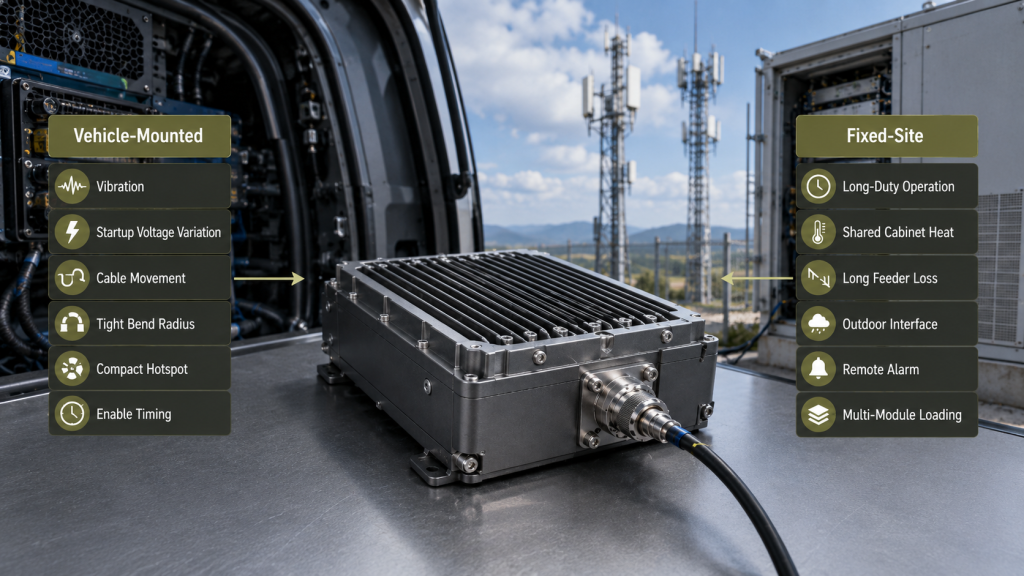
Vehicle-Mounted vs Fixed-Site Selection Matrix
| Selection Boundary | Typical Vehicle Priority | Typical Fixed-Site Priority |
|---|---|---|
| Mechanical condition | Vibration, shock, cable movement, connector strain | Long-term mounting stability, weathering, corrosion |
| 28V supply | Startup drop, transients, shared vehicle loads | Continuous current, shared bus loading, long distribution paths |
| Thermal condition | Compact hotspots and restricted airflow | Long-duty cabinet heat accumulation |
| RF path | Moving cables, tight bends, short jumpers | Longer feeders and greater transition loss |
| Grounding | Chassis continuity under movement | Long-term bonding and environmental stability |
| Duty cycle | Task-based, intermittent, or rapid state changes | Sustained, repeated, or multi-channel operation |
| Control behavior | Required enable timing during the vehicle sequence | Remote supervision, alarm logging, Reset, and recovery |
| Maintenance | Fast access and replacement | Remote diagnosis and longer service intervals |
| Main added test | Mechanical, dynamic DC, and compact hot-state testing | Long-duration hot-state and installed-path testing |
Can the same module fit both platforms?
Yes, when its confirmed limits support both installations.
The review should verify:
- Frequency compatibility
- Output at the required reference plane
- 28V terminal conditions
- Thermal performance
- Mechanical interfaces
- Antenna-path conditions
- Protection and recovery
- Platform-specific evidence
A different part number is not automatically required when the platform changes. The decision should depend on the confirmed mechanical, electrical, thermal, environmental, and interface limits.
Different connectors, mounting features, cooling structures, environmental requirements, or control interfaces may justify different module configurations even when the RF power class remains the same.
5. What Evidence Must Change with the Platform?
Both platforms should first pass the same baseline RF, DC, thermal, protection, control, and traceability checks.
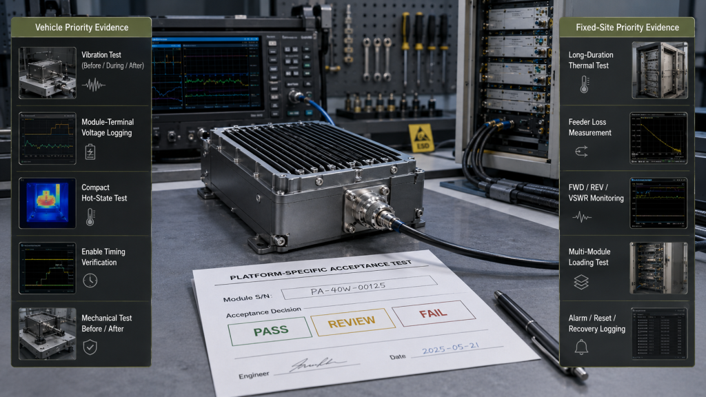
The common baseline should verify:
- Required frequency points
- Input drive
- Output at the defined reference plane
- Module-terminal Vdc and Idc
- Temperature
- Alarm and protection behavior
- Reset and recovery
- Module S/N
- Test setup and operating condition
Platform-specific testing should then add the stresses that are not represented by the common bench test.
Platform-Specific Acceptance Evidence
| Evidence Item | Vehicle-Mounted Addition | Fixed-Site Addition |
|---|---|---|
| Output power | Verify during the approved vehicle sequence and after mechanical stress | Verify after thermal stabilization and long-duty operation |
| Vdc and Idc | Record startup, enable, and shared vehicle loads | Record continuous current and shared cabinet bus loading |
| Mechanical evidence | Mounting, strain relief, connector retention | Long-term mounting, sealing, and corrosion control |
| Thermal evidence | Local hotspot and compact airflow | Cabinet heat accumulation and multi-module airflow |
| RF-path evidence | Cable movement, bends, and connector strain | Feeder loss, lightning protection, and remote antennas |
| Protection evidence | Response to approved voltage and movement-related events | Warning, foldback, shutdown, and recovery during long-duty operation |
| Control evidence | Required enable timing and state switching | Remote status, alarm, Reset, and recovery records |
| Traceability | Module and vehicle position | Module, cabinet, channel, feeder, and antenna identity |
Evidence should follow the dominant failure risk
A vehicle test that records only long-duration temperature may miss startup voltage drop, cable strain, connector movement, or intermittent control faults.
A fixed-site test that records only vibration may miss feeder loss, cabinet heat accumulation, simultaneous-module loading, or long-duty foldback.
Each result should use defined acceptance criteria.
Pass
- Output remains within tolerance
- Module-terminal voltage remains acceptable
- Temperature stays inside the approved limit
- Alarm and recovery behavior match the defined logic
- No unexpected mechanical or RF-interface fault appears
Review
- Output remains usable but margin is reduced
- One condition approaches its approval boundary
- Cooling, cable, DC, or layout changes may be required
- Additional repeatability evidence is needed
Fail
- Output falls below the reference-plane requirement
- Protection or alarm behavior is incorrect
- Recovery is unstable
- Mechanical or RF interfaces become unreliable
- Evidence cannot be linked to the approved module and test condition
6. What Platform Information Should Be Added to the RFQ?
Frequency, output reference plane, input drive, duty cycle, antenna load, control interface, and baseline protection requirements should already be defined by the main RF PA selection process.
The platform RFQ should add only the installation-specific information needed to build the correct test boundary.
Vehicle-Specific RFQ Additions
- Vehicle type and mounting location
- Mounting orientation
- Vibration and shock profile
- DC source range
- Startup voltage behavior
- Shared vehicle loads
- DC cable length
- Chassis-ground arrangement
- Cable support and strain relief
- Available airflow
- Nearby heat sources
- Required enable sequence
- Replacement access
- Vehicle-position identification
Fixed-Site RFQ Additions
- Indoor, outdoor, or protected-cabinet installation
- Cabinet dimensions
- Cooling and airflow method
- Number of simultaneous modules
- Shared 28V bus condition
- Installed feeder length
- Cable type and loss by frequency
- Cabinet feedthroughs
- Lightning protection
- Antenna VSWR or Return Loss
- Outdoor sealing and corrosion conditions
- Long-duty test duration
- Remote alarm and Reset access
- Maintenance interval
- Cabinet, channel, feeder, and antenna identification
Required acceptance output
The final platform acceptance package should identify:
- Module S/N
- Platform and installation position
- Test reference plane
- Frequency and duty condition
- Module-terminal Vdc and Idc
- Output and temperature
- Alarm and protection state
- Platform-specific stress
- Recovery result
- Pass, Review, or Fail decision
FAQ
Can the same RF PA module be used in both vehicle-mounted and fixed-site systems?
Yes, when its confirmed RF, DC, thermal, mechanical, control, and environmental limits support both installations. The module may be the same, but the acceptance evidence should reflect each platform.
Is a fixed-site RF PA easier to integrate than a vehicle-mounted PA?
Not necessarily. Fixed-site systems may avoid continuous vehicle vibration, but they can introduce long-duty heating, remote feeder loss, outdoor interfaces, shared cabinet loads, and longer maintenance intervals.
Should both platforms use the same acceptance test?
They should share the same baseline RF, DC, thermal, protection, control, and traceability tests. Each platform should then add the mechanical, electrical, environmental, and RF-path tests that match its real installation risks.
Conclusion
RF PA platform selection should compare more than rated wattage.
Vehicle-mounted systems usually place greater emphasis on mechanical stress, dynamic 28V behavior, compact thermal conditions, cable movement, and service access. Fixed-site systems usually place greater emphasis on sustained output, cabinet heat, remote RF paths, outdoor interfaces, and long-term alarm visibility.
These are typical priorities, not exclusive boundaries. The final approval plan must reflect every condition that exists in the real installation.
RF SKYPOWER can support early platform review before RF PA approval. Submit the installation type, frequency points, required output reference plane, duty cycle, 28V supply condition, cabinet dimensions, cooling method, antenna route, vibration or outdoor limits, protection requirements, and acceptance-report format.
Contact RF Engineering Team to compare vehicle-mounted and fixed-site requirements before the module, cabinet, DC path, and antenna layout are locked.