


A reliable RF Power Amplifier keeps output power, gain, bandwidth, signal quality, and thermal behavior stable when real operating stress begins. In a counter-UAS, EW, communication, or perimeter-defense system, one weak amplifier can cause short coverage, unstable suppression, failed acceptance testing, or emergency redesign. A properly engineered RF Power Amplifier solves this by combining verified output power, gain flatness, controlled distortion, efficient heat transfer, VSWR protection, and repeatable factory testing. Here’s the deal: reliability is not a single specification; it is the result of every RF, electrical, thermal, and manufacturing detail working together.
In a typical border, airport, or high-security facility project, you may see a sample pass a short bench test, then fail during antenna matching, cabinet heat buildup, or full-band deployment. That pain often comes from buying a power number instead of checking full RF behavior. This article breaks down what you should verify before you design, purchase, or integrate an RF Power Amplifier into a serious system.
1. What RF Power Amplifier Specs Should You Check?
An RF Power Amplifier parameter set defines how much signal power you can deliver, how clean that signal remains, and how stable your system behaves under real operating stress. Output power, gain, efficiency, linearity, bandwidth, noise figure, impedance matching, protection logic, and thermal design work together rather than separately. What’s the real story? A module can look strong on a single datasheet line while still failing in a wideband platform, especially when antenna VSWR, ambient heat, and continuous duty cycle enter the picture.

What should you check before trusting a datasheet?
You should check every parameter under conditions close to your real application. A counter-drone cabinet, fixed airport perimeter node, or vehicle-mounted system rarely operates under perfect lab comfort. This is where it gets serious: you need measured behavior across frequency, power, load, and temperature.
- Rated output power under CW or pulsed operation
- Gain and gain flatness across full band
- Linearity under modulation or multi-carrier signals
- Efficiency at rated output and backed-off output
- VSWR tolerance, thermal limits, and alarm logic
- Mechanical fit, connector layout, and control interface
| Parameter | What It Controls | Why You Care |
|---|---|---|
| Output power | RF energy delivered | Coverage and link margin |
| Gain | Signal amplification ratio | Driver-stage planning |
| Gain flatness | Band-to-band consistency | Stable wideband output |
| Linearity | Signal purity | Lower distortion risk |
| Efficiency | DC-to-RF conversion | Heat and power budget |
| Thermal design | Long-duty survival | Fewer field shutdowns |
Key Takeaway: You should judge an RF Power Amplifier as a complete RF subsystem, not as a wattage label. Use this table as a pre-purchase checklist before you approve samples or release batch orders.
2. How to Check RF Power Amplifier Output Power
An RF Power Amplifier output power matters because it determines how much usable RF energy reaches your antenna or load after losses. In practical systems, output power affects range, suppression strength, link budget, and margin against cable loss. But here’s the catch: more watts do not automatically mean better performance. If output power comes with severe compression, heat rise, spurious emissions, or mismatch sensitivity, your system may lose reliability right when it needs strength most.
How should you size output power?
You should size output power from system need rather than supplier hype. A low-band module for 30–512MHz coverage may face different antenna size, cable loss, and duty-cycle demands than a 2–6GHz module in a compact cabinet. Here’s what matters now: your selected power level must survive real load behavior.
- Start with required field coverage or link budget
- Add cable, connector, filter, and antenna mismatch losses
- Check rated power across full frequency range
- Confirm CW or pulsed duty requirements
- Reserve margin for heat, aging, and batch variance
| Output Power Term | Meaning | Buyer Risk If Ignored |
|---|---|---|
| Rated power | Declared working output | May only apply at one frequency |
| Saturated power | Maximum compressed output | Can distort signals |
| P1dB | 1 dB compression point | Shows usable linear range |
| CW power | Continuous operation output | Exposes thermal weakness |
| Peak power | Short burst output | Often misleading alone |
Key Takeaway: You should treat output power as a verified operating condition, not a decorative number. Ask for power curves across frequency before using any RF Power Amplifier in a field-grade design.
3. How Does RF Power Amplifier Gain Affect Signal Control?
An RF Power Amplifier gain affects signal control by deciding how much input drive becomes usable output power. Gain lets you match a signal source, SDR exciter, driver stage, or control board with a final PA stage. You might be wondering: why not simply choose high gain every time? Excessive gain can amplify noise, create oscillation risk, reduce control margin, and make your RF chain harder to tune during integration.
What gain behavior should you demand?
You should demand stable gain across target frequency bands rather than one attractive gain value at one test point. In wideband systems, gain flatness often matters as much as gain level. Ready for the practical part? flat gain helps you avoid weak band edges and overpowered band centers.
- Check small-signal gain across full band
- Confirm large-signal gain near rated output
- Review gain compression under load
- Compare gain variation at temperature extremes
- Match gain with driver source output
| Gain Factor | Strong Design Signal | Weak Design Signal |
|---|---|---|
| Gain level | Matches drive budget | Needs extra driver stages |
| Gain flatness | Stable across band | Power dips at band edges |
| Compression | Predictable roll-off | Sudden output collapse |
| Temperature drift | Limited variation | Retuning needed in field |
| Batch consistency | Repeatable units | Sample differs from batch |
Key Takeaway: You should use gain data to protect your control margin. A stable RF Power Amplifier gives you cleaner sizing from exciter output through final antenna delivery.
4. How to Judge RF Power Amplifier Gain Flatness
An RF Power Amplifier gain flatness matters because wideband systems must deliver predictable output across more than one frequency point. If a module claims 300–1200MHz support but drops heavily around 868MHz, 915MHz, or 1.2GHz, your real coverage can become uneven. Here’s the deal: full-band work needs full-band proof. A single center-frequency screenshot cannot show whether your system will survive agile links, multi-band planning, or acceptance testing.
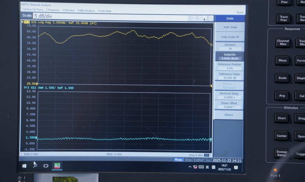
How can you detect poor flatness early?
You can detect poor flatness by requesting swept-frequency data and testing with realistic drive levels. Flatness should be checked under both small-signal and near-rated output conditions because compression can hide problems. This is where buyers save money: early curve review prevents cabinet redesign later.
- Ask for gain versus frequency plots
- Compare output power at band edges
- Test with target cable and antenna path
- Check ripple from filters or matching networks
- Confirm repeatability across samples
| Flatness Issue | Field Symptom | Procurement Question |
|---|---|---|
| Edge roll-off | Weak coverage near band limit | Is full-band power verified? |
| Gain ripple | Uneven suppression or link quality | What causes ripple? |
| Batch variation | Different unit behavior | Is BOM locked? |
| Thermal drift | Output changes after warm-up | Was hot testing done? |
| Overdrive masking | Strong test at one point | Was sweep done near rated power? |
Key Takeaway: You should demand gain flatness evidence when buying a wideband RF Power Amplifier. Curve shape tells you more than a single headline gain value.
5. What Defines RF Power Amplifier Linearity?
An RF Power Amplifier linearity links directly to distortion because a nonlinear PA creates unwanted frequency products when signal level rises. In communication, radar, and controlled RF systems, distortion can spread energy into adjacent channels, worsen modulation quality, or disturb nearby equipment. What’s the catch? a module can deliver rated watts while producing poor spectral behavior. That means you may pass a power check yet fail signal-quality or compliance review.
What linearity metrics should guide your review?
You should review P1dB, IP3, ACPR, EVM, harmonic levels, and spurious output based on your application. A jammer module, communication transmitter, or test source may require different purity rules. Here’s why this matters: distortion can become a system-level problem rather than a PA-only problem.
- Use P1dB for compression awareness
- Use IP3 for intermodulation risk
- Use ACPR for adjacent-channel leakage
- Use harmonic data for filtering needs
- Use spectrum plots for real visual proof
| Linearity Metric | What It Shows | Why It Helps You |
|---|---|---|
| P1dB | Compression point | Defines usable output headroom |
| IP3 | Intermodulation behavior | Helps multi-tone planning |
| ACPR | Adjacent leakage | Supports channel purity |
| EVM | Modulation quality | Protects data integrity |
| Harmonics | Unwanted multiples | Guides filter design |
Key Takeaway: You should never separate power from spectral quality. A professional RF Power Amplifier must deliver usable watts with controlled distortion.
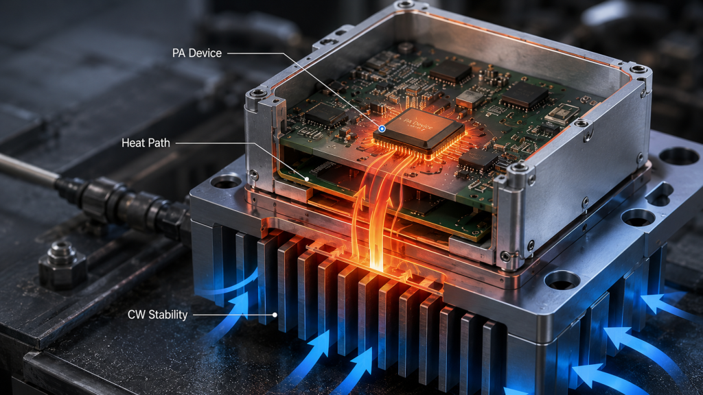
6. What Affects RF Power Amplifier Thermal Stability?
An RF Power Amplifier efficiency shapes thermal risk because every watt not converted into RF output becomes heat inside your cabinet. Low efficiency increases DC supply demand, heat sink burden, fan load, and long-duty stress. This is where it gets interesting: a PA with lower rated output but higher efficiency may outperform a hotter high-watt design during long operation. Field systems care about sustained behavior, not only short lab bursts.
How should efficiency be judged?
You should judge efficiency at rated output, backed-off output, target frequency points, and real ambient temperature. Power-added efficiency can shift across band and operating class. Here’s the practical angle: efficiency data helps you size heat sinks, DC feeds, batteries, and cabinet airflow.
- Review drain efficiency and PAE
- Measure efficiency at band edges
- Check backed-off efficiency for linear modes
- Confirm thermal rise during CW operation
- Match DC input capacity with RF output goal
| Efficiency Condition | What To Measure | Design Impact |
|---|---|---|
| Rated output | DC power versus RF power | Supply sizing |
| Back-off point | Efficiency below peak | Linear operation cost |
| Hot ambient | Efficiency after heat soak | Field stability |
| Band edge | Efficiency variation | Wideband reliability |
| Continuous duty | Heat rise over time | Cabinet cooling plan |
Key Takeaway: You should connect efficiency directly with thermal planning. A high-efficiency RF Power Amplifier reduces hidden pressure on power supply, enclosure, and service life.
7. How Does RF Power Amplifier Noise Figure Affect Signals?
An RF Power Amplifier noise figure affects signals by adding unwanted noise that reduces signal clarity in sensitive receive or transceiver paths. Although final-stage power amplifiers often focus on output power, noise still matters in compact RF systems, repeaters, and mixed transmit-receive architectures. You might be asking: does noise figure matter for every PA? Not equally. It matters most when weak signals, receiver sensitivity, or shared RF chains sit near amplifier stages.
Where does noise figure become a problem?
Noise figure becomes a problem when a system must preserve weak signal detail before processing. If a noisy RF stage enters early in a receive chain, later gain cannot fully repair lost signal-to-noise ratio. Here’s the buyer lesson: match noise requirements with chain position.
- Receiver front ends need low noise figure
- Driver stages should avoid unnecessary noise rise
- High-gain chains can amplify unwanted noise
- Transceiver designs need careful isolation
- System noise budget should be calculated early
| System Location | Noise Concern | Practical Review |
|---|---|---|
| LNA/front end | Weak signal loss | Demand low NF data |
| Driver stage | Noise multiplication | Check gain-noise balance |
| Final PA | Less sensitive usually | Watch spurious noise floor |
| Transceiver cabinet | Coupling risk | Review shielding layout |
| Test platform | Measurement purity | Use clean signal sources |
Key Takeaway: You should place noise figure in system context. A suitable RF Power Amplifier protects signal quality when receiver sensitivity or mixed RF architecture matters.
8. Why Do RF Power Amplifier Frequency and Bandwidth Matter?
An RF Power Amplifier frequency range and bandwidth matter because your module must perform where your target signals actually operate. A 30–512MHz system faces different matching, antenna, and enclosure constraints than a 2000–6000MHz system. Here’s the real issue: wide frequency coverage without verified output can create blind spots. For counter-UAS or EW platforms, those blind spots may appear exactly where agile protocols move.
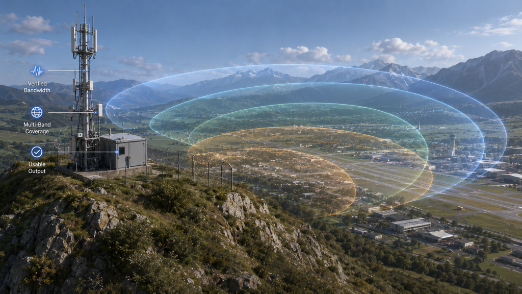
How should you match band coverage to application?
You should match band coverage to threat profile, communication band, antenna architecture, and installation type. Narrowband modules can give strong focused performance, while wideband modules reduce part count and cover moving signals. Ready for the field view? wideband convenience must still pass sweep testing.
- Use 30–512MHz for low-band tactical links
- Use 300–1200MHz for mid-low FPV/control bands
- Use 300–1700MHz or 300–2700MHz for broader planning
- Use 2000–6000MHz for high-band drone data links
- Confirm antenna and filter compatibility for each band
| Frequency Choice | Typical Design Goal | Main Risk |
|---|---|---|
| Narrowband | Higher focused performance | Limited coverage |
| Wideband | Multi-band flexibility | Flatness challenges |
| Low band | Longer wavelength coverage | Larger antennas |
| Mid band | FPV/control link planning | Edge roll-off |
| High band | GHz protocol coverage | Higher loss and routing care |
Key Takeaway: You should choose frequency coverage from real mission signals, not vague “full band” claims. A qualified RF Power Amplifier must prove usable power across its declared bandwidth.
9. Why Are RF Power Amplifier Matching and VSWR Vital?
An RF Power Amplifier matching and VSWR behavior matter because reflected power can reduce output, heat components, trigger protection, or damage the PA stage. Most RF systems assume a 50-ohm environment, yet real antennas, cables, filters, and connectors shift under installation stress. What’s the hidden trap? a module that works on a perfect dummy load may struggle when connected to a field antenna on a tower, vehicle, or cabinet.
What matching checks reduce field failure?
Matching checks reduce field failure by catching impedance problems before they reach live operation. You should review return loss, VSWR tolerance, reflected-power alarm thresholds, and protection recovery behavior. Here’s what separates factory work from guesswork: the PA should protect itself without becoming unstable.
- Measure antenna VSWR across frequency
- Test with real cable length and connectors
- Confirm reflected-power protection behavior
- Check output under mismatch conditions
- Review recovery after alarm release
| Matching Item | Good Sign | Risk Sign |
|---|---|---|
| Return loss | Low reflection | Poor power transfer |
| VSWR tolerance | Stable under mismatch | Sudden shutdown |
| Protection logic | Controlled power reduction | Burnout risk |
| Cable quality | Repeatable readings | Random output drift |
| Antenna tuning | Band-aligned behavior | Field blind spots |
Key Takeaway: You should test matching as a system condition. A rugged RF Power Amplifier must tolerate imperfect loads while protecting output devices and mission uptime.
10. How to Verify RF Power Amplifier Stability
An RF Power Amplifier stability should be verified through swept-frequency testing, load variation, thermal cycling, vibration, long-duty burn-in, and batch-level inspection. Stability covers more than “it powers on.” It means no self-oscillation, no thermal runaway, no uncontrolled gain drift, and no sudden failure during field stress. This is where procurement gets serious: stable samples are useful only when production units match them.
What proves stability before deployment?
Stability proof should include lab reports, serial-number records, burn-in results, and full-band measurement data. A source factory can connect engineering, SMT, CNC enclosure work, and QA under one workflow. Here’s the useful part: traceable testing helps you defend your selection during internal review, government acceptance, or integrator qualification.
- Full-band power and gain sweeps
- Thermal rise test under rated load
- VSWR alarm and recovery test
- Vibration and transport stress check
- Serial-number-linked inspection reports
| Verification Step | What It Catches | Value For You |
|---|---|---|
| Sweep testing | Band-edge weakness | Better acceptance confidence |
| Burn-in | Early component defects | Lower field failure risk |
| Thermal profiling | Hotspot issues | Smarter cabinet design |
| VSWR testing | Mismatch weakness | Safer antenna integration |
| Batch inspection | Production drift | Repeatable delivery |
Key Takeaway: You should verify stability before deployment rather than after a failed field trial. A properly validated RF Power Amplifier turns procurement risk into controlled engineering evidence.
Final Engineering Note
You have now covered output power, gain, gain flatness, linearity, efficiency, noise figure, operating frequency, bandwidth, matching, VSWR, stability, and thermal management. These specs help you separate a reliable RF Power Amplifier from a risky power module that only looks strong on paper. Here’s the final word: mission-grade RF design starts with measured truth, not sales claims.
If your team needs factory-direct RF modules, wideband frequency planning, thermal structure review, or integration support for counter-UAS and critical infrastructure systems, contact us today. We build RF cores for engineers who cannot afford blind spots, batch surprises, or unstable field behavior. Our position is simple: mission-critical airspace protection deserves RF hardware proven from lab bench to deployment site.
FAQ
Can I choose an RF Power Amplifier by wattage alone?
No, wattage alone gives an incomplete picture. You also need gain flatness, efficiency, linearity, VSWR behavior, thermal stability, and frequency-band proof because each factor affects field performance.
What’s the best RF Power Amplifier for wideband systems?
The best choice is a module verified across your full working band. A wideband RF Power Amplifier should show swept power, gain flatness, efficiency, and thermal data rather than one center-frequency result.
How do I know if an RF Power Amplifier will overheat?
You know by reviewing CW burn-in data, thermal resistance, case temperature rise, airflow needs, and power-back-off logic. Short bench tests rarely reveal long-duty heat behavior.
Can I use one RF Power Amplifier across many bands?
Yes, if the module has verified wideband performance and your antenna, filters, cables, and matching network support those bands. Without full-chain matching, wideband claims can lose value quickly.
How do I know if a supplier can support integration?
You know by checking whether they provide direct RF engineer access, VNA or spectrum testing, serial-number reports, controlled BOM, and batch validation. Real support comes from engineering control, not message forwarding.