


Many buyers ask the same question during RF Power Amplifier system selection: is one 300W module better than three 100W modules? The answer depends on what problem the system is trying to solve. If the problem is not enough single-path output, a higher-power module may be the right answer. If the problem is mission interruption after one module alarm, derating event, maintenance action, or failure, redundancy becomes the more important design question.
Higher RF power increases output capacity, but it does not remove single-point failure risk. In a fixed-site C-UAS system, an airport perimeter cabinet, a border node, or a critical infrastructure platform, one unavailable RF path may affect more than a number on a test report. It may decide whether the mission continues at all.
For RF Power Amplifier modules used in C-UAS integration, redundancy should not be treated as simply “adding more hardware.” It is a system architecture decision involving power margin, thermal load, 28V supply distribution, protection feedback, frequency priority, maintenance windows, and acceptable degraded operation.
The real question is not whether redundancy is always better. The real question is whether your mission can continue when one RF path becomes unavailable.
1. How to Compare RF Power Amplifier Redundancy
One larger RF Power Amplifier is not always safer because higher output power and higher system availability are different engineering goals. A single 300W module may deliver more power than one 100W module, but it can still create a concentrated failure point. If that one module overheats, alarms, loses supply stability, or needs replacement, the whole RF path may stop.
Here’s the engineering point: power capacity tells you how much RF output a path can produce, while redundancy tells you what the system can still do after one part becomes unavailable. A larger module may solve a weak output problem. It does not automatically solve mission continuity, fault isolation, or maintenance risk.

What Should You Separate Before Selection?
You should separate output capacity from mission continuity before choosing the architecture. This prevents a buyer from solving a system availability issue with only a larger wattage label.
- Do you need more RF output?
- Do you need operation after one module fault?
- Do you need easier module replacement?
- Do you need reduced downtime during service?
- Do you need a simpler RF chain?
If the answer is mainly “more output,” then higher power may be reasonable. If the answer is “the mission cannot stop,” the discussion should move toward redundancy.
Key Takeaway: This section helps you avoid treating more watts as the answer to every RF system risk. If the real problem is downtime, redundancy should be evaluated before simply increasing module power.
| Customer Question | Better Starting Point |
|---|---|
| We need stronger single-path output | Higher-power module |
| We need operation after one module alarm | Redundancy design |
| We need to compensate feeder loss | Power margin review |
| We need easier module replacement | Modular redundancy |
| We need the simplest RF chain | Single-module architecture |
A larger module can be the right answer, but only when the real problem is output capacity rather than interruption risk.
2. When Is a Single High-Power RF Power Amplifier Still Better?
A single high-power RF Power Amplifier is still better when the system mainly needs stronger output, simpler control, lower module count, and acceptable downtime. Redundancy is not a universal upgrade. It adds cabinet space, wiring, DC distribution, control logic, switching rules, test points, and maintenance planning.
This is where a professional selection process must avoid one-sided thinking. Some systems do not need redundancy because their mission profile is short, their duty cycle is low, their site is easy to access, or a temporary stop does not create serious operational loss. In those cases, one well-selected higher-power module can be cleaner than a multi-module architecture.

Which Conditions Favor One Larger Module?
A single-module approach is often reasonable when simplicity and single-path output matter more than continuous availability. It is also easier to validate when the RF path is short and the operating profile is predictable.
- The platform has limited cabinet space.
- The RF path is simple and direct.
- The mission allows planned downtime.
- The system has fast on-site maintenance access.
- The buyer needs stronger single-path output.
- The control system cannot support failover logic.
- Spare equipment is handled at whole-unit level.
The practical risk is not the single module itself. The risk appears when the buyer assumes “more power” also means “less mission risk.”
Key Takeaway: This section helps you avoid overbuilding redundancy when the real requirement is a stronger and simpler RF path.
| Condition | Single High-Power Module Fit |
|---|---|
| Short test operation | Strong fit |
| Low-duty mobile use | Often suitable |
| Fast local maintenance | Often suitable |
| Mission must not stop | Weak fit |
| Remote fixed-site operation | Needs review |
| Multi-channel continuity need | Usually weak fit |
A single high-power design is not a lower-grade choice; it is the right choice when the system can accept its interruption boundary.
3. What Makes RF Power Amplifier Redundancy Necessary
RF Power Amplifier redundancy becomes necessary when one local module problem cannot be allowed to become a full system interruption. This usually happens in long-duty, fixed-site, remote, high-security, or mission-critical C-UAS deployments where service access is limited and partial capability is better than total shutdown.
Here’s the field reality: redundancy is not designed because engineers expect modules to fail constantly. It is designed because serious systems must define what happens when something does fail. A module may enter temperature protection, show reflected-power alarm, lose stable supply, or require replacement. Without redundancy, the answer may be full stop.

What Triggers a Redundancy Review?
A redundancy review should begin when downtime, delayed maintenance, or single-point failure carries operational cost. The trigger is not only technical; it is also mission and service related.
- The site must operate continuously or for long watch periods.
- A single RF path failure would remove a critical capability.
- Maintenance access is slow, restricted, or expensive.
- The system must wait safely until the next service window.
- Certain frequency bands or directions must remain available.
- The operator needs clear fault isolation.
- Downtime cost is higher than added architecture cost.
In C-UAS and electronic security systems, this difference matters. A temporary test platform can stop. A fixed perimeter site may not have that luxury.
Key Takeaway: This section helps you identify when redundancy is a mission-continuity requirement rather than an optional upgrade.
| Redundancy Trigger | Why It Matters |
|---|---|
| No tolerance for full stop | Keeps partial capability available |
| Remote maintenance | Lets system wait for service |
| Critical channel priority | Protects key bands or sectors |
| Long-duty operation | Local faults become more likely |
| Limited service window | Module isolation saves time |
| High downtime cost | Extra architecture may be justified |
Redundancy becomes serious when interruption risk becomes more important than the simplicity of one larger module.
4. How to Plan RF Power Amplifier Degraded Operation
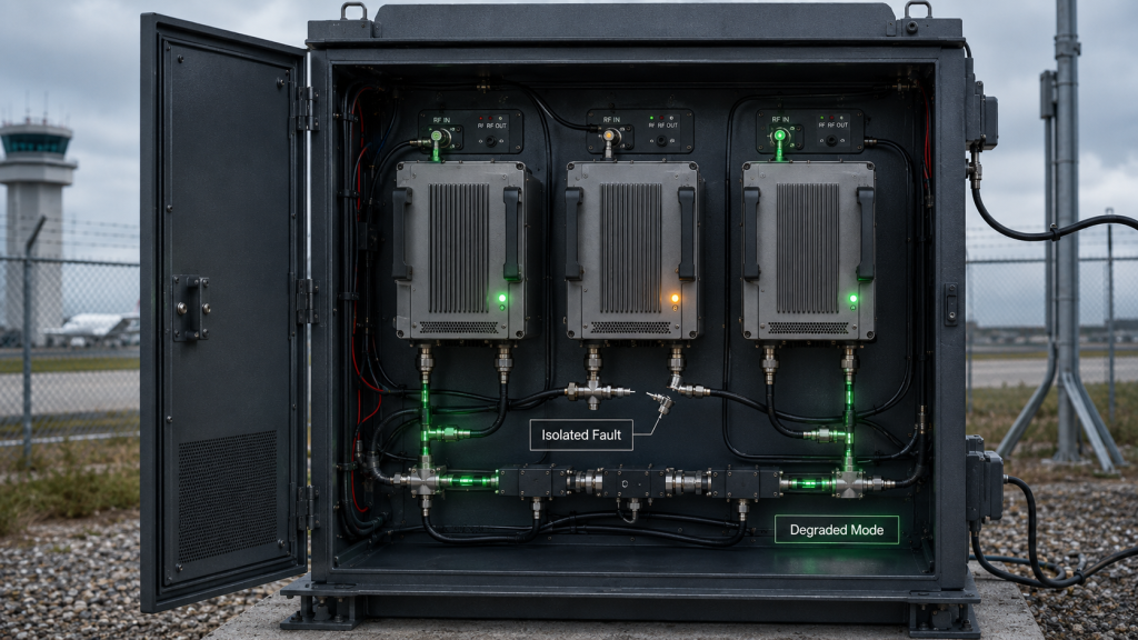
Redundancy keeps a C-UAS mission running by allowing the RF Power Amplifier system to shift from full operation to controlled degraded operation instead of stopping completely. The most important word is controlled. A redundant system should know which module has a problem, which paths remain available, which bands or sectors are still active, and what action the operator should take.
This is where system integrators should pay attention. Redundancy is not simply placing another module in the cabinet. It requires state feedback, alarm interpretation, operating priority, and a defined degraded mode. If the system cannot decide what to do after one module alarm, the extra hardware may not create real availability.
What Does Controlled Degradation Require?
Controlled degradation is useful only when it is designed before the fault occurs. A pile of extra modules is not redundancy unless the system knows how to use them.
- Keep unaffected frequency bands active.
- Reduce output but maintain partial coverage.
- Isolate one faulty module or channel.
- Switch priority to critical bands or directions.
- Alert the operator without shutting down everything.
- Log the event for later maintenance.
- Wait safely until the next service window.
For low-altitude security and C-UAS system integration, this is often more valuable than chasing the largest single wattage number. A mission may accept reduced capability for a limited time. It may not accept silence from the whole RF chain.
Key Takeaway: This section helps you define redundancy as a controlled operating mode, not just extra hardware in the cabinet.
| System State | Without Redundancy | With Planned Redundancy |
|---|---|---|
| One module overheats | Whole path may stop | Affected path can reduce or isolate |
| One band needs service | Band may be lost | Other bands can remain active |
| One sector has a fault | Coverage gap may be total | Other sectors continue |
| Maintenance is delayed | Mission risk increases | System can wait in degraded mode |
| Operator receives alarm | Response may be unclear | Action can follow defined logic |
The value of redundancy is controlled continuity when perfect operation is no longer available.
5. What Happens When RF Power Amplifier Modules Alarm
When one RF Power Amplifier module alarms, the system must decide whether to reduce output, isolate the module, switch load, keep other paths active, or shut down the affected chain. In a non-redundant architecture, the choice is often simple but harsh: the path stops. In a redundant architecture, the response should be more selective.
The practical risk is clear: alarms do not always come from the same source. A temperature alarm, VSWR alarm, voltage alarm, and current anomaly mean different things. A redundant system should not treat every alarm as a reason to stop everything, but it also should not blindly continue operation without protecting the affected RF chain.

Which Alarm Decisions Must Be Defined?
Protection logic should translate module status into system action. This keeps the response predictable during real faults.
- Is this alarm local to one module?
- Does it indicate a shared supply problem?
- Is the antenna path unsafe?
- Can the affected module reduce output?
- Can other modules continue safely?
- Should the system enter degraded mode?
- Should the operator receive a service warning?
This is why RF Power Amplifier protection feedback and control interfaces are not just convenience features. In redundant systems, protection feedback becomes part of system behavior.
Key Takeaway: This section helps you prevent a redundant system from behaving like a larger single point of confusion during faults.
| Alarm Type | Possible Meaning | System Decision Needed |
|---|---|---|
| Temperature alarm | Local heat stress | Reduce load or isolate module |
| VSWR alarm | Load mismatch | Protect affected RF chain |
| Voltage alarm | Supply instability | Check shared DC risk |
| Current anomaly | Electrical or load issue | Identify module or path |
| Module offline | Lost path | Enter degraded mode |
| Repeated fault | Persistent risk | Lock out and request service |
A module with VSWR, temperature, and voltage protection can protect itself. The full C-UAS system still needs to know what that protection means for the mission.
6. How to Review RF Power Amplifier Maintenance Risk
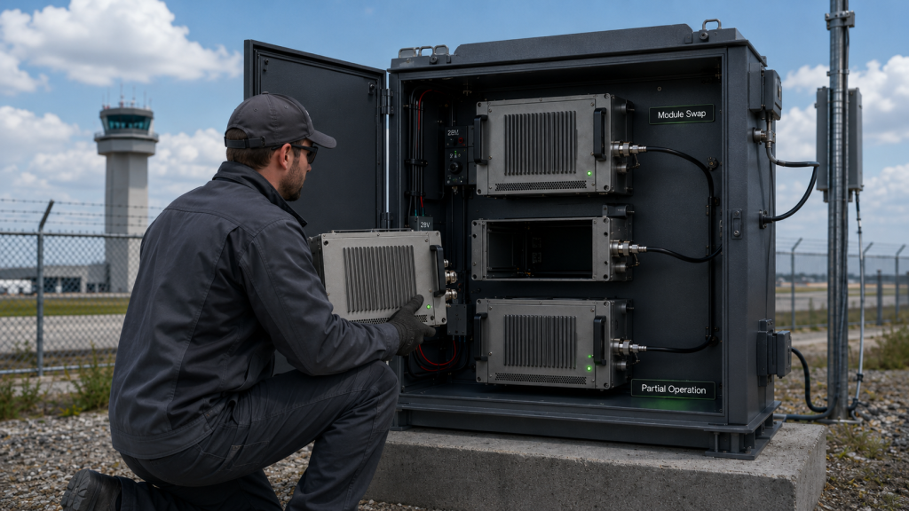
Maintenance windows can change the RF Power Amplifier decision because architecture affects how quickly a system can be diagnosed, isolated, and restored. A single high-power module may be simple during installation, but if it fails at a remote or restricted site, the whole RF path may remain unavailable until service is completed. Redundancy can reduce that pressure by allowing partial operation while one module is inspected or replaced.
Here’s the real procurement issue: initial module cost is only one part of the decision. Downtime cost, access approval, technician travel, safety procedures, cabinet opening time, spare strategy, and operator coordination can matter more than the price difference between architectures.
What Maintenance Risks Should Be Priced?
Maintenance planning should be discussed before procurement approval. The goal is to understand how the system behaves when one part needs service.
- The site is remote or difficult to access.
- Maintenance visits require approval or escort.
- The system cannot be stopped during normal operation.
- One module can be replaced faster than one large assembly.
- Fault logs can identify the affected channel.
- Spare modules can be standardized.
- The next service window may be days or weeks away.
A single 300W module may look simpler on paper. Three 100W modules may look more complex. But if one 100W module can be isolated while the system keeps partial capability, the operational value may be higher.
Key Takeaway: This section helps buyers compare initial module cost against the operational cost of downtime and service complexity.
| Maintenance Factor | One Larger Module | Redundant Modules |
|---|---|---|
| Initial wiring | Simpler | More complex |
| Fault impact | More concentrated | More isolated |
| Replacement size | Larger assembly | Smaller module path |
| Downtime risk | Higher | Lower if designed well |
| Spare strategy | Fewer part types | More modular |
| Service flexibility | Lower | Higher |
If the cost of one full stop is high, redundancy may be a maintenance strategy rather than a luxury feature.
7. How Do Heat and 28V Supply Change in Redundant Systems?
Heat and 28V supply change in redundant RF Power Amplifier systems because the design moves from one concentrated high-power load to multiple distributed module loads. A single larger module concentrates heat, current, heatsink demand, and failure impact in one location. Multiple modules can distribute some of that stress, but they also increase total system wiring, branch protection, control points, and cabinet layout requirements.
This is where redundancy must be engineered, not assumed. Multiple modules do not automatically make the system cooler. If all modules run at high duty cycle in a tight cabinet, total heat can still become severe. But a redundant architecture can allow staged operation, lower per-module load, standby capacity, or better thermal isolation when designed correctly.

What Thermal and DC Checks Matter?
The system should review total stress, not only one module’s rating. Redundancy changes where stress appears, but it does not remove the need for careful electrical and thermal design.
- Total DC current, not only per-module current.
- Module-side voltage under full load.
- Branch wiring and connector rating.
- Heat stacking between adjacent modules.
- Cabinet airflow and heatsink orientation.
- Standby and active module states.
- Failover load after one module drops out.
For high-current systems, 28V RF Power Amplifier supply margin becomes part of the redundancy decision. A backup module is not useful if the DC architecture cannot support the operating state after failover.
Key Takeaway: This section helps you avoid assuming redundancy automatically reduces heat or supply stress. It works only when thermal layout, DC distribution, and operating states are designed together.
| Design Factor | One Larger Module | Redundant Architecture |
|---|---|---|
| Heat location | Concentrated | Distributed |
| Current path | One main path | Multiple branches |
| Cabinet layout | Simpler | More complex |
| Backup behavior | Limited | Can be planned |
| Thermal isolation | Harder | More flexible |
| DC protection | Simpler | Needs branch logic |
Redundancy shifts stress. It does not delete stress. The system must distribute, monitor, and manage that stress.
8. How Do Bands, Channels, and Sectors Shape Redundancy?
Bands, channels, and sectors shape RF Power Amplifier redundancy because losing one module may mean losing one narrowband function, one wideband block, one direction of coverage, or one critical mission path. Redundancy should follow mission importance, not just module count. A system with five modules does not automatically have useful redundancy if all five are exposed to the same failure mode.
Here’s the engineering point: redundancy can be designed at different levels. It may be module-level, band-level, channel-level, sector-level, power-supply-level, or whole-system-level. The correct level depends on what the mission cannot afford to lose.

What Redundancy Level Fits the Mission?
Frequency and channel planning should connect RF design with operational priority. Not every path needs the same redundancy level.
- Which frequency bands are mission-critical?
- Which bands can be temporarily unavailable?
- Does one wideband module cover too much risk in one block?
- Do narrowband paths provide better isolation?
- Which coverage sectors are most important?
- Can one standby module serve more than one path?
- Does the controller understand band or sector priority?
A wideband RF module can reduce module count and simplify integration. But if that one wideband path fails, the affected frequency range may be broad. Narrowband modular paths can isolate faults more cleanly, but they add control and cabinet complexity.
Key Takeaway: This section helps you decide whether redundancy should be module-based, band-based, channel-based, sector-based, or system-based.
| Architecture Level | What It Protects | Typical Use |
|---|---|---|
| Module-level redundancy | One RF module path | Simple backup design |
| Band-level redundancy | Critical frequency band | Multi-band C-UAS systems |
| Channel-level redundancy | Specific RF channel | Modular RF chains |
| Sector-level redundancy | Directional coverage | Fixed-site perimeter systems |
| Supply-level redundancy | Shared DC risk | High-availability cabinets |
| System-level redundancy | Whole equipment node | Mission-critical fixed sites |
Frequency structure determines what the system really loses when one RF Power Amplifier module becomes unavailable.
9. What RF Power Amplifier Buyers Should Define
Buyers should define mission continuity, acceptable degradation, maintenance window, channel priority, duty cycle, thermal condition, supply margin, and protection feedback before asking for RF Power Amplifier redundancy. A supplier cannot responsibly answer whether one 300W module or three 100W modules is better without knowing what the system must survive.
This is where a strong RFQ makes a better architecture possible. “We need redundancy” is not enough. “We need the system to keep partial capability if one module alarms, and the site can only be serviced once every two weeks” is much more useful.

What Should the RFQ Include?
The RFQ should describe mission behavior after a local problem, not only rated output power. That lets engineering teams compare higher-power and redundant approaches fairly.
- Is full downtime acceptable?
- What level of degraded operation is acceptable?
- Which bands or directions have priority?
- How long is the maintenance window?
- Is the site remote, restricted, or easy to access?
- What is the expected duty cycle?
- What is the highest ambient and cabinet temperature?
- What protection signals must be reported?
- Is the spare strategy module-based or system-based?
The supplier also needs to know whether the target power is measured at the module output or after cable loss at the antenna side. If that point is unclear, the discussion may confuse power sizing with redundancy planning.
Key Takeaway: This section helps buyers ask for an architecture recommendation instead of only requesting a higher wattage quote.
| RFQ Information | Why It Matters |
|---|---|
| Downtime tolerance | Determines redundancy need |
| Degraded mode | Defines acceptable reduced operation |
| Band priority | Guides backup placement |
| Duty cycle | Affects thermal and supply load |
| Site access | Affects maintenance strategy |
| Protection feedback | Enables controlled failover |
| Output reference point | Separates power sizing from redundancy |
A better RFQ does not only ask for a module. It asks for system behavior after one part becomes unavailable.
10. How Should You Choose Higher Power or Redundancy?
You should choose higher power when the main RF Power Amplifier problem is output capacity, and choose redundancy when the main system problem is mission continuity, maintenance tolerance, or single-point failure risk. The decision should come after reviewing target output, power margin, thermal condition, 28V supply, duty cycle, frequency priority, protection feedback, and acceptable degraded mode.
Here’s the final decision logic. If the antenna-end power is too low because of feeder loss, start with power margin and RF path review. If the module overheats under long duty cycle, review thermal path and operating profile. If one module fault stops the whole mission, evaluate redundancy. If the control system cannot support failover, do not pretend that extra modules alone create redundancy.

What Final Checklist Should You Use?
A practical decision checklist should connect power, risk, service, and system behavior. It should not treat redundancy as a premium label or higher power as a universal shortcut.
- Need stronger single-path output? Consider higher power.
- Need to survive one module alarm? Consider redundancy.
- Need to protect a critical band? Consider band-level redundancy.
- Need to protect a critical direction? Consider sector-level redundancy.
- Need shorter service downtime? Consider modular replacement.
- Need the simplest system? Keep architecture simpler.
- Cannot define degraded mode? Redundancy is not ready.
- Cannot read module alarms? Failover logic is not ready.
- Cannot support added DC load? Redundancy may create new risk.
The useful question is not only “How many watts do you need?” It is also “What must the system still do when one RF path is not available?”
Key Takeaway: This section helps you make the final architecture choice based on mission risk, not only module wattage.
| Main Risk | Better Architecture Discussion |
|---|---|
| Single-path output is too low | Higher-power module |
| Field loss consumes output | Power margin and RF path review |
| High duty cycle creates heat stress | Thermal and duty-cycle review |
| One module fault stops mission | Redundancy design |
| Site access is difficult | Modular maintenance strategy |
| Critical band cannot be lost | Band-level redundancy |
| Control cannot support failover | Simpler design or control redesign |
The strongest architecture is not always the one with the largest module. It is the one that keeps the mission aligned with power, heat, control, maintenance, and risk.
FAQ
Can I use one larger RF Power Amplifier instead of redundancy?
Yes, if the main requirement is stronger single-path output and downtime is acceptable. A larger module can be the right choice for simpler platforms, short-duty operation, or systems with fast maintenance access.
What’s the best redundancy design for C-UAS systems?
The best redundancy design depends on mission priority, frequency bands, coverage sectors, maintenance access, and acceptable degraded operation. Some systems need module-level redundancy, while others need band-level or sector-level redundancy.
How do I know if redundancy is worth the cost?
Redundancy is worth reviewing when the cost of downtime is higher than the added cost of extra modules, control logic, cabinet space, and maintenance planning. If one module fault creates unacceptable mission loss, redundancy may be justified.
Can protection logic replace redundancy?
No. Protection logic helps identify and manage faults, while redundancy allows the system to continue operating after a local problem. A good system usually needs both.
What should I tell the supplier before choosing redundancy?
Tell the supplier your downtime tolerance, maintenance window, critical bands, duty cycle, cabinet conditions, supply margin, protection feedback needs, and acceptable degraded mode. Without that context, the supplier cannot fairly compare higher power and redundancy.
Conclusion
RF Power Amplifier redundancy is not a bigger version of power sizing. It is a system availability decision. A higher-power module may solve weak single-path output, but it does not remove single-point failure risk. Redundancy becomes important when one module alarm, derating event, service action, or failure cannot be allowed to stop the whole C-UAS mission.
This article compared one larger module with multiple redundant modules across output capacity, mission continuity, maintenance windows, thermal and 28V supply pressure, frequency priority, protection feedback, RFQ information, and final architecture selection. The strongest answer depends on the mission: sometimes one higher-power module is cleaner; sometimes a redundant architecture is the safer operating strategy.
RF SKYPOWER can help system integrators review whether a project should use higher single-module output or a redundant RF module architecture. We can support early discussion around power target, frequency band, duty cycle, thermal condition, supply margin, protection feedback, cabinet layout, test evidence, and acceptable degraded mode. To review your RF architecture before the final design is locked, contact us today.
Reliable C-UAS RF architecture is not built by chasing the largest wattage number; it is built by matching output power, module protection, maintenance strategy, and mission continuity to the same engineering standard.