











Common drone bands are a useful starting point for RF PA selection, but they can become an upgrade trap when a long-term C-UAS cabinet is designed only for today’s known links. A later frequency requirement may need another PA path, RF switch port, antenna route, DC branch, cooling reserve, control channel, and acceptance test—not just a software setting.
Before choosing custom RF Power Amplifier modules, the integrator should separate day-one bands from possible future requirements. The project should then decide how much physical, electrical, thermal, RF, and control reserve is worth purchasing before the first cabinet is built.
A low-cost common-band cabinet can become the most expensive option when one later frequency requirement forces a new power supply, cooling layout, RF switch, antenna route, controller, and acceptance program.
This article focuses on RF PA expansion readiness. A later approved band should not require a complete cabinet and RF-chain rebuild.
1. What Common Drone Bands Can—and Cannot—Prove
A common-band list proves that the project has identified its current must-cover frequencies. It does not prove that the installed system can accept another RF path later.
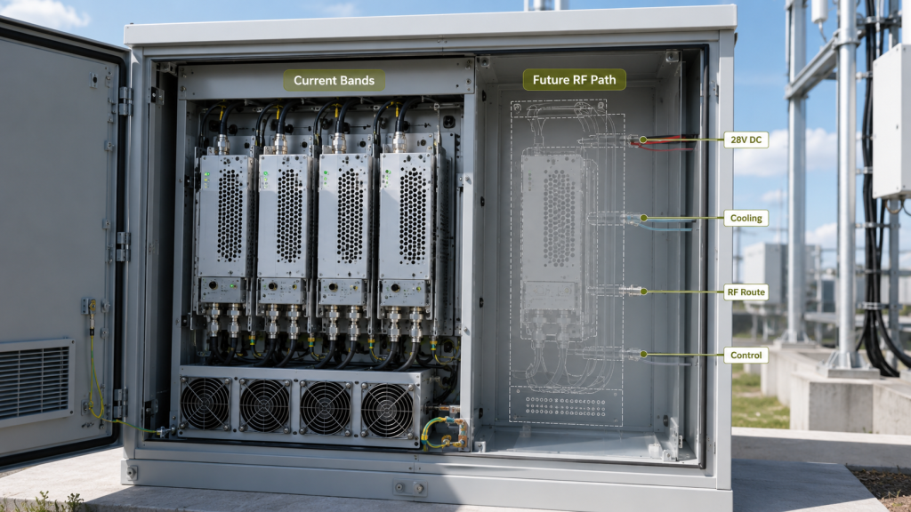
Two systems may begin with the same frequency list but require different engineering decisions.
A short-term deployment with a fixed operating scope may prioritize current coverage, lower cost, and simpler integration. A permanent airport, border, critical-infrastructure, or fixed-site installation may need to remain usable through several equipment and threat cycles.
For a long-term system, three questions matter:
- Can another RF path be installed?
- Can the cabinet power and cool it?
- Can the added path be controlled, protected, and accepted?
A current frequency list does not answer these questions.
The day-one frequency requirement should first be defined through a proper RF PA frequency range selection process. Expansion planning begins after the present operating boundary is clear.
Covering current bands proves present compatibility. It does not prove future expansion readiness.
2. When Is a Fixed Common-Band RF PA Plan Enough?
Not every project needs spare module positions, unused power branches, or broad future-frequency coverage.
A fixed common-band design may be appropriate when:
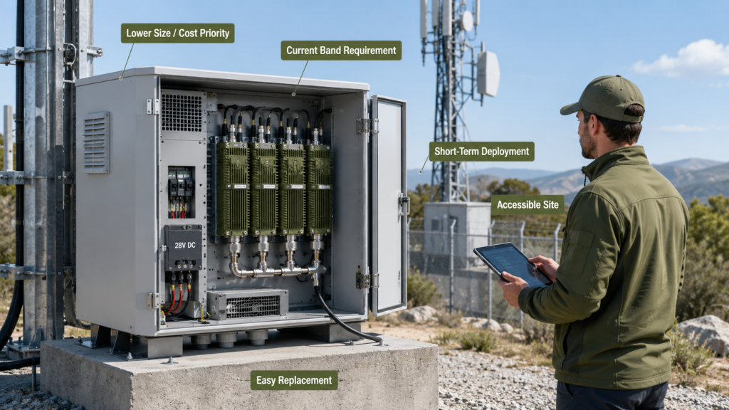
- The deployment period is short.
- The operating scope is contractually fixed.
- The site is easy to access.
- Cabinet replacement is acceptable.
- Additional frequency paths are unlikely.
- Future changes can be treated as a new system build.
- Lower size, weight, cost, and complexity are higher priorities.
In these cases, reserving excessive cabinet space, current capacity, cooling, and unused RF hardware may add cost without creating practical value.
However, the decision must be deliberate.
The RFQ should clarify whether the listed frequencies represent:
- The complete expected deployment life
- Only the first procurement phase
- A temporary regional requirement
- The current threat list
- A limited acceptance scope rather than the final system scope
A fixed design is reasonable when later replacement is acceptable. It becomes risky when the customer expects a long service life but the cabinet is sized only for the first frequency list.
3. Which Future Changes Create an RF PA Upgrade Risk?
Expansion planning becomes important when the operating environment, site layout, or acceptance scope may change after installation.
Typical triggers include:
- A long expected deployment life
- A remote or difficult-to-modify site
- Changing regional frequency use
- New approved links or protocols
- Additional sectors or antenna zones
- A requirement for field-installable modules
- Higher output in an existing band
- A future split between separate controlled RF paths
- New control, alarm, or reporting requirements
- New acceptance evidence for every added path
The most common mistake is assuming that a software-defined signal source makes the complete RF chain software-expandable.
It does not.
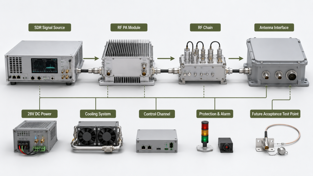
A new waveform or center frequency may be configured in software, but the PA, filter, switch, feeder, antenna, power supply, cooling system, controller, and test plan must also support the added band.
Large or complex deployments may require a dedicated C-UAS frequency strategy for protected bands, site zones, sectors, and antenna placement. This article addresses a narrower issue: whether the PA cabinet can physically and electrically support an approved future expansion.
4. What Expansion Reserve Must Be Designed Before Purchase?
Expansion readiness should be defined through measurable engineering limits.
Those limits should be converted into an RF PA upgrade-margin budget that compares verified capacity, phase-one use, phase-two requirement, remaining margin, and Pass/Fail evidence for every resource.
Statements such as “future-proof,” “easy to upgrade,” or “supports additional bands” are not sufficient for procurement or acceptance. The RFQ should state what reserve will exist after the day-one configuration is installed.
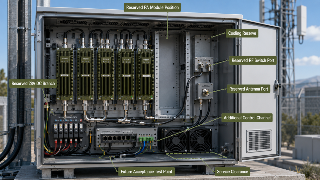
Common-Band Plan vs Expansion-Ready RF PA Design
| Design Area | Current-Band-Only Design | Expansion-Ready Design | Evidence to Request |
|---|---|---|---|
| Cabinet | Sized only for installed modules | Reserved module position and service space | Mechanical layout |
| 28V DC | Sized for current load | Defined additional current and isolated branch | Voltage and current budget |
| Cooling | Based on present heat load | Future PA heat load included | Thermal calculation or hot-state test |
| RF path | No spare route or output | Spare switch port, connector, or feeder provision | RF block diagram |
| Antenna interface | Current antennas only | Additional port or antenna path reserved | Interface drawing |
| Control | Fixed number of channels | Spare command, status, and alarm capacity | Control-interface map |
| Acceptance | Current paths only | Future test boundary predefined | Report template |
RF PA Expansion Reserve Checklist
Before approval, define:
- Reserved PA module position
- Spare RF or antenna port
- Maximum additional 28V DC current
- Isolated spare DC branch
- Remaining cooling capacity
- Available feeder route
- Filter and RF switch compatibility
- Additional signal-source or control channel
- Protection and alarm mapping capacity
- Test points for future acceptance
- Space for module identification and S/N traceability
Cabinet reserve
Reserved cabinet space must include mounting, connector access, grounding, airflow, cable routing, and service clearance—not only empty volume.
A nominally open position is not useful if a future PA blocks airflow, cannot connect to the DC bus, or requires new cabinet machining.
28V DC reserve
The supplier should state the additional current available at the PA input under load.
That value must account for power-supply capacity, cable voltage drop, connectors, branch protection, startup behavior, and simultaneous operation. A spare fuse position does not prove that the supply and wiring can support another module.
Thermal reserve
Future heat load should be included before module spacing and airflow are locked.
If the cabinet already operates close to its temperature limit, an empty module position does not provide a usable expansion path. The thermal review should show that the added PA can operate at its required output without forcing existing paths into temperature protection or output foldback.
5. Which RF PA Architecture Reduces Future Upgrade Cost?
Different PA architectures create different expansion advantages and risks.
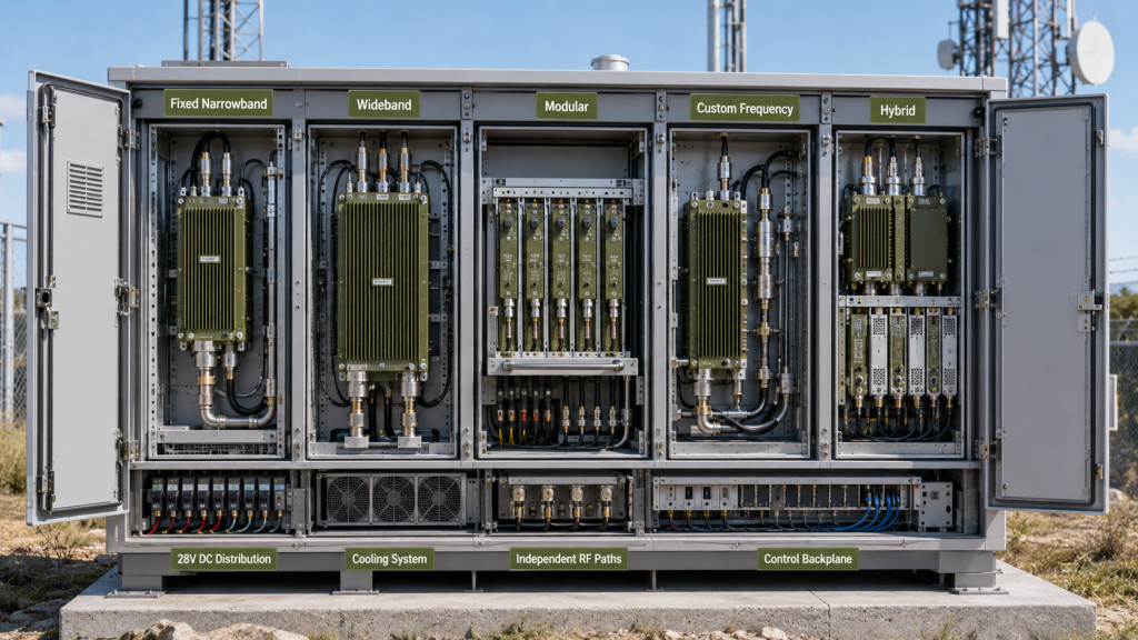
| Architecture | Future-Band Advantage | Main Upgrade Risk |
|---|---|---|
| Fixed narrowband | Strong performance within known bands | A new band often requires another complete RF path |
| Wideband | May cover a larger planned frequency window | Catalog coverage does not prove required output across the range |
| Modular | Additional paths may be installed independently | Space, DC, cooling, RF routing, and control reserve must already exist |
| Custom frequency | Can match a defined lifecycle requirement | Requires confirmed frequency, output, and system boundaries |
| Hybrid | Combines fixed high-priority paths with expandable capacity | More integration and acceptance complexity |
Fixed narrowband
A fixed narrowband architecture may provide good efficiency and predictable performance when the frequency plan is stable.
Its lifecycle risk is that a later band may require another PA, filter, switch route, antenna interface, power branch, and acceptance test.
Wideband
A wideband PA may reduce the need for multiple individual modules, but catalog frequency coverage alone does not prove expansion readiness.
The RFQ must still define:
- Required output across the planned range
- Gain flatness
- Hot-state behavior
- Input drive
- Filtering
- Antenna compatibility
- Protection response
- Test reference plane
The supplier should provide verified wideband RF PA performance at the relevant frequencies and operating conditions.
Modular
A modular design may offer the clearest field-upgrade path, provided the interfaces were reserved before purchase.
The cabinet must already support the future module mechanically, electrically, thermally, and through the control system. Calling a product modular does not prove that another RF path can be installed without redesign.
Custom frequency
A custom RF PA frequency range may be appropriate when standard narrowband or wideband options do not match the required combination of coverage, output, efficiency, cabinet size, and lifecycle plan.
Custom coverage should be based on confirmed engineering requirements, not a vague request for the widest possible range.
The best architecture is not always the one with the broadest catalog specification. It is the one that satisfies the current requirement and preserves the approved upgrade path with measurable performance.
This decision remains part of the wider C-UAS RF PA selection workflow, rather than becoming a frequency-only choice.
6. What Should the RFQ and Acceptance Plan Preserve?
The RFQ should separate day-one requirements from future expansion assumptions.
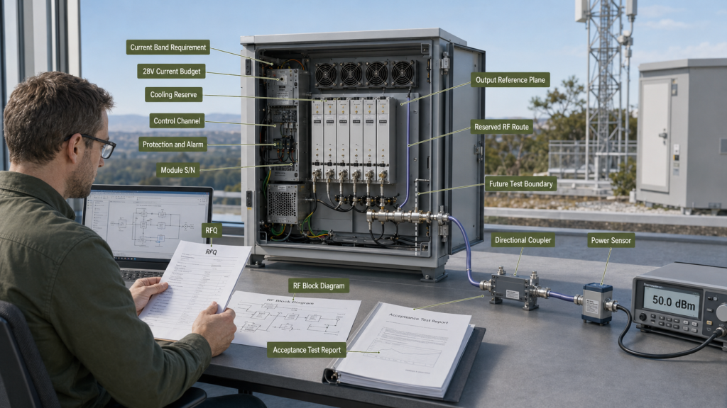
Day-one requirements
Define:
- Current must-cover bands
- Output target by band
- PA-port or antenna-end reference plane
- Duty cycle
- 28V supply boundary
- Cooling method
- Control interface
- Protection requirements
- Required acceptance evidence
Future expansion assumptions
Define:
- Likely future frequency window
- Expected deployment life
- Number of possible additional RF paths
- Maximum acceptable cabinet modification
- Whether field installation is required
- Reserved antenna and RF routing
- Additional 28V current
- Cooling reserve
- Additional control-channel capacity
- Test evidence required after the upgrade
Avoid phrases such as:
- Future-proof design
- Wideband flexibility
- Easy expansion
- Additional bands later
- Modular upgrade
These statements cannot be tested.
Use a measurable requirement instead:
The cabinet shall reserve one PA module position, one isolated 28V DC branch, one RF output route, sufficient cooling capacity, and one additional control channel for a future approved frequency path.
The initial acceptance package should show:
- Installed RF paths
- Reserved module location
- 28V current budget
- Spare DC branch
- Cooling reserve
- RF routing provision
- Available control channel
- Alarm and protection capacity
- Future output reference plane
- Cabinet and module identification
When the new path is installed, its acceptance test should verify output, voltage, current, temperature, forward and reflected power, VSWR, control status, alarm behavior, interaction with existing paths, and updated S/N-linked evidence.
A block diagram may show an intended expansion path. Physical inspection and test evidence must prove that the reserve actually exists.
Conclusion
Common drone bands are a useful starting point, but they should not define the complete lifecycle of a long-term C-UAS RF system.
A fixed common-band design may be appropriate for a short, stable deployment. It becomes a procurement risk when the customer expects future expansion but the cabinet has no reserved PA position, 28V capacity, cooling margin, RF route, antenna port, control channel, or acceptance boundary.
The project does not need to predict every future frequency. It needs to define how much expansion reserve is worth purchasing now.
RF SKYPOWER can support early engineering review for expansion-ready RF PA architectures. Send the current must-cover bands, possible future frequency window, power target by band, PA-port or antenna-end reference, expected deployment life, cabinet-space reserve, antenna-port reserve, 28V DC margin, cooling method, control-channel capacity, protection feedback, and required S/N-linked test evidence.
Contact RF SKYPOWER before the cabinet, DC distribution, antenna routing, and control architecture are locked.