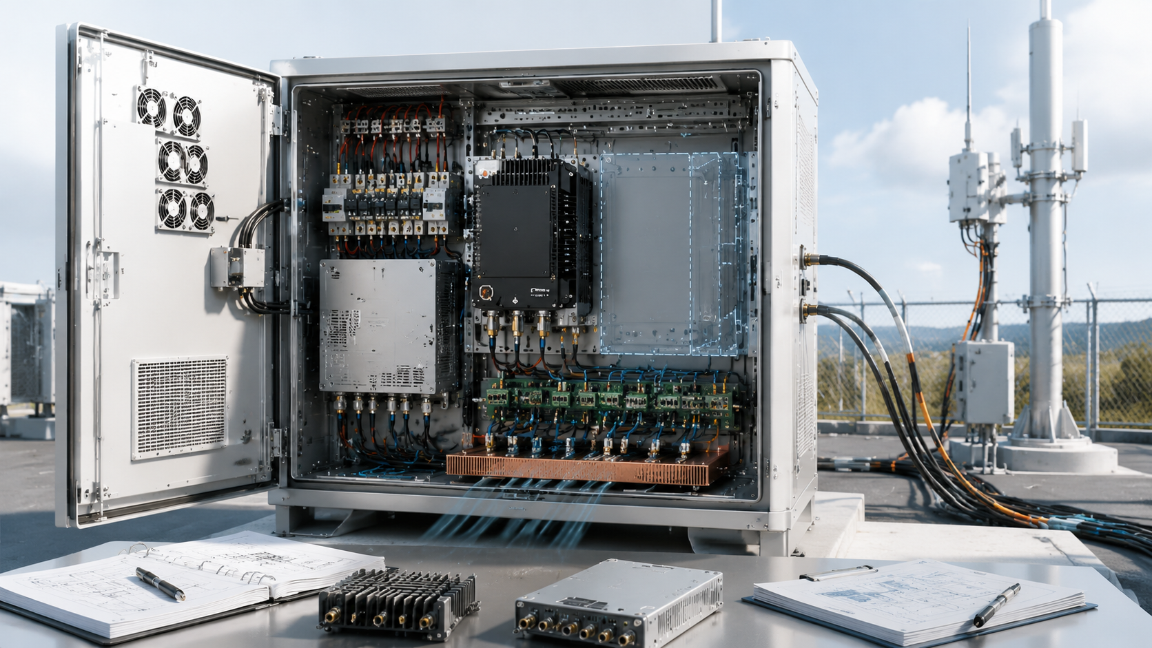
How to Calculate RF PA Upgrade Margin Before Cabinet Design
June 9, 2026
RF PA upgrade margin is the verified capacity that remains after the phase-one cabinet, 28V DC system, cooling path, RF routing, control channels, and test boundaries have been defined.
An empty cabinet position does not prove that another module can be installed. The DC supply may already be near its continuous-current limit. The cooling path may be fully loaded. The RF switch may have no qualified spare port. The controller may have no independent address or alarm capacity for another PA module.
Before choosing custom RF Power Amplifier modules, calculate each phase-two requirement against the verified capacity left after phase one.
The upgrade passes only when every required resource has a documented positive margin under the same approved operating boundary.
1. What RF PA Upgrade Margin Actually Measures
Several types of margin may appear in one RF PA project, but they answer different questions.
Term
What It Measures
RF power margin
Output headroom in the current RF path at a defined reference plane
28V voltage margin
Loaded module-input voltage above the approved performance boundary
Upgrade margin
System resources reserved for a defined future configuration
Redundancy
Capability that remains available after a fault
RF PA power margin determines whether the current RF path still meets its required output after path loss, band-edge variation, thermal conditions, and project reserve are considered.
28V RF PA voltage margin determines whether the module receives enough voltage under load to maintain approved performance.
Upgrade margin answers a different question:
Can the system accept a defined future PA module or RF path without rebuilding the cabinet, DC distribution, cooling, RF routing, and control architecture?
Redundancy also has a separate role. It defines what remains operational after a module or path fails. A system may have redundancy for its current configuration but no capacity for future expansion. It may also have excellent upgrade capacity but no fault tolerance.
These terms should remain separate in the RFQ and test report.
2. What Phase-Two Load Must Be Defined Before Margin Is Calculated?
Upgrade margin cannot be calculated from a vague request such as “support another band later.”
Phase two should define:
Frequency range
Required RF output
Output reference plane
Duty cycle
Module count
Expected 28V current
Heat load
RF switch and filter path
Feeder and antenna connection
Control and alarm channels
Protection behavior
Acceptance evidence
A measurable phase-two requirement might state:
Phase two shall add one independently controlled RF PA path for the approved frequency range, with output verified at the cabinet RF connector under the specified duty cycle and hot-state condition.
This gives the supplier a real electrical, thermal, mechanical, and RF load to review.
Statements such as these are not sufficient:
Future expansion
Another module
Additional capacity
Wider frequency support
Modular upgrade
Spare output
They do not define how much current, cooling, cabinet space, RF routing, or control capacity must remain available.
A lean phase-one design may still be reasonable when the future configuration is unlikely, the site is easy to modify, or cabinet replacement is acceptable. However, the system should not be described as expansion-ready unless the phase-two resource budget has been calculated.
The lifecycle risk behind this decision is covered in RF PA expansion beyond common drone bands. The next step is to prove whether the required capacity actually remains.
3. How to Calculate Cabinet, DC, Thermal, RF, and Control Margin
The core calculation is:
Available upgrade margin = Verified capacity − Phase-one worst-case use
The phase-two configuration passes when:
Available upgrade margin ≥ Phase-two requirement + approved project reserve
Each resource must be calculated in its own unit. Cabinet positions, amperes, thermal limits, RF ports, control channels, and acceptance boundaries cannot be combined into one percentage.
RF PA Upgrade-Margin Budget
Resource
Verified Capacity
Phase-One Use
Phase-Two Requirement
Remaining Margin
Pass/Fail
Evidence
Cabinet
Define
Define
Define
Calculate
Pass/Fail
Mechanical drawing
28V DC
Define
Define
Define
Calculate
Pass/Fail
Loaded voltage/current test
Thermal
Define
Define
Define
Calculate
Pass/Fail
Hot-state thermal evidence
RF path
Define
Define
Define
Calculate
Pass/Fail
RF block diagram
Control
Define
Define
Define
Calculate
Pass/Fail
Interface map
Acceptance
Define
Define
Define
Calculate
Pass/Fail
Test-plan template
Cabinet margin
Available cabinet margin = Qualified usable positions − Phase-one positions
A position counts only when mounting, connector access, grounding, airflow, cable routing, and service clearance are already defined.
Empty volume does not count when the future module would block airflow, require cabinet machining, or prevent access to adjacent connections.
28V DC margin
Available DC current margin = Verified continuous supply-path capacity − Phase-one worst-case current
The remaining capacity must support the phase-two continuous load, startup behavior, and approved reserve while maintaining the required voltage at the module input.
The calculation should include:
Power supply
Distribution wiring
Connectors
Fuse or breaker
Switching devices
Return path
Voltage drop under load
A spare fuse position does not prove that the complete 28V path can support another PA.
Thermal margin
Thermal margin must use the same verified thermal metric for both capacity and use. Depending on the design, that metric may be:
A spare connector counts only when the related switch port, filter, feeder route, connector rating, antenna interface, insertion loss, and output reference plane are defined.
Where feeder loss affects the final requirement, use the same reference-plane discipline applied in RF PA feeder cable loss verification.
Control margin
Available control margin = Independent channels available − Phase-two channels required
The future PA path should have defined support for:
Independent enable and disable
Frequency or path selection
Power-state control
Temperature status
Forward and reflected-power status
Fault identification
Protection state
Reset and recovery
Event logging
A shared cabinet alarm does not prove that another module can be independently operated, diagnosed, and accepted.
4. Which Resource Becomes the Upgrade Bottleneck?
Some spare capacity is not an approval criterion. Every phase-two resource must pass its own margin check.
For example, a cabinet may have:
One spare PA position
18A of remaining DC capacity
Sufficient cooling
Two unused control addresses
No qualified RF switch port
The upgrade fails because the RF path margin is zero.
Upgrade Bottleneck: A future configuration is not approved when any required cabinet, DC, thermal, RF, control, or test resource has negative or undefined remaining margin.
One missing RF port can invalidate available cabinet, DC, thermal, and control capacity. The project then requires RF-chain redesign rather than a simple module addition.
Depending on the failed resource, the redesign may require:
A larger cabinet
A new DC supply
Revised cooling
Another RF switch
A new filter assembly
Additional feeder routing
Controller replacement
New protection logic
Repeated acceptance testing
The first failed resource defines the redesign scope.
5. Which Upgrade Architecture Fits the Margin Result?
The upgrade architecture should follow the calculated resource limits, not a general preference for modular or wideband hardware.
Upgrade Path
Use When
Main Risk
Add-on PA module
Every required resource margin passes
All interfaces must already be qualified
Wider-band replacement
No spare slot exists, but one current path can be replaced
Full-range output may not meet the requirement
Shared-path modification
Existing switch, feeder, or antenna route can be reused
Added loss and shared failure points
Separate expansion enclosure
The current cabinet fails one or more resource checks
More external DC, control, cooling, and environmental work
Add-on module
An add-on PA path is practical when the cabinet position, 28V capacity, cooling, RF route, control channel, and acceptance boundary all pass.
It provides a clear expansion path without replacing the phase-one modules.
Wider-band replacement
Replacing an existing PA with a wider-band module may avoid adding another physical slot.
However, the replacement must still meet:
Output across the required range
Gain-flatness limits
Hot-state performance
Input-drive conditions
Filter and antenna compatibility
Control requirements
Protection behavior
A wider catalog frequency range does not prove usable output across the full operating range.
Shared-path modification
Reusing an existing RF switch, feeder, filter, or antenna path may reduce cabinet changes, but it can introduce:
Additional insertion loss
Switching dependencies
Shared failure points
New reflected-power behavior
More complex control logic
The modified path must be accepted as a complete RF chain.
Separate expansion enclosure
A separate enclosure may be more practical when the phase-one cabinet lacks one critical resource.
It avoids rebuilding the original cabinet but may require new DC distribution, cooling, RF routing, control networking, environmental protection, and acceptance documentation.
6. What Evidence Must Be Locked Before RFQ Approval?
Upgrade margin should be supported by consistent design, capacity, and acceptance evidence.
Design evidence
Phase-one and phase-two configurations
Mechanical layout
Reserved module position
DC distribution diagram
RF block diagram
Feeder and antenna routing
Control-interface map
Protection and alarm mapping
Capacity evidence
Verified continuous 28V capacity
Phase-one worst-case voltage and current
Phase-two current requirement
Hot-state thermal result
Available RF ports and routes
Available control addresses and status channels
Acceptance evidence
Future output reference plane
Required test frequencies
Duty cycle
Forward and reflected-power method
VSWR boundary
Temperature boundary
Report format
S/N traceability requirement
Pass/Fail result for every resource
The buyer should provide the phase-one and phase-two frequency ranges, module counts, output targets, duty cycles, cabinet limits, 28V boundary, cooling method, RF routing, antenna-port requirement, control map, protection behavior, and test-report requirements.
All drawings and calculations should describe the same cabinet revision.
A mechanical drawing may show a spare PA position while the current budget and thermal evidence cover only the installed modules. That mismatch does not prove upgrade capacity.
The acceptance package should clearly state:
What capacity was verified
Which operating boundary was used
What phase one consumes
What phase two requires
What margin remains
Which resource becomes the bottleneck
Whether the complete upgrade path passes
Conclusion
RF PA upgrade margin is not spare cabinet space, unused power-supply wattage, or a claim that the system is modular.
It is the verified remaining capacity across every resource required by a defined phase-two configuration.
A future upgrade fails when one required resource is missing. A spare PA slot cannot compensate for insufficient 28V current, cooling, RF routing, control capacity, or acceptance evidence.
RF SKYPOWER can support early engineering review for staged RF PA deployments. Send the phase-one and phase-two frequency ranges, module counts, output targets, duty cycles, cabinet limits, available 28V capacity, cooling boundary, RF switch and feeder plan, antenna-port requirement, control-channel map, protection logic, and required S/N-linked test evidence.
Contact RF SKYPOWER before one missing slot, DC branch, heat path, RF port, or control channel turns phase-two expansion into a full cabinet rebuild.
Contents
About Our Company
RF SKYPOWER is a Source Factory engineering precision RF modules, antennas, SDR signal sources, and detection systems built exclusively for defense, security, and critical infrastructure applications.
When R&D, manufacturing, and testing happen under one roof, you get unmatched quality control and supply chain stability.