










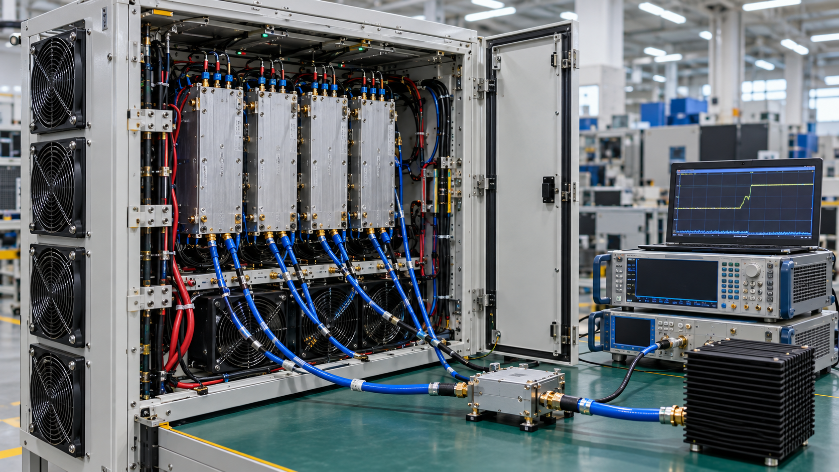
When every RF PA passes alone but a multi PA cabinet fault appears only with several modules active, start by treating the problem as a shared-system interaction rather than proof that one amplifier is defective. That working assumption is valid only when the single-module and combination tests are reasonably comparable in frequency, Actual Pin, Pout, waveform or duty, RF load, supply boundary, cooling state, and measurement reference planes, with the active combination and event timing recorded.
The same visible symptoms, including output drop, Alarm, reset, or communication instability, can begin in DC distribution, thermal conditions, RF/EMI/ground interaction, or control timing. First find the smallest combination that reproduces the fault. Then identify which measurable boundary changes first. That first change tells you where to investigate next. It is not yet the root cause.
1. Why Can Every PA Pass Alone but the Cabinet Still Fail?
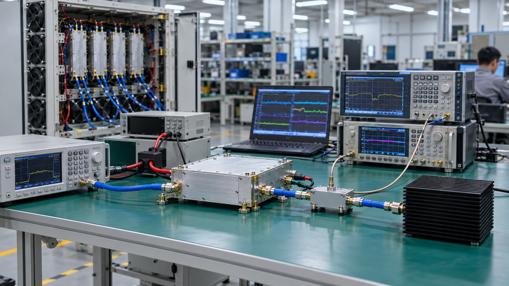
A single-module PASS verifies one PA under the conditions applied during that test. It does not exercise the shared conditions that appear when several channels operate together.
Multi-module operation can change shared DC and return current, heatsink and airflow loading, RF coupling, ground-reference behavior, simultaneous control activity, RF switching states, and interactions among protection functions.
For troubleshooting, a combination operating state is the defined set of active channels together with their frequency, drive, output, load, cooling, supply, control state, and timing. An approved all-on state, or the maximum approved simultaneous combination when the system does not permit every PA to transmit at once, is a separate engineering state from a series of isolated single-channel tests.
The first PA to report an Alarm is therefore only the first visible symptom. Another change elsewhere in the cabinet may have pushed that module across a protection or control threshold. The investigation may eventually lead back to a specific module, slot, branch, RF route, protection setting, or control state, but the Alarm alone cannot make that distinction.
Before assigning the fault to simultaneous operation, align the important per-channel conditions. Material differences in frequency, Pout, RF load, cooling, or measurement conditions make the single and combination results only partially comparable.
After resolving an all channel RF amplifier fault, check channel-to-channel output behavior separately under the multi-band RF power consistency framework.
2. How Do You Create a Valid Single-vs-All-Channel Baseline?
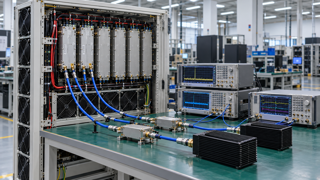
The active combination should be the main controlled change.
For each active channel, record the module identity and S/N, slot or channel, frequency, waveform or duty, Actual Pin at the defined PA input reference plane, Pout at the defined output reference plane, RF load or antenna path, PA-terminal Vdc, per-PA Idc, thermal state, protection state, control configuration, and test duration.
Actual Pin is the power available at the defined PA input reference plane after the applicable source-path correction. The signal-generator setting alone does not establish Actual Pin.
Some quantities will change naturally as more modules are enabled. Total cabinet current, distribution loading, airflow temperature, heatsink temperature, and other shared conditions may rise because the operating combination has changed. Record those changes with enough timing information to determine whether they precede the fault, follow it, or only occur alongside it.
Cabinet configuration belongs in the same baseline. Record whether the enclosure is open or closed, cooling mode and fan state, the relevant thermal starting condition, and any RF routing or switching state that changes between tests.
Without that information, a reported “single-channel pass, all-channel fail” may also contain changes in cooling, RF path, or control conditions.
If several RF, DC, thermal, or control conditions change at once and cannot be traced, stop the root-cause decision and rebuild the baseline. Cross-domain fault isolation requires a usable comparison before it requires an explanation.
3. Which Channel Combination First Reproduces the Fault?
For multi channel RF amplifier troubleshooting, jumping from individual-module tests straight to an all-on test gives little isolation value. Find the minimum repeatable fault combination: the smallest architecture-relevant set of simultaneously active channels that reproduces the same fault under comparable conditions.
Choose combinations from the cabinet architecture rather than testing every mathematical permutation.
Start with each module individually. Then test pairs or small groups that share a DC branch, thermal zone, control path, RF switching path, or likely frequency interaction. Include the project-approved maximum simultaneous combination as a defined system state, but do not use it as the only combination test.
Enable order also matters. Simultaneous and staggered enable can produce different current transitions, thermal histories, state-completion timing, and protection interactions even when the same channels are active afterward. Record both the order and timestamps.
For each run, capture the combination, the first channel that becomes abnormal, and the first measurement that departs from baseline. A one-time event is too weak for a firm domain assignment. The fault condition needs to repeat.
Use the same record format for individual modules, selected combinations, the maximum approved simultaneous state, and the corrective-action retest:
| Test state / active combination | Enable order | Affected channel | First changed measurement | DC evidence | Thermal evidence | RF / VSWR evidence | Control / Alarm evidence | Fault association | Next specialist route | Result |
|---|---|---|---|---|---|---|---|---|---|---|
| Single-module baseline | Normal sequence | None / channel ID | Baseline or none | PA-terminal Vdc / Idc | Temperature / cooling state | Pout / FWD / REV / VSWR | Ready / Alarm / protection | S/N / slot / branch | None unless abnormal | PASS / FAIL / HOLD |
| Selected pair / group | Simultaneous or staggered | First affected channel | Earliest repeatable change | Compare with baseline | Compare thermal zone | Compare RF behavior | Compare state / Alarm | Module / slot / branch / combination / order | Route by first change | Reproducible / not reproducible |
| Minimum repeatable fault combination | Reproducing order | First abnormal channel | First changed boundary | Vdc / Idc at event | Thermal state at event | Pout / FWD / REV / VSWR | Ready / Alarm / reset / timeout | Strongest repeatable association | DC / thermal / RF-EMI-ground / control | Fault reproduced / HOLD |
| Maximum approved simultaneous combination | Approved enable rule | Affected channel(s) | Compare with minimum fault combination | Supply / current evidence | Cooling / thermal state | Defined RF-path evidence | Synchronized status | Confirm association | Continue or redirect | PASS / FAIL / HOLD |
| Same-combination retest after correction | Same reproducing order | Channel or none | Original change returns or not | Repeat same DC evidence | Repeat same thermal evidence | Repeat same RF evidence | Repeat same control evidence | Confirm prior association | Close / continue / redirect | Retest result |
This matrix is a cross-domain routing record. Detailed DC, thermal, EMI, grounding, and control investigations still require their own procedures.
4. Which System Boundary Changes First: DC, Thermal, RF Coupling, or Control?

For a C-UAS simultaneous RF PA failure, the key cross-domain evidence is the first changed boundary: the earliest repeatable measurable deviation during the same fault event and operating combination, within the available time resolution.
Use a common trigger or a time base that can be reasonably correlated across instruments and controller logs. A voltage event from one run, a temperature reading from another, and an Alarm from a third cannot be assembled into one causal sequence.
If several domains change inside the available time resolution and their order cannot be separated, keep the case cross-domain and improve the synchronized evidence.
Does the DC Boundary Change First?
Watch the source and distribution behavior where available, but measure what reaches the PA.
PA-terminal Vdc and per-PA Idc around the fault trigger are especially important. A stable source display does not establish that every PA terminal remains at the same voltage during a shared current transition.
If a repeatable Vdc or current change occurs before the RF output or control failure and follows a shared branch, return path, or load transition, move next to the shared DC bus interaction investigation.
At this stage, the evidence identifies the DC domain. It does not distinguish among the power supply, cable, connector, return path, distribution hardware, or another DC element.
Does the Thermal Boundary Change First?
Compare the approved module or baseplate temperature measurement, thermal zone, neighboring PA activity, cooling state, and Pout as the fault develops.
A fault that repeatedly appears only after the same multi-module combination reaches a similar thermal state should move into the thermal investigation, especially when the behavior follows a shared thermal zone rather than a particular S/N.
The next boundary is shared heatsink thermal interaction.
Temperature rise alone is not enough to reject the heatsink or airflow design. Project-specific temperature limits, derating behavior, and acceptance boundaries still need their applicable evidence.
Does RF / EMI / Ground Interaction Appear First?
If PA-terminal DC and the relevant thermal state stay stable within the observation window, but multiple active RF channels immediately produce detector drift, false Alarm behavior, communication instability, status changes, or channel interaction, investigate RF coupling, EMI, shielding, and grounding.
When the event tracks RF-field or channel-interaction conditions, continue with RF PA shielding and EMI coupling.
When it tracks a shared reference, return, or common-mode path, continue with RF PA grounding and shared return.
These observations choose the next investigation boundary. They do not establish EMI, shielding, or grounding as the final cause on their own.
Does the Fault Follow Startup or Control Timing?
Compare simultaneous and staggered enable using the same module combination.
If staggered enable works while simultaneous enable fails, or if the result changes with Ready, timeout, retry, restart, or enable order, investigate timing next. Sending commands at the same time does not establish that every PA reached the intended operating state at the same time.
If startup or restart state transitions change before the RF symptom, verify the SDR-to-PA power-on sequence.
If command response, Ready completion, timeout, or retry behavior changes first, verify AT command timing for multi-band RF PA control.
A successful staggered-enable test strengthens the timing route. More evidence is still needed before assigning the problem to software, firmware, or a specific controller function.
5. How Do You Separate a Bad Module From a Cabinet Interaction?
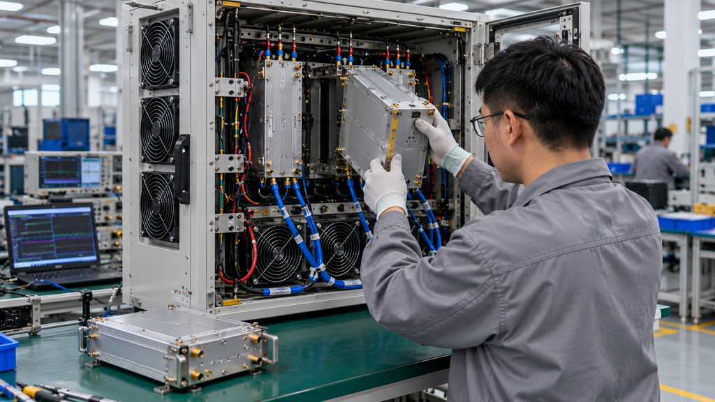
To separate a bad module from a multi PA cabinet fault, treat module identity, physical position, branch, RF route, and enable sequence as controlled variables. Track which of those variables the repeatable fault follows.
If the event follows the same S/N across compatible positions, investigate that module more deeply.
If the fault remains with one slot or DC branch while compatible modules are moved through that position, investigate the cabinet path.
If it follows a thermal zone, control channel, or RF route, follow that shared path.
If it appears only with one module combination, keep the interaction itself at the center of the investigation. If changing enable order changes the result while the active combination stays the same, control or startup timing deserves more attention.
Swap and relocation tests are useful only when the positions are safe and technically compatible. Frequency, RF load, DC supply, cooling, control interface, protection settings, and other material operating boundaries must remain reasonably comparable. Otherwise the relocation creates a new test condition rather than isolating the original one.
A stable fault-following pattern sets direction. “Follows S/N” means investigate that module. “Follows slot” means investigate the slot and its associated paths. Neither observation, by itself, proves damaged PA hardware or a failed cabinet component.
6. What Evidence Should a Simultaneous-Operation Fault Record Contain?
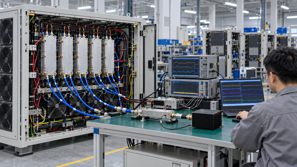
Another engineer should be able to reconstruct the combination event from the fault record.
Preserve the cabinet or configuration identity; each participating module model, S/N, slot, and channel; active combination; frequency and waveform; Pout condition; enable order and timestamps; Actual Pin at the defined PA input reference plane; PA-terminal Vdc and Idc; relevant temperature data; cooling and cabinet state; Pout at its defined reference plane; FWD / REV / VSWR where applicable; Alarm and protection state; controller state; and test duration.
Also record the first changed measurement, the domain selected for specialist investigation, the corrective action, and the result of a retest using the same reproducing combination.
Every measurement should retain its source and reference location. Keep data from different times or configurations separate unless the timing and configuration can be validly correlated.
A final Alarm screenshot preserves the symptom but usually loses the sequence needed for diagnosis. Individual PA PASS reports have the same limitation at system level. Combination-operation evidence should remain traceable to the participating modules and the wider acceptance record.
If the record does not contain the active combination, a usable timestamp relationship, or a first changed measurement, leave the cross-domain cause unresolved and collect the missing synchronized evidence.
What Should the RFQ and Acceptance Plan Require for Simultaneous Operation?
The RFQ and acceptance plan should define the simultaneous operating states the system is actually required to support.
Specify the approved combinations and any prohibited combinations. If the system is not designed for every PA to operate at once, define the maximum approved simultaneous combination instead.
For each required state, define the enable rule, frequency, target Pout at the defined PA output reference plane, duty, test duration, PA-terminal supply boundary, per-channel current evidence, cooling and thermal state, RF load or antenna path, FWD / REV / VSWR evidence where applicable, Alarm and protection behavior, and the condition that qualifies as system Ready.
Traceability should connect each system event to the participating modules. Require module count, model, S/N, slot, and channel identity together with the synchronized combination record and a same-combination retest after corrective action.
The system-level record complements the individual unit reports. Broader shipment, S/N, and acceptance evidence can remain under the C-UAS RF PA acceptance checklist.
Projects do not need to test combinations that their operating rules prohibit. They do need defined conditions and evidence for every combination they are genuinely allowed to use.
If the allowed combinations, Pout, duty, or enable rule have not yet been defined, put those fields into the RFQ before simultaneous-operation acceptance is claimed.
For an RF SKYPOWER engineering and RFQ review, send us the project-defined module count and identities, frequency, Pout with its reference plane, duty conditions, approved simultaneous combinations, single/combination/all-on behavior, PA-terminal Vdc and Idc, cooling and thermal state, RF-path evidence, and Alarm or control timing.
Our engineering team can use that package to identify the next investigation boundary. If the isolation work shows that the current RF PA configuration does not match the project requirement, we can then review the relevant product or configuration options. An all-on fault by itself is not enough reason to replace a PA or move to a higher-power model.
| Current Finding | Next Route | Boundary |
|---|---|---|
| The first repeatable change clearly points to DC, thermal, RF / EMI / grounding, or control timing. | Continue with the corresponding specialist engineering review. | This routing decision does not by itself prove the final root cause. |
| The isolation work confirms that the current RF PA input, supply, thermal, protection, or system-interface boundary does not match the project requirement. | Review the relevant RF PA modules or configuration options. | An all-on fault alone is not enough reason to replace a PA or move to a higher-power model. |
| The active combination, synchronized timing, or key measurements are still incomplete. | Continue with RF SKYPOWER engineering / RFQ review after the missing evidence is collected. | Do not recommend a specific product or claim a root cause until the system event can be reconstructed. |
Conclusion
Start the retest with the smallest repeatable fault combination, then work back through the same measured boundaries that were present when the fault appeared. Keep the active combination, frequency, Actual Pin, Pout, duty, RF load, PA-terminal Vdc/Idc, cooling state, and measurement reference planes traceable throughout the sequence.
Once one domain shows a repeatable first change, move into the corresponding specialist investigation and repeat the original fault combination after corrective action. If the sequence changes, reopen the cross-domain investigation rather than forcing the previous explanation onto a different event.
For an RF SKYPOWER engineering/RFQ review, provide the module model/S/N/slot/channel identities, approved simultaneous combinations and enable rule, RF operating conditions, PA-terminal supply and current evidence, cooling and thermal state, RF-path measurements, Alarm/protection and system-Ready behavior, synchronized event record, and same-combination retest result. That gives our engineering team enough traceability to decide which technical boundary should be reviewed next without claiming a root cause that the evidence has not established.