










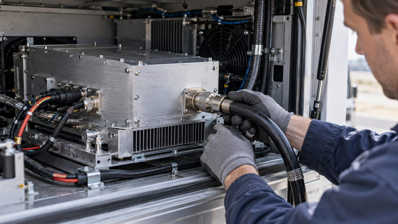
A vehicle-mounted C-UAS RF PA can return to its approved operating configuration after transport, vibration, or reinstallation only when the integrator has evidence that the affected mechanical, DC, control, and RF conditions remain acceptable. That evidence must apply to the installed module, its current connections, and the project’s required operating conditions.
Post-transport checks for a vehicle-mounted C-UAS RF amplifier start with the last accepted configuration. An earlier PA test report may still apply to the module, but a reconnected feeder, altered power connection, or changed mounting arrangement can require new verification.
The integration team must establish which previous results remain valid, which interfaces need retesting, and whether the available evidence supports release. Each finding should trace back to the transport or vibration event, the current installation, and an applicable acceptance requirement.
1. What Has Changed Since the Last Accepted Vehicle Configuration?
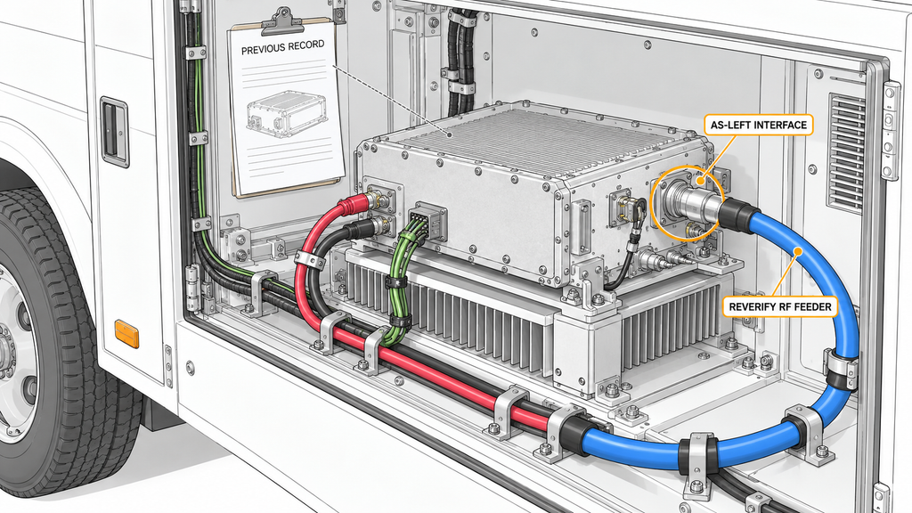
Start with the equipment and operating conditions covered by the previous acceptance.
The reference configuration should identify the PA model and serial number, relevant hardware and control revisions, mounting arrangement, thermal interface, DC and return connections, RF port assignments, cable assemblies, and controller settings.
Compare those records with the vehicle’s actual installation after transport or maintenance.
Record whether the equipment underwent routine transportation, an abnormal vibration event, removal and reinstallation, or replacement of a cable or controller. These events can affect different parts of the earlier acceptance evidence.
A unit-level RF report may still support an unchanged PA under its documented test conditions. However, if an external feeder was disconnected and reconnected, the report cannot establish the condition of the reassembled RF path.
Changes to the power distribution or control interface may also affect the relevance of earlier RF measurements. Remounting the amplifier can alter the cooling conditions under which its previous stabilized results were obtained.
Earlier post-vibration RF PA verification can establish how a tested module performed under a defined exposure and measurement condition. A factory RF amplifier test report tied to the PA serial number documents unit-level test conditions; it does not clear vehicle interfaces altered after transport. The current reviewer must establish whether that evidence still applies to the installed vehicle.
If equipment identity, connection history, configuration revision, or test conditions are unknown, the old and current configurations cannot yet be treated as equivalent.
Record the applicable scope of each historical result and identify the interfaces it does not cover. Unresolved differences remain open until the required evidence is available.
2. Which Mounting, RF Cable, and Harness Interfaces Require Reinspection?
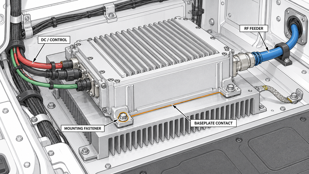
Inspect the interfaces that transport, vibration, handling, or maintenance may have disturbed.
Before manipulating RF or electrical connectors, personnel should place the equipment in its approved maintenance state, disable RF output, and isolate applicable supplies according to the installation procedure.
The mounting inspection covers fasteners, brackets, enclosure attachment, grounding or bonding connections, and the contact between the PA baseplate and its cooling structure where applicable.
A module may remain firmly attached even though its thermal contact pressure or mounting condition has changed. If the change affects cooling, earlier stabilized RF measurements may no longer represent the installation. Use the approved mechanical documentation for fastener and mounting requirements.
Check whether RF connectors were remated, cable supports moved, routing changed, or mechanical strain transferred to the PA ports.
A cable can appear undamaged and still require RF verification. Visual inspection and continuity testing cannot establish its frequency-dependent insertion loss or reflection behavior.
DC and control connections have different requirements from coaxial assemblies. A low-voltage harness crimp and strain-relief check evaluates power, return, and control connections under the applicable electrical and mechanical conditions. RF connectors require separate verification appropriate to the signal path.
The affected function determines the next check. A disturbed DC connection may require loaded power measurements. A remated RF connector may require installed-path measurements. A changed mounting interface may require confirmation that the previous thermal acceptance conditions still apply.
Repairing a connection or remounting the PA restores the intended physical arrangement. Where that work affects an accepted electrical or RF condition, the corresponding performance evidence must also be reconfirmed.
3. Which Vehicle Power Events Must Be Rechecked at the PA Input?
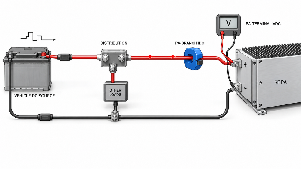
Select vehicle power checks according to the installation changes and operating events relevant to the current acceptance decision.Use the model-specific RF amplifier power supply requirements to identify the permitted PA-input voltage range and any stated transient limits, then record the actual voltage during the selected vehicle events.
A disconnected DC cable, replaced converter, changed distribution connection, unexplained restart, or recorded RF disturbance may justify renewed measurements. The project operating profile determines which events must be represented. Transportation alone does not require every vehicle to undergo an identical transient test.
Measure Vdc at the PA power terminals under the specified operating load. A supply display or unloaded source-side reading cannot establish the voltage received by the amplifier during changing current demand.
Current requires a separate measurement definition. Idc at an identified PA input-branch measurement point should be associated with the active channels, operating state, waveform or duty cycle, and relevant thermal condition. It must not be confused with the total current of other equipment sharing the vehicle supply.
Relevant events may include vehicle starting, converter or distribution switching, simultaneous equipment loads, and transitions into or out of PA operation, depending on the approved platform.
Keep the event identity with the PA-terminal voltage measurements, defined current readings, and corresponding controller or protection states.
A DC-related RF output drop may originate in the source or distribution path, especially when the symptom appears only during a specific load transition. The electrical measurements must support that interpretation before the RF stage is treated as defective.
A steady voltage reading taken after the event cannot rule out a transient. If a required transition was not captured with adequate time resolution, the supply condition remains unverified until suitable evidence is available.
Use the approved product and project requirements to determine the applicable voltage limits, transient conditions, and permitted protection responses.
4. How Should DC, Control, and RF Events Be Correlated?
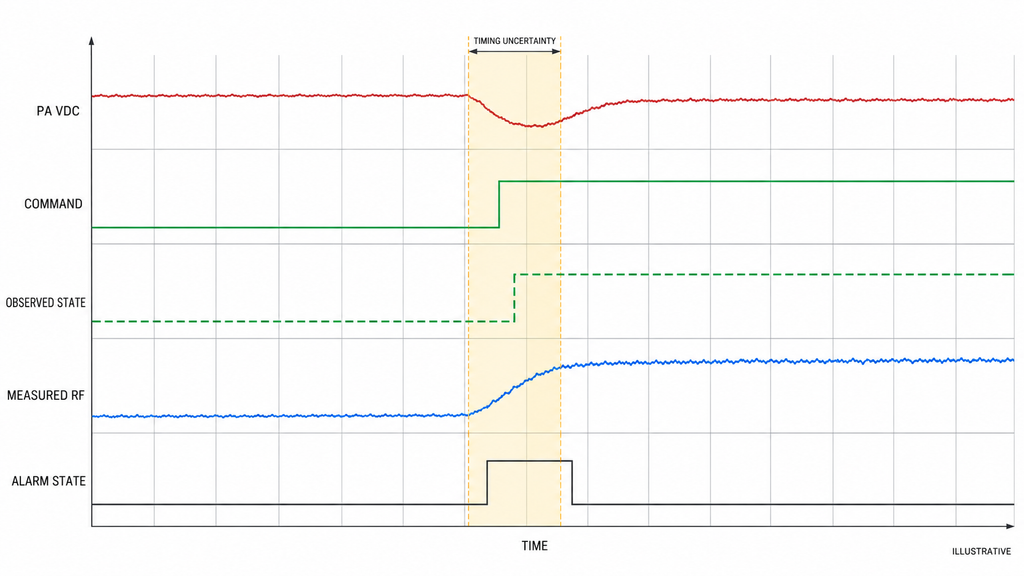
DC, control, and RF records can support a return-to-service decision when they refer to the same event and installed configuration.If the installed model supports it, time-align RF power amplifier alarm monitoring records with PA-input voltage and measured RF output for the same vehicle event.
Tie each relevant trace to the transport or maintenance event, current configuration revision, PA serial number, and operating transition under investigation.
Keep the measurement boundaries distinct:
- PA-terminal voltage and source-side voltage.
- PA input-branch current and total vehicle current.
- Controller command and observed enable or operating state.
- Fault indication and measured fault-trigger condition.
- Internal forward/reverse-power telemetry and externally measured, corrected RF output.
The records may come from different instruments or controllers. Before interpreting their sequence, establish how timestamps, sampling intervals, clock references, reporting delays, and sensor behavior affect their alignment.
A controller log may report a state change later than an RF instrument even when the underlying physical events occurred in a different order. Averaged RF telemetry may also miss a brief disturbance captured by a faster electrical measurement.
If timing uncertainty could change which event appears to occur first, the records cannot establish the sequence.
Different event sequences require different investigations
The following conditional examples show how the observations affect the next engineering action. They are not measured case studies or confirmed failure diagnoses.
PA-terminal voltage changes before control inhibition and RF reduction.
With adequate timing alignment and comparable operating conditions, this sequence supports investigating the power-delivery path first.
The next checks may involve the source, distribution components, return path, and affected connections. Timing alone cannot identify a defective cable or establish that the PA has no internal fault.
A controller command or observed operating-state change precedes RF reduction while the relevant DC condition remains acceptable.
Investigate control intent, actual state feedback, and the approved transition behavior.
The engineer must determine whether RF output followed a valid command, an unintended state change, or a protection response. A logged command does not prove that the hardware had already reached the commanded state.
An RF-path or reflected-power-related indication changes without a corresponding confirmed DC disturbance.
Investigate the installed RF path, sensing boundary, load condition, and protection logic.
A reflected-power alarm cannot independently establish the actual mismatch at the antenna or identify the PA as the fault source. The relevant frequency, measurement boundary, and protection configuration still need verification.
The same reasoning applies to multi-PA vehicles. A change in one power branch may coincide with an alarm in another module. Shared DC bus interaction must be evaluated against the active loads and defined branch measurements before attributing the disturbance to an individual amplifier.
When the event sequence cannot be established
An event remains unresolved when the necessary records use incompatible time references, lack sufficient resolution, omit critical states, or cannot be compared under the relevant conditions.
Document which observations support the current interpretation, which possible causes remain unconfirmed, and what evidence is missing. The investigation may require a controlled repeat verification.
Relate those findings to the physical change that prompted the review.
For example, an intermittent RF disturbance recorded after a DC connector was remated justifies examining that interface. The timing association does not establish that the connector caused the disturbance.
The release review should preserve the relationship among the vehicle event, as-left configuration, time-aligned measurements, and engineering disposition. Any relationship that cannot be established must remain unresolved.
5. Which RF Results Need Repeat Testing—and at What Reference Plane?
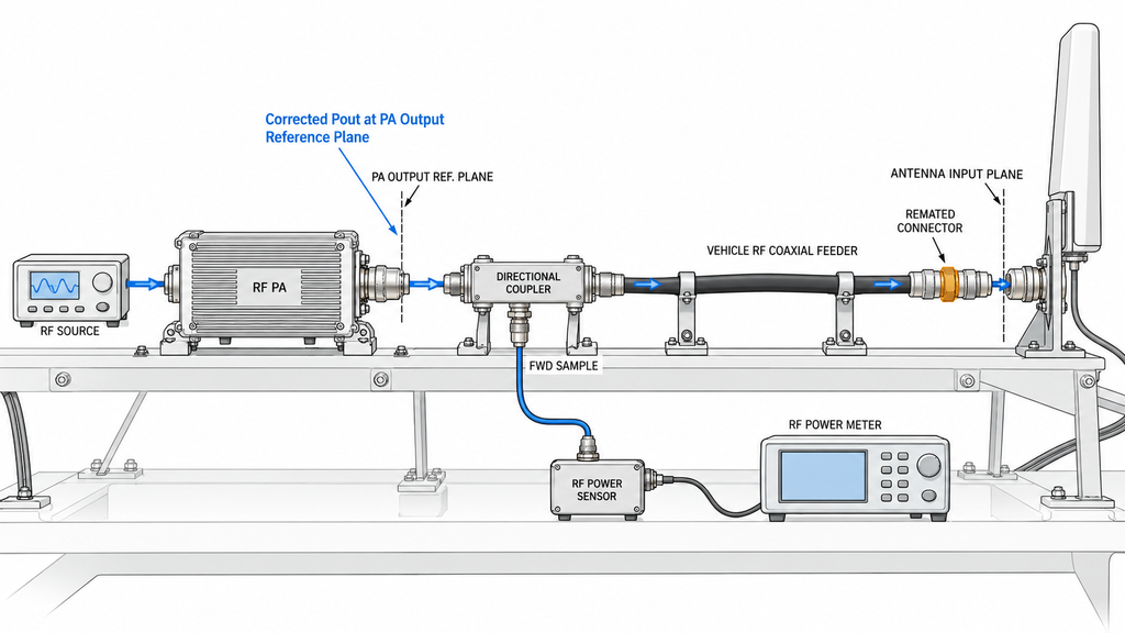
The changed interface determines which RF evidence needs renewed verification.
If an external feeder or antenna connection was remated while the PA remained unchanged, verify the affected installed RF path. Where the acceptance plan requires it, record RF power amplifier output VSWR at the defined PA-port reference plane; an antenna-end reading is not interchangeable with that result. Repeating only a matched-load PA-port measurement would leave the changed downstream connection unverified.
If the PA’s DC input connection changed, earlier RF data may remain comparable only when the required supply condition is established for the current installation. An unexplained output reduction during a vehicle load event may require coordinated DC and RF measurements.
A change to the mounting or cooling interface may affect the validity of earlier stabilized operating data. Replacing the PA or relevant hardware may require unit-specific RF evidence for the current module.
Changes to the control interface or protection configuration may also require confirmation of the corresponding RF operating state, even when steady output appears normal.
For repeated PA measurements, identify the exact reference plane.
Corrected Pout at the PA output reference plane differs from power measured at a cabinet output, feeder end, or antenna input.
A meaningful comparison requires sufficiently aligned frequency, Actual Pin at the PA input reference plane, waveform and duty cycle, fixed or adjusted drive method, PA-terminal DC condition, RF load, cooling, thermal state, measurement method, and corrections.
The generator setting is not automatically Actual Pin. A raw coupler reading is not automatically corrected PA-port output. A cold single-frequency result cannot establish stabilized full-band performance.
The RF power measurement boundaries in vehicle C-UAS installations also prevent a lower antenna-end reading from being mistaken for insufficient PA output without accounting for the downstream path.
A matched dummy-load result can support PA performance under its documented conditions. Installed-path acceptance requires evidence for the actual feeder, connectors, and load.
If historical and current measurements do not sufficiently align, they are not comparable yet. Identify the mismatched conditions before repeating the verification needed to resolve the affected question.
The approved specification or project procedure must define the acceptance limits. There is no universal post-transport RF tolerance.
6. When Can the Vehicle Return to Service, and When Must It Be Held?
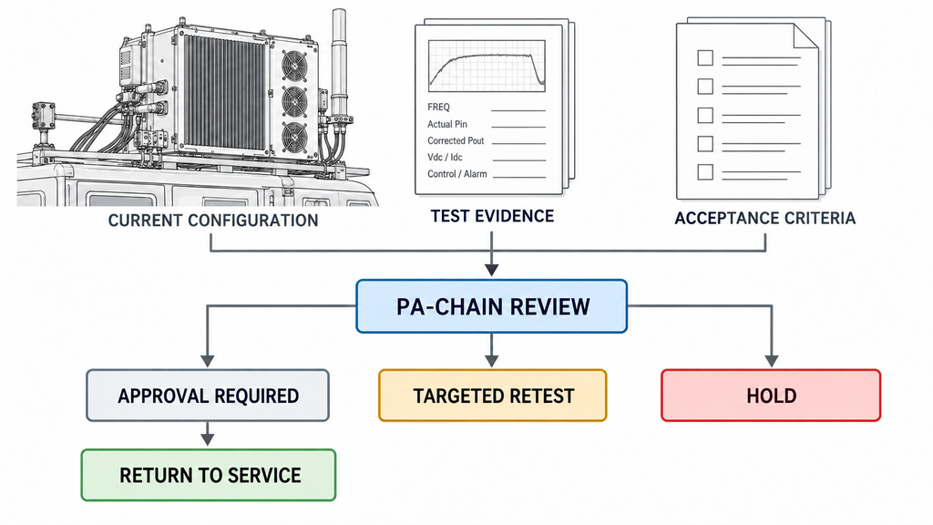
The installed PA chain can be considered for return to service when its current configuration is identified, the required post-transport checks are complete, and the applicable RF amplifier acceptance test criteria are satisfied using valid evidence for that installation.
Previous evidence may be retained where its documented scope still applies. Changed interfaces require verification of the affected conditions.
Use the following matrix to identify what evidence each change requires and which decision remains open.
Vehicle post-transport recommissioning evidence matrix
| Change or event | Check and reference boundary | Evidence to retain | Conditions required for comparison | Next-action decision basis | Responsible owner |
|---|---|---|---|---|---|
| Transport or vibration without a reported configuration change | PA identity, installation revision, mounting, and interface condition | Event ID, PA S/N, as-left revision, inspection record, previous acceptance reference | Same relevant equipment, interfaces, and approved conditions | Retain historical evidence after confirming configuration equivalence; investigate discrepancies | Vehicle integration lead |
| Remounting or altered thermal contact | Fasteners, mounting interface, baseplate contact, and cooling arrangement | Installation inspection, approved mounting reference, affected thermal verification record | Approved mechanical arrangement and relevant stabilized operating condition | Correct deviations and repeat affected verification where previous conditions no longer apply | Mechanical integration lead |
| RF cable or feeder reconnection | Affected RF connector and installed downstream reference plane | Cable/port identity, connection record, applicable installed-path measurement | Same defined RF path, frequency, reference plane, load, and correction basis | Verify the changed path; a PA-port report alone cannot establish its acceptance | RF integration lead |
| DC distribution change or vehicle power event | Vdc at PA terminals and Idc at the defined input-branch measurement point | Event-linked voltage/current records, load state, relevant limit reference | Comparable vehicle event, active loads, operating state, and measurement locations | Retest if the required event was not captured; hold if a mandatory condition remains unverified or outside limits | Vehicle power engineer |
| Restart, alarm, or protection transition | Command, observed state, protection indication, DC condition, and RF response | Time-referenced logs, acquisition details, event sequence, unresolved exception | Adequate timestamp alignment, signal definitions, and required operating state | Confirm required transition and recovery behavior; hold the affected function if unresolved | Control integration lead |
| Changed or unexplained RF result | Corrected Pout at the defined PA output reference plane, with separate installed-path evidence where required | Current-unit RF record, Actual Pin, corrections, test conditions, baseline reference | Comparable frequency, drive, waveform, load, supply, cooling, thermal state, and method | Retain, repeat, or hold the comparison according to approved limits and evidence applicability | RF test engineer |
Each listed owner is accountable for the assigned verification and its supporting evidence. Other specialists may contribute, but the responsibility for each check must remain clear.
A separately designated approval authority makes the final PA-chain release decision.
The release record should connect the vehicle configuration and event ID with the PA serial number, supporting evidence, test results, acceptance criteria, unresolved exceptions, responsible reviewers, approval decision, and date.
Three dispositions are possible.
Return to service: The installation is confirmed, required evidence applies to the current configuration, all mandatory conditions are satisfied, and the designated authority approves the affected PA-chain function.
Targeted retest: An interface or operating condition has changed, but unaffected historical evidence remains valid. Additional verification addresses the change under the approved procedure.
Hold: A mandatory requirement is not met, a relevant fault remains unresolved, required evidence is missing, or the available measurements cannot support a valid comparison.
A hold may result from incomplete records, an unverified interface, an unresolved event, or a confirmed equipment problem. The responsible engineer must establish the reason before approving corrective action or replacement.
A shipment-stage C-UAS RF PA acceptance record can establish the identity and documented performance of a delivered unit. Vehicle recommissioning also requires evidence that the current installed interfaces and operating conditions are acceptable.
PA-chain approval does not establish complete C-UAS system readiness or authorize operation of the vehicle-mounted RF installation. System-level safety, installation acceptance, and operating authorization remain subject to the applicable procedures and responsible authorities.
Conclusion
A vehicle-mounted C-UAS RF PA may return to its approved operating state after transport or vibration when the integrator confirms the current installation and demonstrates that the affected mechanical, DC, control, and RF conditions meet the applicable requirements.
The review determines which historical evidence still applies, where targeted verification is needed, and which unresolved conditions prevent PA-chain release.
Model-specific voltage limits, vibration thresholds, RF tolerances, product suitability, and formal acceptance values require the relevant specifications and measurement evidence. A previous vibration PASS or serial-number-linked module report does not automatically validate the reinstalled vehicle.
Before contacting a supplier, the integration team should assemble the event record, current configuration revision, affected interfaces, comparable measurements, acceptance limits, and unresolved exceptions.
If that review identifies a need to reconsider module selection or replacement, the RF SKYPOWER RF power amplifier module range provides information about available product families. A product listing cannot establish vehicle compatibility, delivered-unit performance, or post-transport acceptance.
For module-specific engineering review, contact the RF SKYPOWER engineering team with the PA model and serial number where available, vehicle DC architecture, installation changes, frequency and waveform requirements, cooling and load conditions, relevant DC/control/RF records, measurement reference planes, and project acceptance criteria.
RF SKYPOWER can review requirements and supporting evidence within the confirmed PA module scope. The authorized integration team retains responsibility for the final vehicle-level release decision.