


To check RF Power Amplifier Harness Crimping, verify whether the crimped terminal can keep supply, ground, control, and protection-feedback paths stable under current, heat, vibration, and repeated handling. A harness may look clean, pass a quick continuity check, and fit the connector housing, yet still create voltage drop, local heating, intermittent enable signals, alarm jumps, or unstable status feedback after installation.
This is the real customer choice behind the topic: should you approve a harness because it looks correct, or should you verify whether the crimped connection stays electrically and mechanically stable in the finished module? The conflict is simple: appearance proves basic assembly condition, but contact resistance, pull strength, strain relief, and vibration behavior decide whether the RF Power Amplifier remains stable during C-UAS system operation.
For RF Power Amplifier modules for C-UAS integration, harness crimping should be reviewed as part of field reliability, not as a low-value accessory process. The module may depend on the same harness for 28V DC input, GND return, enable control, alarm feedback, VSWR status, temperature status, voltage status, communication lines, fan control, and cabinet-level interconnection. In low-altitude security and C-UAS system integration, these paths must stay stable after assembly, shipment, installation, and long-duty operation.
1. How to Check RF Power Amplifier Harness Crimping Quality
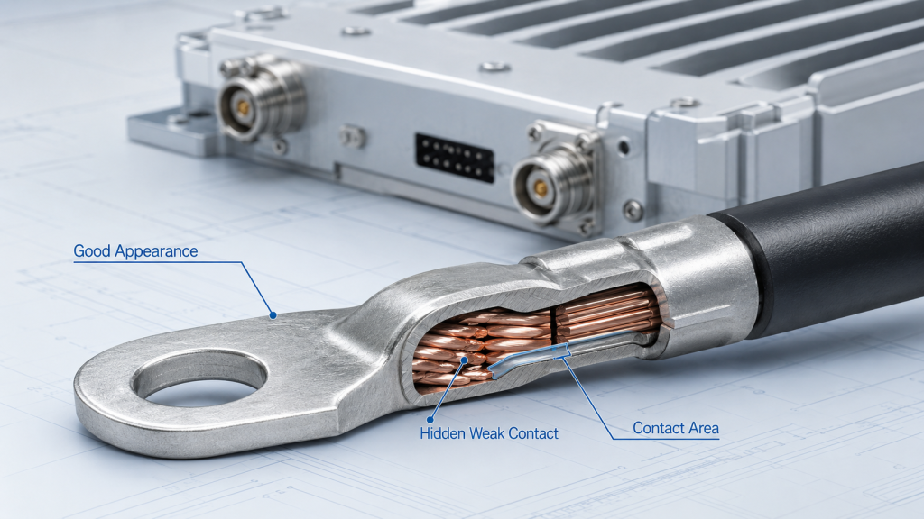
A good-looking crimp is not enough for RF Power Amplifier Harness Crimping reliability because appearance cannot confirm contact resistance, conductor compression, pull strength, or vibration behavior. A terminal may look properly formed while the internal conductor grip is weak, the crimp height is wrong, the copper strands are damaged, or the insulation support is not carrying cable strain.
Here’s the engineering point: many crimping failures are not visible until the harness is exposed to high current, heat, cable movement, or vehicle vibration. In practical field review, harness reliability includes stable supply, ground return, control feedback, and repeatable mechanical retention, not only a clean terminal shape.
What Can Appearance Confirm?
Visual inspection is still the first gate. It helps remove obvious defects before the harness is installed in the module or cabinet.
It can usually find:
- Terminal deformation
- Exposed conductor
- Insulation damage
- Wrong wire color or label
- Missing lock feature
- Incorrect connector housing
- Obvious assembly damage
What Can Appearance Miss?
Visual inspection cannot prove that the conductor crimp area is properly compressed or that contact resistance remains stable under current. It also cannot prove that the insulation crimp can absorb cable pull without transferring stress into the electrical contact area.
Key Takeaway: A clean-looking crimp only proves that obvious defects were not seen; it does not prove field stability under current, heat, vibration, and handling.
| Wrong Assumption | Better Check | Why It Matters |
|---|---|---|
| Good appearance means reliable crimp | Check pull strength and resistance | Finds hidden weak contact |
| Continuity means stable connection | Test under load and movement | Finds intermittent faults |
| Terminal fit means process quality | Check crimp height and section | Confirms compression quality |
| Harness is only an accessory | Review supply and feedback role | Prevents false PA diagnosis |
This table helps engineers avoid approving a harness only because it looks acceptable on the bench.
2. When Are Simple Crimp Checks Acceptable?
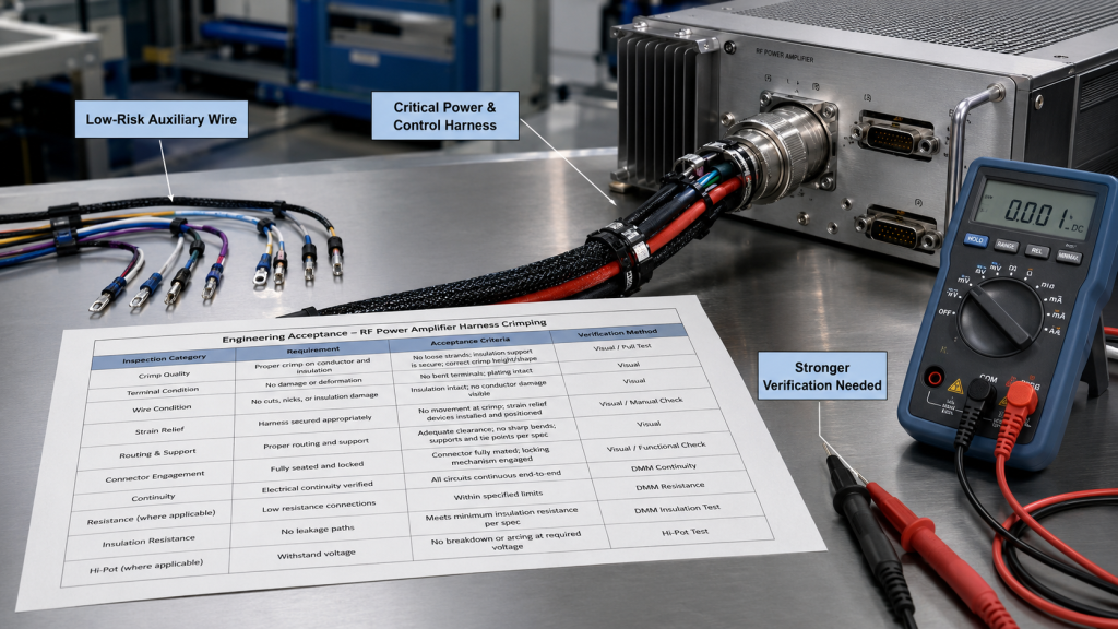
Simple crimp checks are acceptable for RF Power Amplifier Harness Crimping only when the wire is low-risk, low-current, easy to replace, and not part of a critical supply, ground, control, or protection-feedback path. Not every wire needs the same test depth. A non-critical indicator wire in a lab sample does not carry the same risk as a 28V supply line or alarm feedback wire in a fielded module.
The better check is simple: inspection depth should match the function of the harness. If the wire can affect module power, enable behavior, status reporting, or field maintenance decisions, a basic appearance and continuity check is not enough.
Which Wires Are Lower Risk?
Some wires can use lighter inspection because they do not directly decide module operation or field protection behavior.
Examples may include:
- Low-current auxiliary lines
- Non-critical indicator wiring
- Temporary lab prototype wiring
- Easily replaceable service leads
- Non-shipment test fixtures
- Short-term demonstration harnesses
Where Does the Exception Stop?
The exception stops when the harness carries 28V power, GND return, enable control, alarm feedback, VSWR status, temperature status, voltage status, or communication lines. These wires can change whether the RF Power Amplifier starts correctly, remains stable at full load, or reports the right fault state.
Key Takeaway: Simple checks are acceptable only for low-risk auxiliary wires; power, ground, control, and protection harnesses need stronger crimp verification.
| Harness Function | Simple Check Fit | Stronger Verification Needed |
|---|---|---|
| Indicator wire | Medium to high | Low |
| Lab-only temporary lead | Medium | Medium |
| 28V supply harness | Low | High |
| Alarm or status feedback | Low | High |
This table helps procurement teams avoid applying the same inspection depth to every harness.
3. What RF Power Amplifier Harness Crimping Must Prove
Crimping quality becomes a field risk in RF Power Amplifier Harness Crimping when the harness carries supply current, ground return, control signals, protection feedback, or operates under vibration, heat, cable strain, or repeated handling. The risk is not only total failure. The more difficult issue is intermittent behavior that appears after transport, installation, temperature change, or cabinet vibration.
This is where system integrators should pay attention: a weak crimp may pass factory continuity testing and still create field instability after the cable is bent, pulled, heated, or shaken. The symptom may look like a PA problem, but the root cause may sit in the terminal-to-wire interface.
Which Conditions Trigger Strict Control?
Strict crimp control is needed when the harness is part of a path that affects module operation or diagnostic decisions.
High-risk conditions include:
- 28V DC supply
- GND return path
- Enable signal
- Alarm feedback
- VSWR status
- Temperature status
- Voltage status
- Vehicle-mounted systems
- Long-duty operation
- Remote maintenance sites
Why Are Intermittent Symptoms Harder?
A failed wire is easy to find. A marginal crimp is harder because it may work while stationary and fail only under load, vibration, heat, or cable movement.
Key Takeaway: Harness crimping becomes a field stability risk when intermittent contact can change module power, control, protection feedback, or remote diagnostic decisions.
| Field Trigger | Crimping Risk | Typical Symptom |
|---|---|---|
| High current | Voltage drop and heat | Output instability |
| Vehicle vibration | Contact movement | Alarm jump or restart |
| Heat cycling | Resistance shift | Status drift |
| Repeated handling | Terminal loosening | Intermittent control |
This table helps field teams link unstable symptoms to harness conditions before replacing the PA module.
4. How RF Power Amplifier Harness Crimping Affects Voltage
Contact resistance changes RF Power Amplifier Harness Crimping risk because a small resistance at the terminal can become voltage drop, local heat, supply instability, or protection behavior under high-current operation. A crimp may pass continuity testing at low current, yet still become unstable when the PA draws current during full-load RF output.
Here’s the practical risk: cable size may be correct, but module-side voltage can still drop if the crimped terminal adds resistance. This is why supply checks should not stop at the power source; they should include the terminal, harness, connector, and module input. Related supply issues are also discussed in RF Power Amplifier supply voltage reviews.
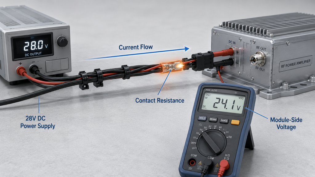
What Happens at the Terminal?
A weak crimp reduces the effective metal-to-metal contact area between conductor and terminal. Under load, that resistance can create both voltage loss and heat.
Possible results include:
- Lower module-side voltage
- Local terminal heating
- Higher current stress
- Output instability
- Voltage alarm events
- Early protection behavior
Why Is Ground Also Important?
GND harness crimping is just as important as the positive supply path. A weak ground return can create unstable reference behavior, noise sensitivity, status drift, or false alarm interpretation.
Key Takeaway: Contact resistance from weak crimping can turn a correct cable size into an unstable supply path at the module side.
| Problem Area | What Weak Crimping Changes | Better Starting Point |
|---|---|---|
| Supply voltage | Module-side voltage drop | Measure at module input |
| Local heat | Terminal temperature rise | Check crimp resistance |
| Ground return | Reference instability | Inspect GND crimp path |
| Protection behavior | Alarm or derating | Review supply under load |
This table helps engineers separate cable-size problems from terminal-contact problems.
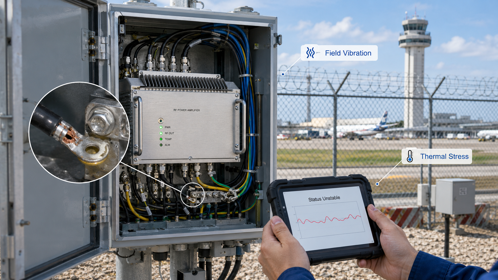
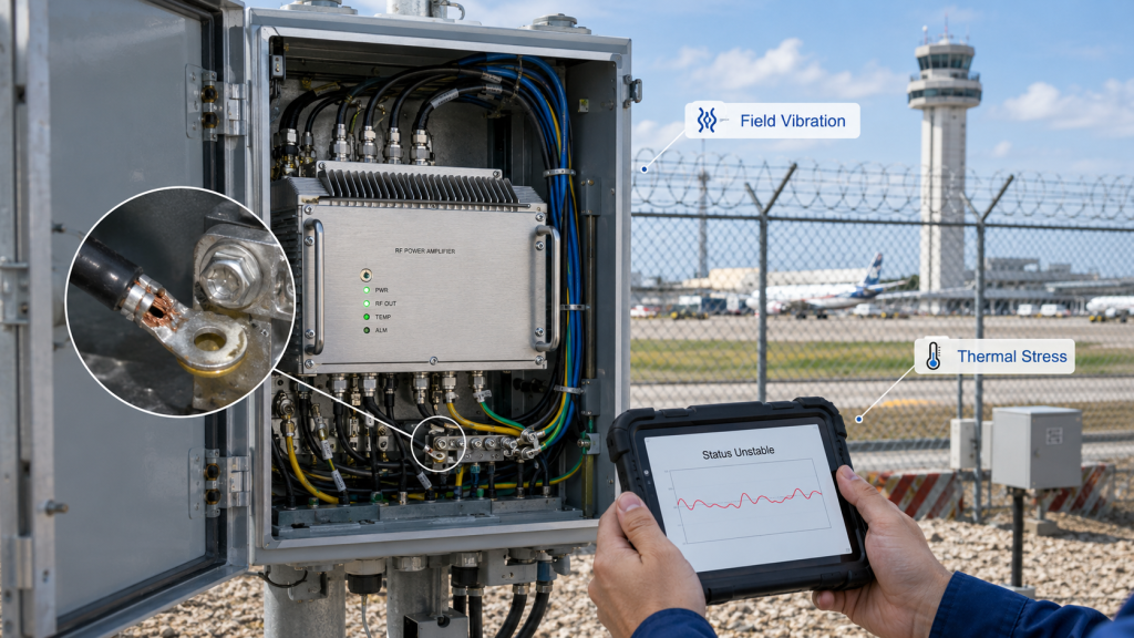
5. What RF Power Amplifier Harness Crimping Reveals in Field
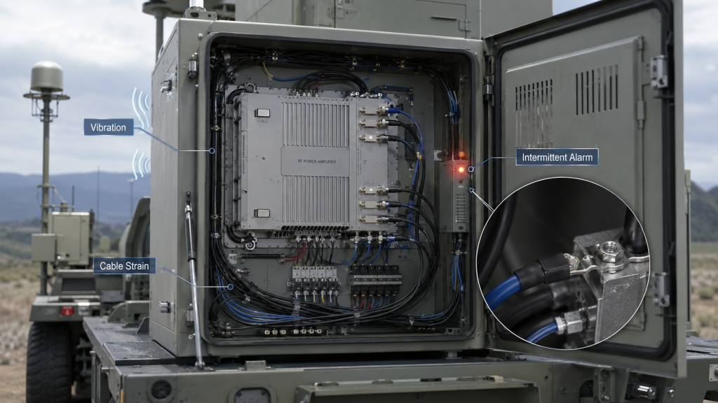
Real field conditions reveal weak RF Power Amplifier Harness Crimping because vibration, thermal cycling, cable strain, and multi-module operation can turn marginal terminal contact into intermittent module instability. A harness that behaves correctly on a static bench may not behave the same way after vehicle movement, cabinet heat, installation stress, or repeated service handling.
Here’s the field reality: weak crimping often does not look like a harness problem at first. It may appear as a PA restart, voltage alarm, enable dropout, temperature status jump, unclear VSWR status, or unstable control feedback.
Which Deployment Scenarios Expose Weak Crimps?
Different C-UAS deployments stress harnesses in different ways. The scenario matters because the same crimp quality may be acceptable in a lab but risky in a moving or remote system.
Typical examples include:
- Vehicle-mounted C-UAS systems with vibration and cable movement
- Outdoor fixed cabinets with heat, humidity, and thermal cycling
- Airport perimeter systems that require long unattended operation
- Critical infrastructure sites with limited maintenance windows
- Multi-module cabinets with many supply and feedback harnesses
- Transported systems installed after shipping stress
Why Does This Affect Maintenance?
In an airport counter-UAS RF deployment, an intermittent alarm or voltage feedback line can create unnecessary maintenance calls because the remote team may first suspect the antenna, PA, controller, or power supply. For critical infrastructure sites, a harness-related alarm jump may also trigger unnecessary site visits because remote operators cannot immediately distinguish PA failure from supply, control, or crimp-contact instability.
Key Takeaway: Field conditions expose weak crimping by adding vibration, heat, strain, and diagnostic complexity that a short bench test may not include.
| Deployment Condition | Crimping Weak Point | Field Result |
|---|---|---|
| Vehicle platform | Vibration at terminal | Intermittent enable or alarm |
| Outdoor cabinet | Heat cycling | Resistance drift |
| Critical infrastructure | Remote alarm ambiguity | Unnecessary site visit |
| Multi-module rack | Many harness paths | Harder fault isolation |
| Transported system | Handling stress | Post-shipment instability |
This table helps system teams decide when harness stress testing should be part of acceptance.
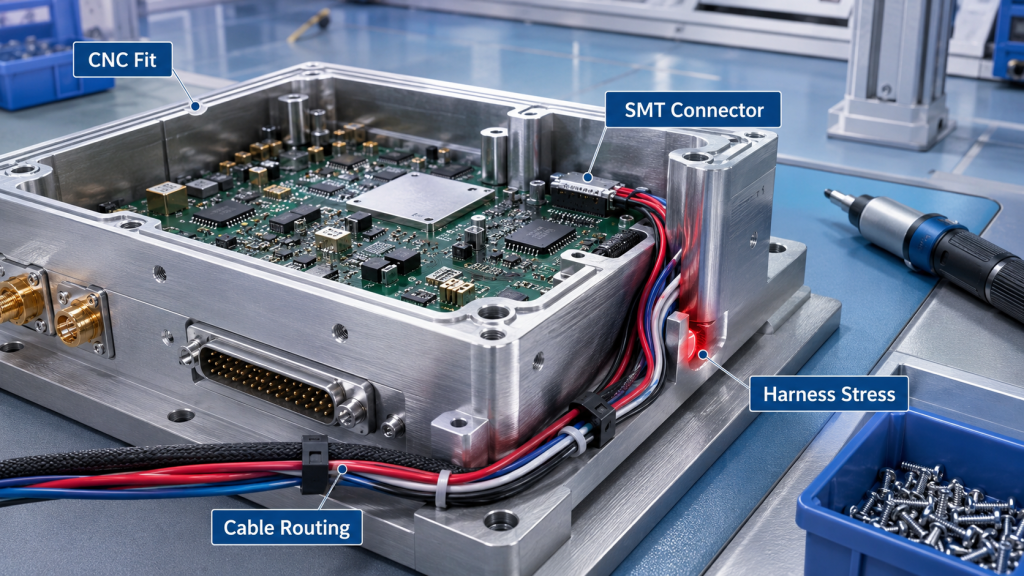
6. How Do Assembly Processes Interact With Harness Crimping?
Assembly processes interact with RF Power Amplifier Harness Crimping because CNC fit, SMT connector placement, cleaning control, assembly torque, thermal process, and harness routing can all change cable stress and connector stability. Crimp quality is not only the terminal pressing step. A good crimp can still become unreliable if later assembly steps force the harness into tension, bending, compression, or vibration.
The point is not that every assembly process creates a crimping defect; the point is that later assembly can load the crimped terminal in a way the crimping station never tested. Source-factory manufacturing review should therefore treat harness crimping as part of the full module assembly path, not as an isolated wire-preparation task.
Which Processes Can Add Stress?
Several manufacturing and assembly choices can change how the harness behaves after the module is closed or installed in a cabinet.
Examples include:
- CNC enclosure window alignment
- SMT connector location
- Cleaning residue near connectors
- Screw torque and board stress
- Thermal interface compression
- Harness clamp position
- Cable bend radius
- Connector locking direction
Why Does Process Coordination Matter?
If the connector is slightly misaligned, the harness may stay pulled after assembly. If the cable is too short, the terminal may carry mechanical load. If the cable is too long and not fixed, vibration may keep moving the terminal.
Key Takeaway: Harness crimping reliability depends on the full assembly process, because later mechanical stress can weaken an otherwise acceptable terminal connection.
| Assembly Factor | Harness Effect | Better Check |
|---|---|---|
| CNC opening offset | Cable pressure or bend | Fit check after closure |
| SMT connector position | Poor cable exit angle | Routing review |
| Torque variation | Board or connector stress | Controlled torque record |
| Thermal assembly pressure | Harness interference | Final mechanical check |
This table helps factories review the harness as part of the finished module, not only as a separate part.
7. Why Do Crimp Design and Strain Relief Matter?
Crimp design and strain relief matter in RF Power Amplifier Harness Crimping because the conductor crimp should provide electrical contact while the harness structure absorbs pull force, vibration, bending, and repeated handling. If the conductor crimp carries mechanical stress, the connection may degrade even when the terminal was initially pressed correctly.
This is the design issue many teams miss: a terminal is not supposed to be the cable’s shock absorber. The insulation crimp, connector lock, harness clamp, bend radius, and routing path should protect the conductor crimp from repeated movement.
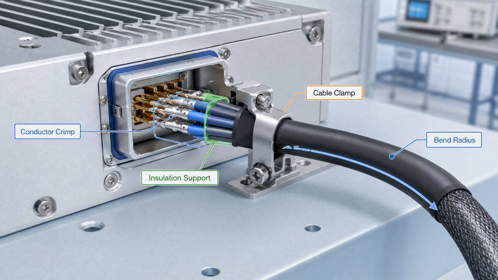
What Should Each Area Do?
A reliable crimped harness divides electrical and mechanical work between different areas.
Typical roles include:
- Conductor crimp: electrical contact
- Insulation crimp: mechanical support
- Connector lock: retention in housing
- Harness clamp: vibration control
- Bend radius: fatigue reduction
- Routing path: strain control
What Happens When Strain Relief Is Weak?
If the harness has no strain relief, cable motion can reach the terminal. If the cable is too short, the terminal may be pulled. If the cable is too long and loose, it may swing in vibration.
Key Takeaway: A reliable crimp is not only a pressed terminal; it is a controlled wire, terminal, connector, clamp, and routing system.
| Design Element | Purpose | Failure If Ignored |
|---|---|---|
| Conductor crimp | Electrical contact | Resistance change |
| Insulation crimp | Strain support | Wire movement |
| Connector lock | Terminal retention | Intermittent contact |
| Harness routing | Stress control | Fatigue or pull load |
This table helps buyers evaluate harness reliability beyond the terminal appearance.
8. How to Test RF Power Amplifier Harness Crimping
Tests prevent crimp-related RF Power Amplifier Harness Crimping failures when they verify pull strength, section quality, contact resistance, vibration behavior, thermal response, and control-signal stability together. A one-time continuity test is only the lowest gate. It cannot prove that the terminal will remain stable during full current, cabinet heat, vehicle vibration, or service handling.
This is where test evidence matters. A stable RF Power Amplifier control interface depends not only on logic design but also on harness reliability for enable, alarm, VSWR status, temperature status, and voltage feedback.
Which Evidence Should Be Collected?
A complete harness review does not always require every test for every wire, but critical paths need more than appearance. The most useful evidence does not only say “pass”; it explains what was proven and what still needs module-level confirmation.
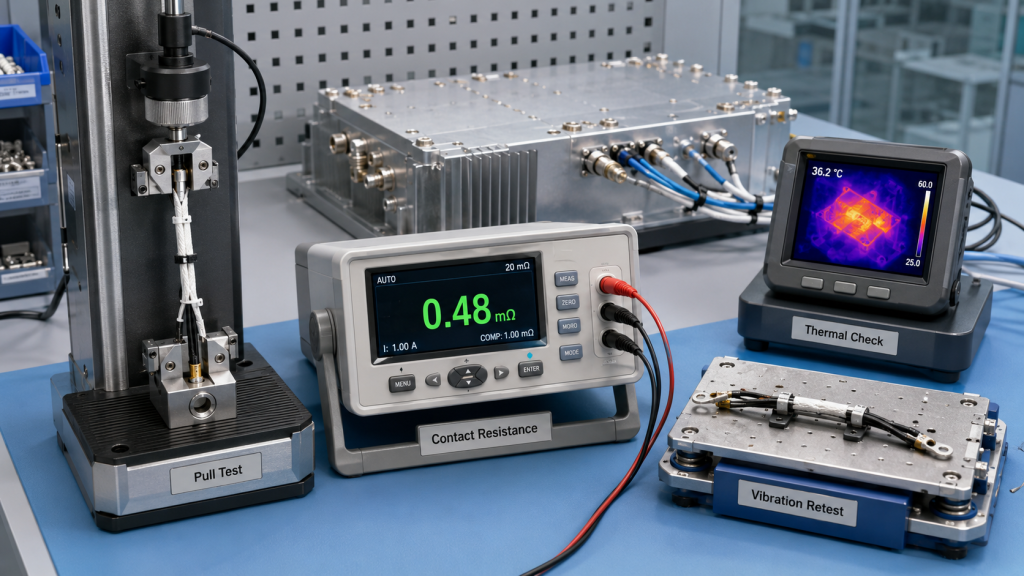
Useful checks include:
- Visual inspection
- Pull test
- Section analysis
- Contact resistance check
- High-current temperature check
- Vibration retest
- Thermal-cycle retest
- Insertion and locking check
- Control-signal validation
What Should Be Retested After Stress?
After vibration, thermal cycling, insertion, or handling, the same electrical and control functions should be checked again. This catches marginal crimps that work before stress but drift afterward.
Key Takeaway: Crimp testing should prove both initial quality and post-stress stability, especially for supply and protection-feedback harnesses.
| Evidence Item | What It Proves | What It Still Needs |
|---|---|---|
| Pull test | Terminal retention | Contact resistance under load |
| Section analysis | Conductor compression | Post-vibration stability |
| Contact resistance | Electrical path quality | Thermal behavior at current |
| Vibration retest | Intermittent weakness | Long-term batch consistency |
| Control-signal test | Feedback stability | S/N-linked report evidence |
This table helps engineering and procurement teams treat crimp validation as an evidence chain, not a single pass/fail check.
9. What Buyers Should Ask About RF Amplifier Harness Crimping
Buyers should ask how RF Power Amplifier Harness Crimping is controlled, tested, stressed, traced, and linked to supply stability, control feedback, and shipment records before quotation. Asking only whether the harness is included is too shallow. For high-power RF modules, the harness can affect voltage, grounding, enable behavior, alarm feedback, and protection-state interpretation.
The better check is simple: if the supplier cannot describe how crimp quality is verified, the buyer cannot know whether the harness is a controlled manufacturing process or only a fitted accessory.
What RFQ Information Matters?
A useful RFQ should ask about both the harness design and the crimping process.
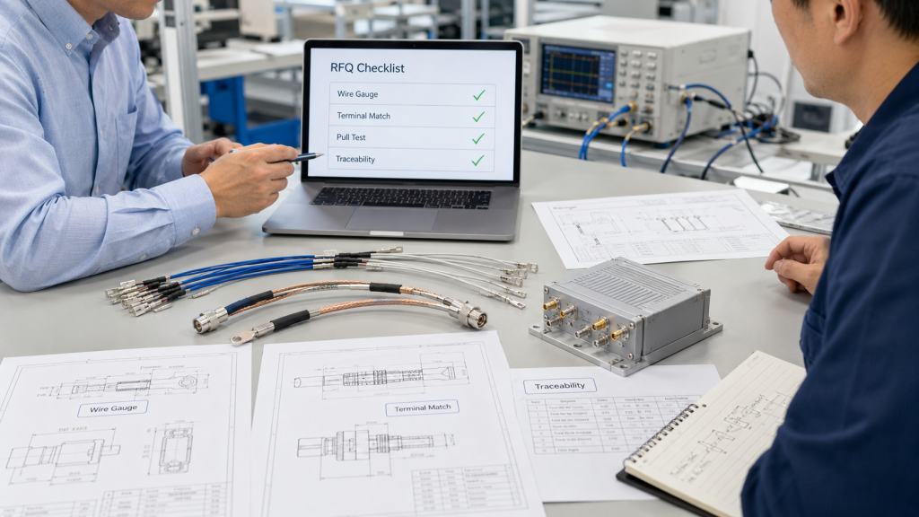
Buyers should confirm:
- Wire gauge and conductor material
- Terminal model and wire match
- Crimp tooling or process control
- First-article confirmation
- Pull test method
- Contact resistance control
- High-current temperature check
- Vibration or stress retest
- Harness routing and strain relief
- Traceability to module shipment
What Are Warning Signs?
Vague answers are a problem. “Continuity tested” does not prove contact resistance, pull strength, strain relief, vibration stability, or high-current behavior.
Key Takeaway: RFQ review should treat harness crimping as a supply and control reliability question, not only a cable accessory question.
| RFQ Question | Strong Answer Should Include | Warning Sign |
|---|---|---|
| How is crimping controlled? | Tooling and acceptance criteria | “By operator experience” |
| How is it tested? | Pull, resistance, stress checks | Continuity only |
| How is it traced? | Harness batch and module link | No record |
| What changes trigger retest? | Terminal, tooling, routing change | No process rule |
This table gives procurement teams a practical way to screen supplier process maturity.
10. How Can You Decide If Crimping Is Field-Ready?
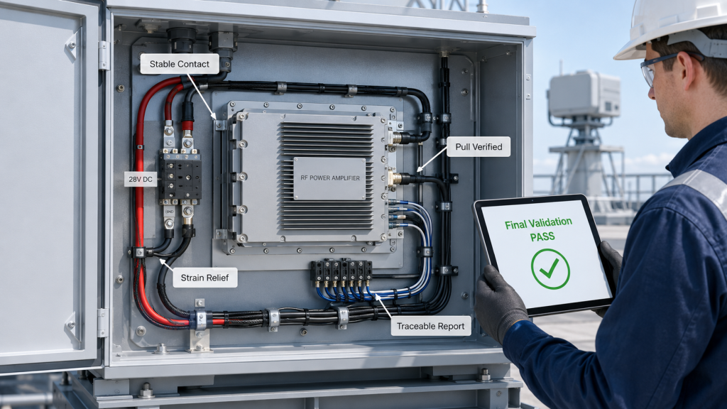
You can decide if RF Power Amplifier Harness Crimping is field-ready only when electrical contact, mechanical retention, strain relief, vibration behavior, supply stability, control feedback, and traceable test evidence are verified together. A harness should not be approved only because it fits the connector or passes static continuity.
For engineering and procurement review, the final question is practical: can this harness keep the module stable under the real current, heat, vibration, handling, and diagnostic conditions of the project? If the answer depends on assumptions, the harness needs more verification before shipment.
What Should the Final Review Confirm?
The final decision should connect harness function, stress condition, test evidence, and module-level behavior.
A practical final checklist includes:
- Harness function
- Current or signal risk
- Terminal-to-wire match
- Crimp height and appearance
- Pull strength
- Contact resistance
- Module-side voltage
- Control feedback stability
- Strain relief and routing
- Traceability to shipment
Where Does Source-Factory Review Help?
As a source factory for RF Power Amplifier modules and C-UAS core components, RF SKYPOWER can review harness crimping together with CNC fit, SMT connector position, cleaning control, assembly torque, thermal process, control-signal testing, S/N traceability, and repeatable shipment evidence.
Key Takeaway: Field-ready crimping is proven when the harness remains electrically stable, mechanically retained, stress-controlled, and traceable after realistic module-level checks.
| Final Review Area | Field-Ready Condition | Warning Sign |
|---|---|---|
| Electrical contact | Stable resistance under load | Voltage drop at module |
| Mechanical retention | Pull and lock verified | Terminal movement |
| Strain relief | Cable stress controlled | Harness pulls terminal |
| Test evidence | Results linked to shipment | No traceable record |
This table helps buyers decide whether harness crimping is ready for real C-UAS integration or only bench assembly.
FAQ
Can a harness pass continuity but still fail in the field?
Yes. Continuity proves a basic electrical path, but it does not prove low contact resistance, pull strength, vibration stability, or high-current performance.
What should I check before accepting RF Power Amplifier harnesses?
Check terminal-to-wire match, crimp quality, pull strength, contact resistance, strain relief, connector locking, module-side voltage, and control feedback after stress.
How do I know if voltage drop comes from crimping?
Measure voltage at the module input under load, then inspect the terminal, harness, connector, and ground return path. A weak crimp can create voltage loss even when the cable size is correct.
When should harness crimping be retested?
Retest after terminal changes, tooling changes, harness routing changes, vibration exposure, thermal cycling, repeated insertion, repair, or any field symptom involving voltage, enable, alarm, or status feedback.
Is poor crimping the same as interface soldering failure?
No. Interface soldering affects solder joints and PCB connection points, while harness crimping affects the mechanical and electrical connection between wire and terminal. Both can cause intermittent control signals, but the root causes are different.
Conclusion
Wire harness crimping may look like a small manufacturing detail, but it can directly affect RF Power Amplifier field stability. Supply voltage, ground return, enable signals, alarm feedback, VSWR status, temperature status, and voltage feedback all depend on stable crimped terminals. When contact resistance, pull strength, strain relief, or vibration reliability is weak, the result may not be immediate failure, but voltage drop, local heating, intermittent control feedback, false alarms, or protection behavior that becomes difficult to diagnose in the field.
For system integrators, RF engineers, and procurement reviewers, the practical lesson is clear: harness crimping should be reviewed as part of RF Power Amplifier reliability, not as a low-value accessory process. Appearance, pull strength, section quality, contact resistance, vibration behavior, module-side voltage, control feedback, and repeatable test evidence should be checked together before shipment and field integration.
RF SKYPOWER supports source-factory manufacturing review by connecting harness crimping quality with CNC fit, SMT connector position, cleaning control, assembly torque, thermal process, control-signal testing, S/N traceability, and repeatable shipment evidence. If your project needs to reduce voltage drops, intermittent control signals, or vibration-related harness issues during C-UAS integration, you can contact us today to review your RF module manufacturing and harness reliability requirements.
Reliable RF Power Amplifier field stability starts before the module is powered on, when the harness is crimped, stressed, tested, and traced as part of the complete C-UAS RF system.