











RF amplifier output power spread for one wideband module is the difference, in dB, between its highest and lowest corrected Pout values across an approved frequency set under one comparable measurement contract. A defensible acceptance decision also requires every frequency point to meet its own minimum Pout; a small spread cannot rescue a module that is low everywhere.
That result is valid only when the same module, power definition, Actual Pin rule, PA output reference plane, load condition, DC state, control mode, and relevant thermal state apply across the dataset. Fixed-drive, leveled, and compression-limited traces answer different questions and must not be combined into one spread value.
The main evidence gap is rarely the subtraction itself. It is whether the points represent comparable measurements and whether the project has defined both an absolute output requirement and a spread limit. Those two boundaries determine whether the result supports acceptance, a hold for missing evidence, or a narrower engineering review.
1. Define Output Power Spread for One Wideband Module
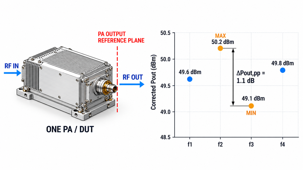
Output power spread describes the frequency-to-frequency change in absolute RF output from one identified amplifier module. Let Pout(fi) be the corrected output power at frequency fi, referred to the approved PA output reference plane. For the approved set of frequencies, the peak-to-peak spread is:
ΔPout,pp = max[Pout(fi)] − min[Pout(fi)]
This definition must name the power quantity. CW average power, modulated average power, peak-envelope power, output at 1 dB gain compression (P1dB), and saturated output power (Psat) are not interchangeable. A spread result that mixes these quantities has no single engineering meaning.
Output power spread is also not gain flatness. Gain depends on both input and output power, so operating gain at a frequency is G(fi) = Pout(fi) − Pin(fi) when both values use compatible dBm definitions and reference planes. When the decision is how G(fi) varies, the applicable specialist method is gain flatness measurement and acceptance, not this Pout metric.
The scope is one module across frequency. It is not the difference among several PA modules, the difference among channels with different output targets, or the distribution among units in a production lot. Those dimensions require different identities, limits, and evidence.
The buyer’s first output should therefore be a measurable statement such as:
For the identified module and approved frequency set, calculate the peak-to-peak difference among corrected Pout values measured at the PA output reference plane under the specified signal, Actual Pin rule, load, DC, control, and thermal conditions.
If the module identity, frequency set, power definition, or output reference plane is missing, stop before reporting a formal spread.
2. Lock Comparable Pout Conditions Across Frequency
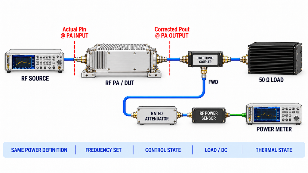
The arithmetic is valid only after the measurement conditions are aligned. A signal generator set to the same displayed level at every frequency does not necessarily deliver the same Actual Pin at the PA input reference plane. Source cables, switches, attenuators, fixtures, and driver stages can have frequency-dependent gain or loss.
For a fixed-drive result, calibrate or measure Actual Pin at the PA input reference plane and keep it within the approved tolerance at every point. On the output side, record the raw instrument reading, the applicable frequency-specific correction, its sign convention, and the corrected Pout at the named PA output reference plane. Do not apply a nominal loss twice or reuse a correction from one frequency across the full band without supporting characterization.
The following conditions must remain the same or be explicitly controlled:
- signal and power definition;
- approved frequency set and point order;
- Actual Pin rule and input reference plane;
- raw-to-corrected Pout method and output reference plane;
- load or permitted VSWR condition;
- PA-terminal voltage and current measurement boundary;
- manual-gain, automatic level control (ALC), or other control state;
- cold, transitional, or defined stabilized thermal state;
- dwell, settling, and relevant test-sequence rule; and
- measurement uncertainty and rounding convention.
The number and spacing of points belong to the project’s RF PA test frequency planning. The spread calculation begins only after that set has been approved. When the project requires high-power data, the point-by-point evidence should come from a condition-matched swept-frequency full-power RF PA test rather than from a low-drive response curve.
Classify the dataset before calculation. It is directly comparable when the material conditions are aligned, partially comparable when a documented difference supports only a narrower conclusion, and not comparable yet when Actual Pin, reference plane, correction, load, or thermal state is unresolved. “Not comparable yet” is a valid result; it prevents a precise-looking spread from being built from incompatible points.
3. Calculate Peak-to-Peak Spread and Minimum Output Separately
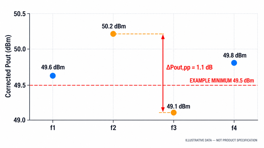
Keep the point-by-point values as the primary record. Identify the maximum corrected Pout, the minimum corrected Pout, and the frequency of each. When the measurements are in dBm, subtract the minimum from the maximum directly:
ΔPout,pp (dB) = Pout,max (dBm) − Pout,min (dBm)
When the source data are in watts, use the power ratio:
ΔPout,pp (dB) = 10 log10(Pmax / Pmin)
Do not subtract two watt values and label the result in dB. Do not mix average and peak power, or CW and modulated results, in the same calculation.
Consider an illustrative, model-neutral dataset with corrected outputs of 49.6 dBm, 50.2 dBm, 49.1 dBm, and 49.8 dBm at four approved frequencies. The maximum is 50.2 dBm, the minimum is 49.1 dBm, and the peak-to-peak spread is 1.1 dB. These values demonstrate the calculation only; they are not an RF SKYPOWER product specification or a recommended acceptance limit.
The minimum output remains a separate result. If the project requires at least 49.5 dBm at every point, the illustrative dataset fails that absolute requirement at the 49.1 dBm point even if the project would otherwise accept a 1.1 dB spread. Conversely, every point could meet its minimum while the overall spread still exceeds a separately approved limit.
An average cannot replace this record. A satisfactory average may hide one weak frequency, and a smooth plotted line may hide sparse sampling or a changed drive condition. Acceptance needs the actual frequency values, the extrema, and both decision boundaries.
4. Separate Fixed-Drive, Leveled, and Compression-Limited Results
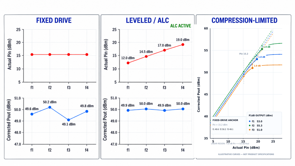
The same formula can summarize different tests, but the resulting numbers do not mean the same thing.
Fixed-drive result. Actual Pin is held at the approved value across frequency. The Pout trace shows how the module responds under comparable input drive. If corrected Pout falls while Actual Pin remains within tolerance, frequency-dependent module behavior becomes relevant. This is the appropriate mode when the project wants the unlevelled response at one input condition.
Leveled or ALC result. Input drive is adjusted at each frequency so the system can reach or hold a target output. This may be valid when the intended equipment operates with leveling, but the report must retain Actual Pin at every point, the permitted Pin range, the ALC or control state, and any minimum gain or linearity boundary. A flat leveled Pout trace proves the leveling result, not the module’s uncorrected fixed-drive spread.
Compression-limited result. A power sweep is performed at each frequency to find output P1dB, saturation, or another approved limiting condition. Every point must use the same stopping definition. A mix of P1dB at one frequency, an arbitrary maximum at another, and a target-output point elsewhere cannot form one valid spread.
Calculate and label each mode separately. If the control mode or Actual Pin history is missing, hold the spread decision until the dataset is reconstructed. Increasing drive at a weak frequency without recording the change may hide reduced gain, limited driver margin, or a different compression state.
5. Explain What Pout Spread Changes in a Multi-Band C-UAS Design
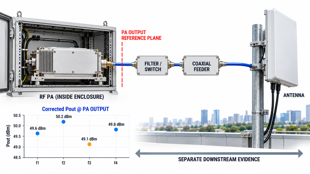
When one wideband module serves several C-UAS operating frequencies, a lower corrected Pout at one point reduces the module-level output margin available at that frequency. It may also require more input drive or coincide with a different DC or thermal state. The immediate decision is whether that weak point still meets the approved PA-output requirement under the defined operating condition.
This is a module-level conclusion. It does not by itself establish power at the antenna input, EIRP, coverage, or C-UAS effectiveness. Downstream filters, switches, cables, connectors, feeders, antenna gain, and mismatch can vary with frequency and require their own evidence.
If the weak point occurs near a required band edge, isolate the band-edge output cause rather than inferring it from the spread alone. The difference may involve Actual Pin, measurement correction, compression, load, PA-terminal voltage, heat, or protection behavior.
The boundary changes again when the project compares different channels or several modules. Each channel may have its own target, RF path, and operating state. That system question belongs to multi-channel RF power consistency, not to a single module’s frequency spread.
Record the weak frequency as a module-output margin risk or as a point requiring downstream verification. Do not turn it into a system-effectiveness conclusion without the missing RF-path and antenna evidence.
6. Apply the Acceptance Limit Without Hiding a Weak Frequency
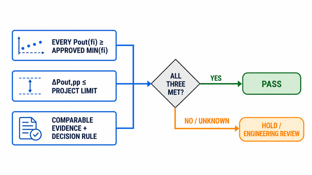
No universal output power spread limit applies to every C-UAS RF PA. The applicable value must come from the product or project specification, RFQ, contract, or approved test plan. Measurement uncertainty, rounding, any guard band, and the retest rule should be agreed before the results are reviewed.
Use three gates together:
| Gate | Check | Pass condition | Failure meaning | Next action |
|---|---|---|---|---|
| Point-level output | Corrected Pout at every required frequency | Every point meets its approved minimum or output envelope | At least one required frequency lacks adequate absolute output | Hold acceptance for that point and investigate or reselect under the approved process |
| Peak-to-peak spread | ΔPout,pp across the approved frequency set | The calculated spread does not exceed the project-approved limit | Frequency variation exceeds the accepted range even if individual points meet minimum output | Review the project limit, drive mode, weak region, and applicable module evidence |
| Evidence and decision rule | Identity, conditions, corrections, uncertainty, and traceability | The dataset is comparable and the approved conformity rule supports the decision | The number cannot support a defensible pass or fail statement | Hold the conclusion and request the missing evidence or repeat the aligned test |
A point-level pass cannot waive an explicit spread requirement, and a small spread cannot waive a weak absolute output. If the project has not defined a spread limit, report the measured peak-to-peak value and its conditions, but do not invent a conformity threshold.
This parameter result should later be considered within the broader C-UAS RF PA acceptance checklist. The wider checklist does not replace this calculation; it determines how the parameter evidence joins identity, configuration, thermal, protection, traceability, and shipment-release requirements.
7. Build the Output Power Spread Acceptance Record
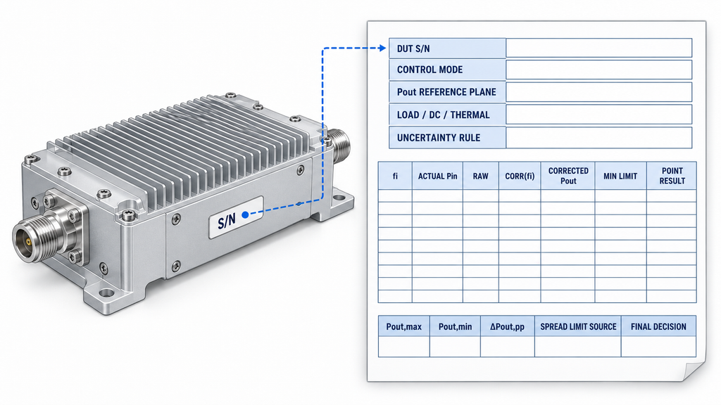
A valid result is a traceable dataset and decision, not one isolated number. Keep the module or evidence identity, the point data, the calculation, the limit source, and the conformity rule together.
Record identity and common conditions
| Record field | Required entry |
|---|---|
| DUT (device under test) / serial number (S/N) or evidence scope | Delivered unit and S/N, qualification sample, representative sample, or other approved scope |
| Module configuration | Model, hardware revision, control state, and relevant configuration version |
| Approved frequency set | Exact tested frequencies and the source of that set |
| Signal / power definition | CW, pulsed, or specified waveform; average, peak, PEP, P1dB, Psat, or other approved quantity |
| Actual Pin rule | Fixed drive, leveled/ALC, or compression-limited method, including the permitted Pin boundary |
| Pout reference plane | Named PA output reference plane and correction boundary |
| Common operating conditions | Load/VSWR, PA-terminal Vdc and Idc boundary, cooling, duty, thermal state, sequence, and dwell rule |
| Uncertainty / decision rule | Approved uncertainty treatment, guard band if used, rounding, and retest rule |
Point-by-point measurement data
| Frequency | Actual Pin | Pin rule / control mode | Raw output reading | Output correction | Corrected Pout | Pout reference plane | Load / VSWR | Vdc / Idc | Thermal state | Minimum Pout limit | Point result |
|---|---|---|---|---|---|---|---|---|---|---|---|
| Project point 1 | Enter measured or calibrated value | Enter mode | Enter raw value and instrument location | Enter frequency-specific value and sign basis | Enter corrected value | Enter named plane | Enter approved condition | Enter loaded values | Enter defined state | Enter approved limit and source | Pass / hold / review under the approved rule |
| Project point 2 | Enter measured or calibrated value | Enter mode | Enter raw value and instrument location | Enter frequency-specific value and sign basis | Enter corrected value | Enter named plane | Enter approved condition | Enter loaded values | Enter defined state | Enter approved limit and source | Pass / hold / review under the approved rule |
| Add every required point | Do not substitute the generator display | Do not mix modes silently | Preserve original reading | Prevent double correction | Use one power definition | Keep the boundary consistent | Record approved differences | Use PA-terminal boundaries | Distinguish cold and stabilized states | Do not invent a universal value | State missing evidence instead of guessing |
Spread summary and final decision
| Summary field | Required entry |
|---|---|
| Pout maximum | Value, frequency, power definition, and measurement mode |
| Pout minimum | Value, frequency, power definition, and measurement mode |
| Peak-to-peak spread | Pout,max − Pout,min in dB |
| Spread limit and source | Project-approved value plus specification, RFQ, contract, or test-plan reference |
| Point-level gate | Confirmation that every required frequency meets its minimum Pout or envelope |
| Evidence-scope gate | Confirmation that identity, conditions, corrections, uncertainty, and traceability support the stated scope |
| Final result | Pass, hold, or engineering review, with the failed gate and affected frequency identified |
For delivered-unit acceptance, the buyer may require one serial number, one point dataset, and one report tied to that unit. A qualification or representative curve remains useful within its stated scope, but it does not automatically prove every shipped unit or a production batch.
The record should also route deeper questions without reproducing their methods. Gain behavior goes to the gain-flatness owner, test-point density goes to frequency planning, high-power data acquisition goes to the swept-frequency test, and multi-module behavior goes to the channel-consistency review.
Product route
After the frequency set, Pout definition, Actual Pin mode, spread and minimum-output limits, load, DC, thermal state, and evidence scope are locked, the wideband RF power amplifier module families can be screened by frequency and power. Product-family coverage does not establish project suitability or acceptance.
What Should the RFQ Define for Output Power Spread?
Define the metric before suppliers generate the data. Otherwise, two technically valid responses may use different input controls, reference planes, thermal states, or power definitions and remain impossible to compare.
| RFQ field | Buyer must define | Why it changes the decision | Supplier evidence required |
|---|---|---|---|
| Module and evidence identity | Product configuration and whether evidence is qualification-, sample-, batch-, or S/N-level | Prevents one dataset from being applied to another scope | Model/configuration identity and applicable traceability |
| Frequency set | Required frequencies, project edges, and any mandatory risk points | Defines which points enter the extrema and spread | Point-by-point data for the approved set |
| Signal and power definition | CW, pulsed, or specified waveform; average, peak, PEP, P1dB, Psat, or other quantity | Prevents unlike output quantities from being combined | Signal setup and reported-power method |
| Actual Pin and control mode | Fixed Actual Pin, leveled/ALC, or compression-limited rule; tolerance and maximum Pin | Determines whether a flat trace reflects module response or active leveling | Actual Pin at every frequency and control-state record |
| Input and output reference planes | PA input plane for Actual Pin and PA output plane for corrected Pout | Separates amplifier behavior from source and measurement paths | Calibration, raw readings, correction terms, and sign convention |
| Load and mismatch boundary | Controlled load, permitted VSWR, or other approved condition | Load changes can alter output and protection state | Load definition plus required forward/reverse or VSWR evidence |
| DC and thermal boundary | PA-terminal Vdc/Idc, cooling, duty, ambient condition, and required thermal state | Keeps electrical and thermal operating states comparable | Loaded DC and time/temperature-linked records |
| Point-level output limit | Minimum Pout or output envelope at each required frequency | Protects the weakest frequency from a misleading average or small spread | Per-point result and limit source |
| Spread limit | Approved peak-to-peak limit and calculation convention | Creates the second acceptance gate | Reproducible extrema and ΔPout,pp calculation |
| Uncertainty and decision rule | Uncertainty treatment, guard band if used, rounding, retest, and borderline-result handling | Determines whether a near-limit result supports conformity | Uncertainty statement and applied decision rule |
| Report requirement | Raw and corrected data, setup identity, evidence scope, and S/N linkage where required | Makes the result reviewable and traceable | Complete output power spread acceptance record |
The RFQ should not prescribe a universal number of frequency points inside this requirement. Complete the separate frequency-point plan first, then place the approved set into the output power spread contract.
Conclusion
Accept output power spread for one wideband RF PA module only when the maximum and minimum corrected Pout values come from the approved frequency set under one comparable signal, Actual Pin rule, PA output reference plane, load, DC, control, and thermal boundary. The final decision must pass both the project-approved spread limit and the minimum Pout requirement at every required frequency.
Do not treat a leveled trace as fixed-drive behavior, or a small spread as proof of adequate output. This framework establishes a module-level acceptance result; product-specific limits, delivered-unit evidence, downstream RF-path behavior, antenna input power, and system effectiveness still require their applicable project evidence.
Complete the point-by-point record, identify the weakest frequency, and resolve any missing condition before supplier approval. Once the metric and boundaries are locked, screen the closest wideband module family by frequency and power. If the spread limit, drive method, load, thermal state, or evidence scope remains open, submit those inputs through an engineering review for output power spread so the RFQ and required evidence can be defined before a specific module is treated as accepted.