










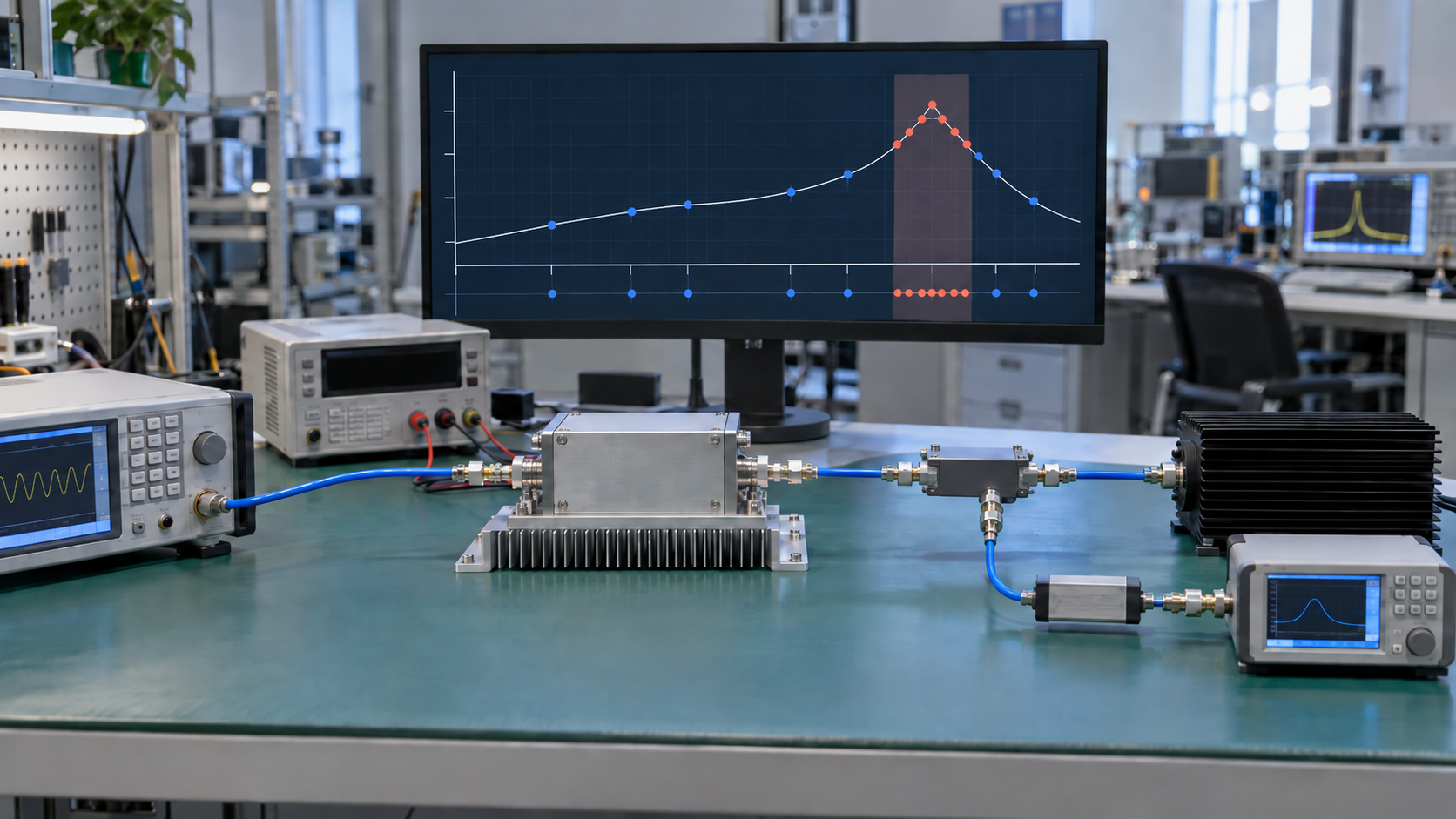
There is no universal number of RF PA test frequencies that fits every C-UAS acceptance plan.
A practical set of RF power amplifier test frequencies comes from two things:
all project-required frequencies that need direct verification, plus extra points wherever an unresolved frequency-dependent risk could change the acceptance decision.
A C-UAS transmitter that uses three fixed channels may need a very different plan from one that can switch across several operating windows. The nominal bandwidth alone does not tell you how many points to test.
Passing several discrete frequencies confirms those points under the stated test conditions. Extending that result across the gaps requires relevant supporting evidence from comparable hardware, operating mode, power level, thermal state, load, and reference plane.
Start by identifying the frequencies the project cannot afford to leave untested.
1. Why Is There No Universal Number of RF PA Test Frequencies?
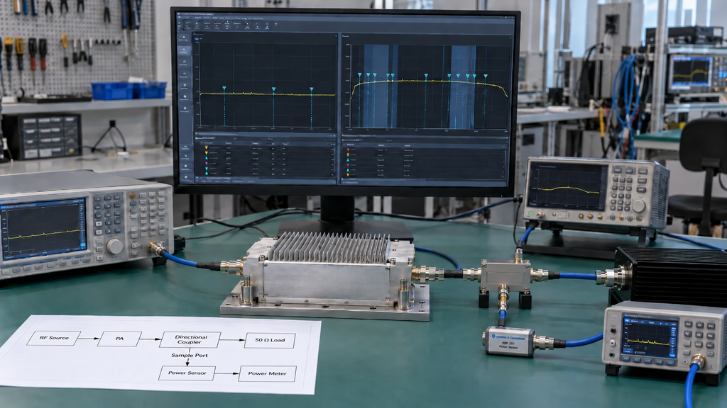
Two RF PAs can have the same stated frequency range and still require different acceptance plans.
A transmitter with a few fixed channels can test those channels directly. A frequency-agile C-UAS system may have dozens of possible operating frequencies or several mission-defined windows. Three widely spaced measurements give useful reference data, but they may leave too much of the required operating space unresolved.
The test count depends on the application:
- Which frequencies can the transmitter actually select?
- Does the system use fixed channels or a broader tuning range?
- Which lower and upper frequencies belong to the project requirement?
- Are there weak regions in existing characterization?
- Does output margin fall in part of the band?
- Could behavior between two tested points change the acceptance result?
Extra points should have a reason. Once every required frequency is covered and the remaining gaps no longer contain a credible unresolved risk for the approved scope, more measurements may add time without adding decision value.
That makes the first practical step clear: identify the frequencies that the project must verify directly.
2. Which Frequencies Are Mandatory Before You Decide the Test Count?
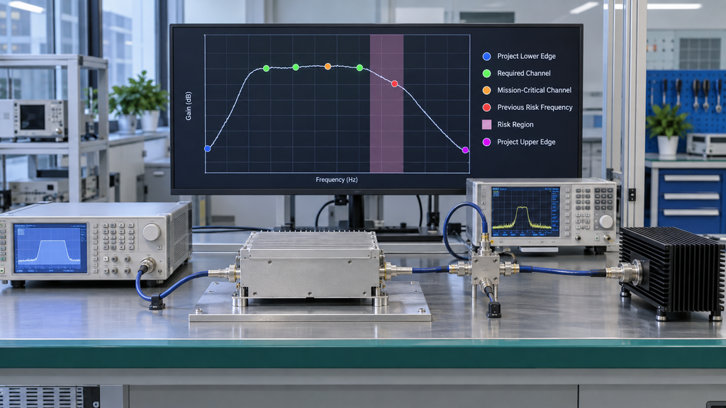
Build the first set of RF PA test frequency points from the system requirement.
For a C-UAS transmitter with selectable channels, the configured operating frequencies deserve priority over a convenient generic low/mid/high set. The same applies to project edges and frequencies already associated with reduced margin or previous anomalies.
The initial set may include:
- required operating channels;
- the lowest required project frequency;
- the highest required project frequency;
- mission-critical channels;
- frequencies with reduced margin in previous measurements;
- known transition or risk regions; and
- frequencies associated with earlier anomalies.
Keep the catalog range separate from the qualification range.
A broadband PA may cover a wider nominal range than the current C-UAS project uses. If the transmitter operates inside a smaller window, the project edges of that window define the immediate acceptance need.
The reverse case matters too. When a project explicitly requires a channel, nearby passing measurements do not remove the need to verify that channel if direct verification is part of the acceptance requirement.
Before adding representative points, the engineer should be able to state:
- the frequencies the system will use;
- the frequencies that require direct verification;
- the real project edges;
- the mission-critical channels; and
- any known frequency-specific concern.
Without those inputs, there is no defensible final test count.
Once the mandatory operating frequencies are defined, the acceptance plan can decide where representative or risk-driven points are still needed. Projects that still need to validate the required operating range can use the RF PA frequency-range verification process separately.
3. When Is a Low–Mid–High Test Set Enough for Acceptance?
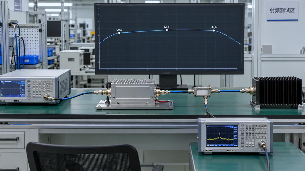
Low-, mid-, and high-frequency measurements are a useful first view across a band. Whether three points are enough depends on what those points represent and what is known about the intervals between them.
When Three Points May Be Enough
A three-point set may support a limited acceptance scope when:
- the points are the actual required operating frequencies, or closely match the approved acceptance scope;
- the system does not need qualification across many additional channels;
- no unresolved edge or local-response concern remains;
- the measurements have adequate margin to the applicable limits; and
- supporting characterization is relevant to the conditions being accepted.
The last condition needs strict control.
Characterization can show where additional acceptance points are likely to matter. It can also support a lower formal test density when it comes from sufficiently relevant hardware or revision and matches the operating mode, power level, thermal condition, load, reference plane, and other conditions that affect the decision.
A dense small-signal sweep from a different configuration cannot stand in for full-power acceptance of the current unit.
The same evidence boundary applies to traceability. When S/N-linked unit acceptance is required, representative characterization can guide the test plan, but it does not replace the measurements required for that delivered unit.
When Three Points Are Not Enough
More coverage is needed when the untested intervals could still hide behavior that matters to the project.
Common triggers include:
- many selectable operating frequencies;
- a requirement to support a broad operating window;
- limited margin at a required band edge;
- local gain or output variation in previous data;
- significant changes in actual Pin across frequency;
- a suspected narrow weak region;
- frequency-dependent hot-state behavior; or
- an unresolved anomaly from earlier testing.
If two points pass, the frequencies between them remain an evidence question. Their status depends on the required scope and the quality of the supporting data.
If the unresolved risk is concentrated near a project edge, the next step is a dedicated RF PA band-edge performance check
Treat low/mid/high as a sampling plan that needs engineering justification, not as a default acceptance rule.
4. When Should You Add More Test Points?
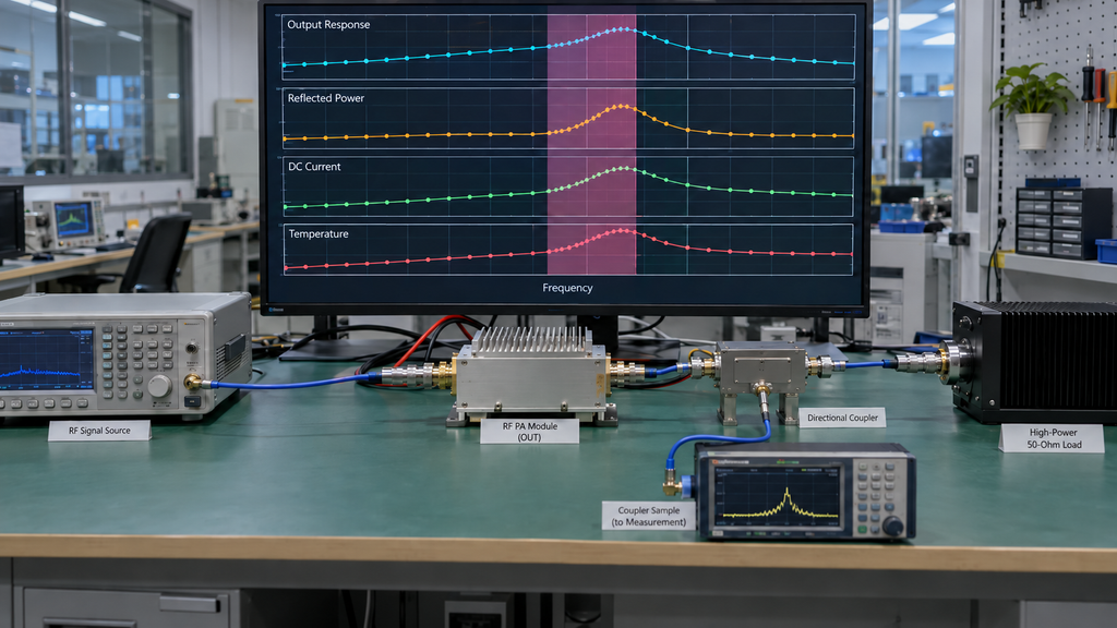
Add another point when an untested interval still contains a plausible frequency-dependent risk that could change the acceptance decision.
Start with the mandatory frequencies and the approved initial sample. Then look for signs that the current spacing is too coarse.
Useful triggers include:
- Pout changes materially between adjacent points;
- output margin approaches the project limit;
- gain shows an unexpected slope or local disturbance;
- actual Pin must change significantly to reach the required Pout;
- FWD/REV, VSWR, DC current, or temperature varies with frequency;
- a matching, filtering, or structural transition falls inside the interval;
- cold and hot behavior diverges in part of the band; or
- a previous anomaly has not yet been bounded in frequency.
For example, two neighboring points may both pass while the second has much less margin. That trend does not prove there is a problem in the interval, but it gives a clear reason to inspect it.
Place the next measurement where it can reduce that uncertainty.
A practical sequence is:
initial test points → unresolved region → higher local frequency resolution → reassessment
Uniform spacing across the whole band may be appropriate for some test plans, but it should come from the measurement objective rather than habit.
Keep diagnostic and acceptance data separate when necessary. A diagnostic point can become acceptance evidence only when its test conditions and evidence scope satisfy the approved acceptance plan.
5. How Should Test-Point Spacing Follow RF Risk?
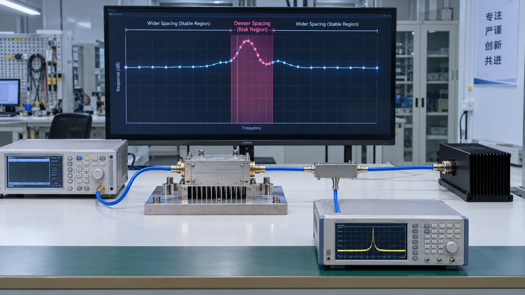
RF PA test point spacing should reflect how much unresolved behavior could still exist between measurements.
No fixed 10 MHz, 50 MHz, 100 MHz, or other step size guarantees adequate RF PA acceptance coverage across different designs and projects.
Start With the Required Frequencies
Use the application to anchor the test plan:
- actual operating channels;
- required lower and upper frequencies;
- mission-critical frequencies;
- known weak points; and
- frequencies explicitly required by the approved test plan.
These frequencies form the fixed framework. Sampling between them should answer a specific risk question.
Add Resolution Around Risk Regions
A stable part of the band with substantial margin may support wider spacing. Regions with less margin or more complex behavior require higher frequency test resolution.
Examples include:
- project edges;
- rapidly changing Pout;
- local gain variation;
- regions requiring noticeably different Pin;
- frequencies near an acceptance limit; and
- areas associated with mismatch, thermal, or historical test concerns.
Existing characterization can help locate these regions, but its scope matters. Data from another unit, revision, operating mode, power level, thermal condition, load, or reference plane can guide investigation without automatically reducing the formal acceptance requirement for the current unit.
Stop When the Remaining Gap No Longer Changes the Acceptance Decision
A frequency plan is ready to stop expanding when:
- all mandatory project frequencies have been covered;
- identified risk regions have enough local resolution to support the decision; and
- further points are unlikely to change the current acceptance or hold decision within the approved test scope.
The stopping point does not require every possible frequency to be measured. It requires the evidence to match the claim being made.
Projects that require a denser full-power sweep should move to the dedicated swept-frequency full-power RF PA testing procedure.
6. What Must Stay Comparable Across Every Test Frequency?
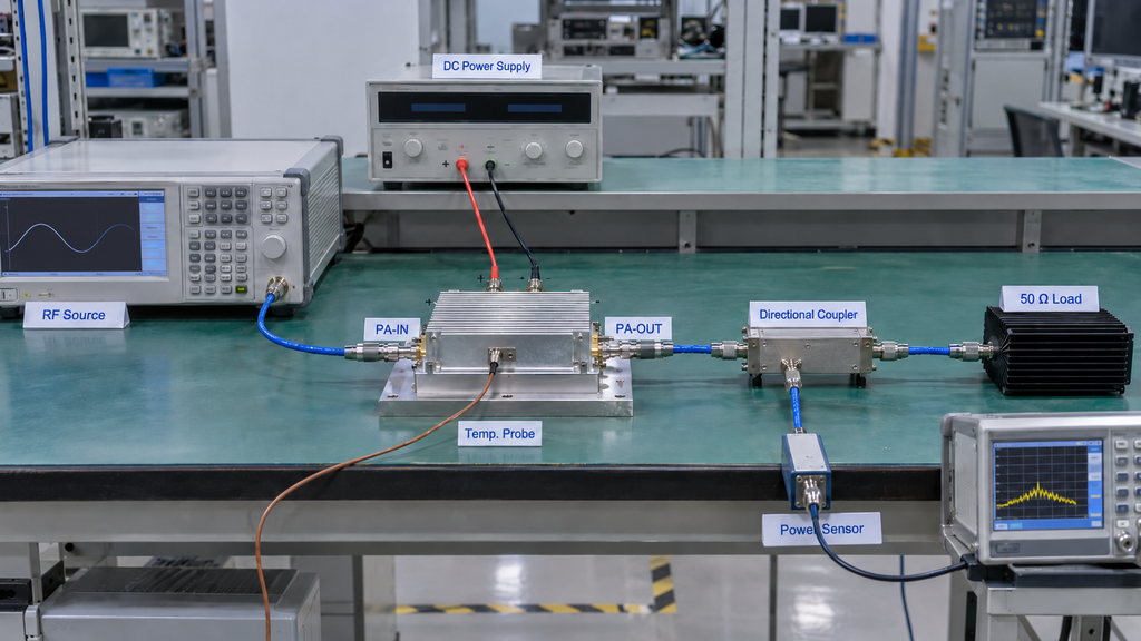
A good frequency plan still fails as evidence if the measurements cannot be compared.
Across formal acceptance points, keep the important test conditions constant or document approved differences:
- waveform and power definition;
- actual Pin at the PA input reference plane;
- Pout reference plane;
- DC supply condition;
- load;
- cooling arrangement;
- thermal state;
- cable and fixture corrections;
- protection state; and
- required dwell or stabilization conditions.
Actual Pin is a common source of error.
The RF generator setting does not necessarily equal the power delivered at the PA input reference plane. Source-path loss can change with frequency, so an unchanged generator setting can still produce different actual Pin at the module.
The same discipline applies at the output. Raw readings taken at one point in the RF chain should not be mixed with corrected Pout values referenced to another plane.
Thermal state also changes the meaning of the comparison. A startup measurement and a hot, stabilized measurement should not be treated as a clean frequency comparison unless the test plan explicitly allows that difference.
If the important conditions cannot be aligned or their differences cannot be accounted for, the data is not comparable yet.
That means the evidence is incomplete for the intended comparison. It does not mean the PA has failed.
If these conditions are aligned and the project needs a full-power frequency sweep, the next step is the full-power swept-frequency test.
7. What Should the RFQ and Acceptance Record Require?
“Test the full band” is too vague for an RFQ.
So is “test low, mid, and high.”
A usable requirement should define the RF PA acceptance test frequencies, why each point matters, the applicable conditions, the required result, and the trigger for adding more points.
The record should also define its evidence scope. Representative characterization, sample inspection, batch evidence, and S/N-linked unit evidence answer different questions.
If delivered-unit traceability is required, specify it before testing so the results can be tied to the applicable S/N and configuration.
Frequency-Point Planning Matrix
Fill in project values · Swipe horizontally to review the full record →
| Test Frequency | Point Type | Why It Must Be Tested | Test Depth | Pin Rule | Acceptance Item | Trigger for Additional Points | Required Record | Traceability Scope |
|---|---|---|---|---|---|---|---|---|
| Enter required operating channel | Required operating frequency | Frequency is directly used by the C-UAS system | Project-defined acceptance depth | Use approved fixed or adjusted Pin rule | Criterion from customer specification, RFQ, or approved acceptance plan | Add nearby points if margin or response changes unexpectedly | Frequency, actual Pin, measured result, relevant test conditions | Sample, S/N-linked unit, batch, or other approved scope |
| Enter required lower project edge | Project edge | Confirms the lowest frequency the project must support | Project-defined acceptance depth | Approved Pin rule | Approved project criterion | Increase local resolution if edge margin is limited or response changes toward the edge | Frequency and complete applicable test conditions | Approved scope |
| Enter required upper project edge | Project edge | Confirms the highest frequency the project must support | Project-defined acceptance depth | Approved Pin rule | Approved project criterion | Increase local resolution if edge behavior changes rapidly | Frequency and complete applicable test conditions | Approved scope |
| Enter mission-critical channel | Critical operating frequency | Channel has direct operational importance | Required acceptance depth | Approved Pin rule | Approved project criterion | Add adjacent points if local performance is abnormal | Complete point record | Approved scope |
| Enter identified risk frequency | Risk point | Existing evidence indicates a possible local weakness or changing response | Increased local resolution | Keep comparable with adjacent points | Relevant approved acceptance item | Continue adding local points while the unresolved region could change the acceptance decision | Comparable local data set | Approved scope |
| Enter anomaly retest frequency | Follow-up point | Determines whether observed behavior is narrow, gradual, or repeatable | Diagnostic or approved acceptance retest | Defined by retest plan | Relevant measured parameter or approved criterion | Expand only while uncertainty remains | Original result, retest conditions, and retest result | Same applicable unit or sample scope |
Fill the matrix with project values. Avoid generic frequency intervals, assumed Pout thresholds, or acceptance limits that were never approved.
The RFQ should state whether Pin stays fixed or may be adjusted by frequency because those methods answer different questions. It should also define the waveform, DC supply, load, cooling, thermal state, Pout reference plane, and measurement corrections wherever they affect comparability.
Once those requirements are fixed, buyers can review the relevant RF power amplifier module families before requesting an engineering evaluation. Product-family frequency and power ratings are useful for initial screening. They are not proof that a specific module satisfies the acceptance plan.
Standard RF Power Amplifier Families
Once the required operating frequencies, target Pout, Pin conditions, waveform, DC supply, cooling, load, and acceptance requirements are defined, the next step is to identify which standard RF PA family covers the project frequency range.
| Frequency Range | Available Power | Product Route |
|---|---|---|
| 30–512 MHz | 30 / 50 / 100 / 150 / 200 W | Review the 30–512 MHz RF PA family → |
| 300–1200 MHz | 30 / 50 / 100 / 150 / 200 W | Review the 300–1200 MHz RF PA family → |
| 300–1700 MHz | 30 / 50 / 100 / 150 / 200 W | Review the 300–1700 MHz RF PA family → |
| 300–2700 MHz | 30 / 50 / 100 / 150 / 200 W | Review the 300–2700 MHz RF PA family → |
| 2000–6000 MHz | 30 / 50 / 100 / 150 / 200 W | Review the 2000–6000 MHz RF PA family → |
These standard families are useful for initial screening by frequency range and rated output power. Final module suitability still depends on the actual operating frequencies, Pin, required Pout, waveform, DC conditions, thermal design, load, control requirements, and the acceptance plan defined for the project.
For projects that require a fixed narrowband operating window, RF SKYPOWER also provides narrowband RF PA module families covering selected frequency ranges.
For RF SKYPOWER engineering review, provide the operating frequencies, required range, target Pout and reference plane, actual Pin or Pin rule, waveform, DC conditions, load, duty cycle, cooling method, thermal requirements, initial test frequencies, additional-point triggers, source of the acceptance limits, and required report traceability.
Conclusion
The required test count is the number needed to cover every mandatory project frequency and resolve any remaining frequency-dependent risk that could change the acceptance or hold decision.
A low/mid/high set can support a narrow scope when the operating frequencies, margins, and supporting evidence justify it. Frequency-agile operation, weak edges, limited output margin, local response changes, or unresolved anomalies can require more points.
The framework determines whether the frequency plan is sufficient for the defined scope. Model-specific limits, untested frequencies, and delivered-unit acceptance still depend on the applicable formal evidence.
Complete the frequency-point planning matrix before requesting more measurements. If every mandatory frequency is covered, the risk regions are resolved, and another point is unlikely to change the decision, the plan has reached a defensible stopping point.
For RF SKYPOWER engineering review, provide the project frequencies, Pout, Pin conditions, waveform, DC supply, load, cooling, thermal state, and required acceptance evidence.