










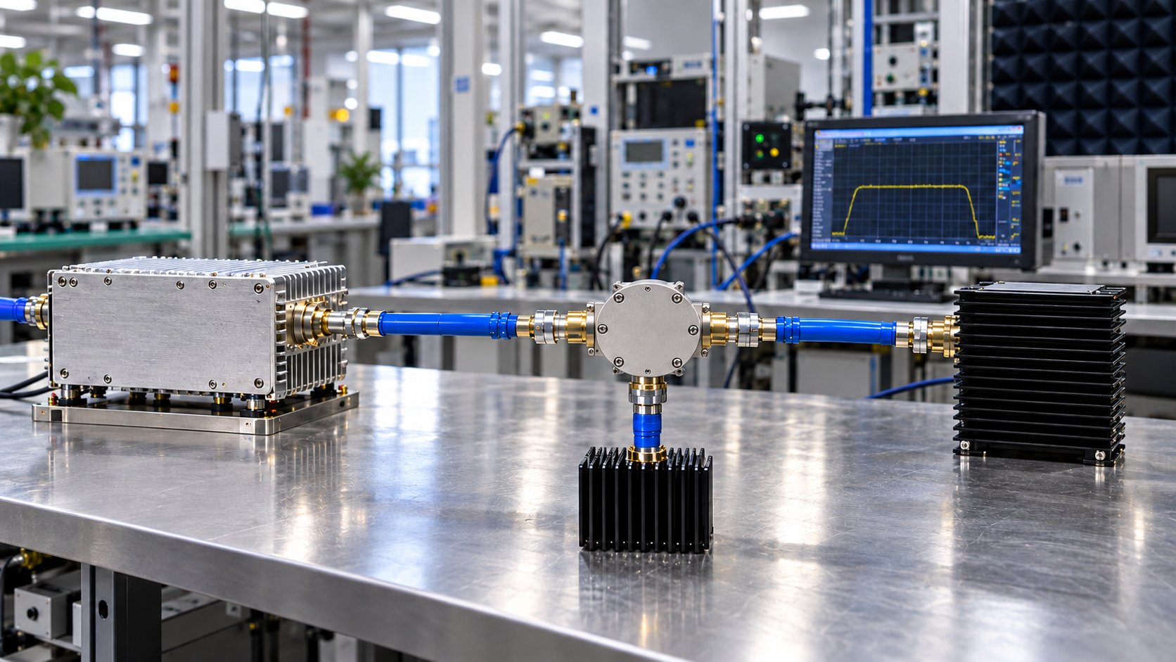
Not every C-UAS RF PA chain needs an isolator or circulator.
Add an RF isolator or circulator when the project needs a controlled reverse-power path or reduced PA exposure to reflections caused by downstream load changes that the existing PA and RF chain have not been shown to handle under the required operating conditions.
An isolator or circulator does not correct a mismatched antenna. It changes the path taken by reflected RF energy, allowing that energy to be diverted toward a defined termination instead of returning directly toward the PA.
The added device also consumes system margin through insertion loss, thermal dissipation, bandwidth limits, power-handling limits, and another RF interface that must be qualified.
Start with the reverse-power condition the project needs to control.
1. What Problem Does an Isolator or Circulator Solve in the RF PA Chain?
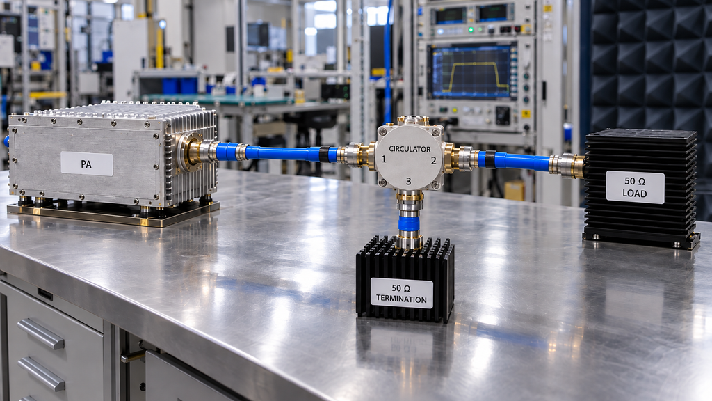
During normal operation, RF power leaves the PA and travels through the downstream chain toward the load.
When the load is mismatched, some of that power returns toward the source. Its magnitude and phase depend on the installed path, which may include switches, filters, couplers, combiners, feeders, connectors, and antennas.
Without added isolation, part of the reflected energy can reach the PA output.
A three-port circulator routes forward power from one port to the next and sends returning energy toward the third port. When the circulator is used for PA isolation, that third port needs a termination rated for the defined reverse-power event.
A two-port isolator integrates that termination into the assembly.
The antenna or load remains mismatched after the device is installed. What changes is the reverse-energy path and the amount of reflected energy coupled back toward the PA.
Before selecting hardware, define:
- where reflected energy can originate;
- which reflections can reach the PA; and
- where the reverse energy should be dissipated under the required worst-case condition.
If those points are unknown, there is not enough information to select the isolation architecture.
2. When Is an Isolator or Circulator Actually Needed?
Additional isolation becomes more relevant when the expected reflected-power condition falls outside the demonstrated coverage of the existing PA qualification, protection behavior, or installed load control.
PA output power alone is not enough to make the decision.
Conditions That Strengthen the Case for Isolation
An isolator or circulator deserves closer consideration when the downstream load can change substantially during operation.
Examples include antenna disconnection, RF switching transitions, uncertain field antenna conditions, changing feeder paths, or configurations in which the PA may temporarily see a reflection condition outside its normal matched-load state.
Isolation is also useful when the architecture needs a defined destination for reflected energy rather than allowing that energy to return directly toward the PA.
A gap in mismatch evidence is another reason to investigate. A PA may have documented protection functions without having qualification evidence for every reflection magnitude, phase, duration, frequency, power level, and thermal state the C-UAS system may encounter.
If that missing qualification is blocking the architecture decision, verify the RF PA mismatch qualification under real C-UAS conditions.
Conditions Where an Added Device May Not Be Justified
Additional isolation may add little value when the load environment is tightly controlled and the PA already has qualification evidence covering the required mismatch envelope under the relevant operating conditions.
The added component also costs RF and thermal margin.
Insertion loss reduces downstream RF power. Limited bandwidth can prevent one device from covering all C-UAS operating windows. The termination may not support the required reflected-power event, and every added component brings more size, connectors, thermal interfaces, and qualification work.
Use additional isolation when the reduction in reverse-power risk justifies those penalties.
3. Isolator or Circulator: Which Reverse-Power Architecture Fits the Chain?
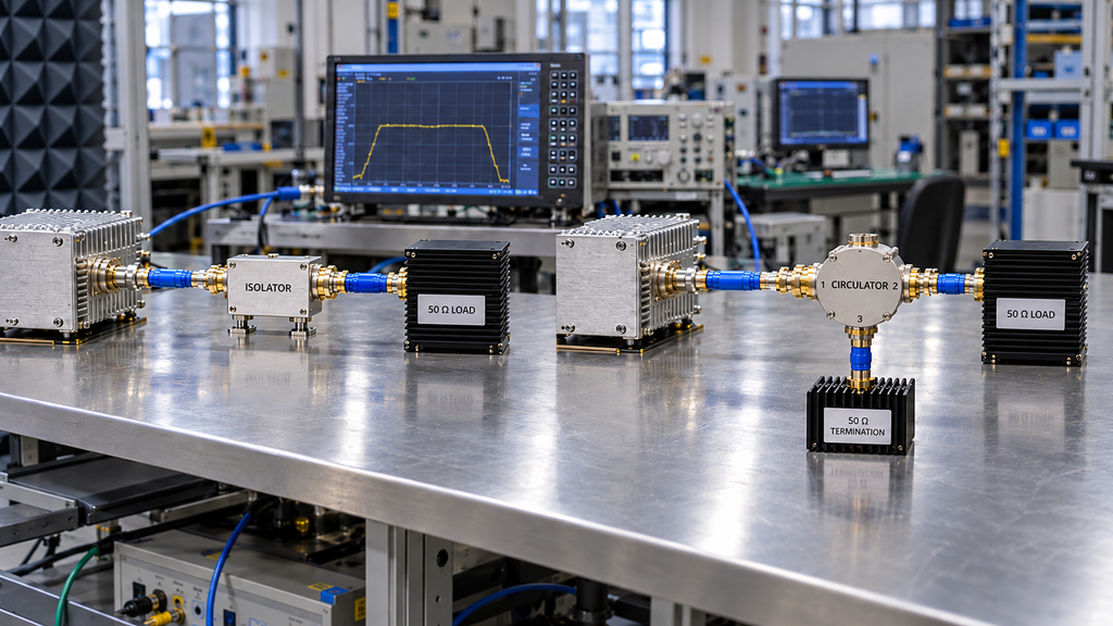
Once additional isolation is justified, choose the architecture around the reverse-energy condition and termination requirement.
When a Two-Port Isolator Is the Simpler Route
A two-port isolator works well when the system needs a compact series element and its integrated termination can handle the expected reflected-power condition.
Integration is simpler because there is no separate third-port load to mount and cool.
The engineer still needs to verify:
- operating frequency and bandwidth;
- insertion loss;
- isolation across the required range;
- forward-power rating under the relevant waveform and duty condition;
- reverse-power or termination capability;
- thermal path;
- connector and mechanical constraints.
If the integrated termination becomes the limiting element during the required reflection event, the compact package no longer solves the full design problem.
When a Circulator With an External Load Gives Better Control
A circulator with an external third-port load separates RF routing from the termination.
That is useful when the project needs a larger or independently cooled load, wants access to the reflected-power path for monitoring, or needs more flexibility in how reverse energy is handled mechanically and thermally.
The circulator and load can then be evaluated as separate parts of one architecture.
The trade-off is more size, interfaces, mounting, cabling or connector requirements, and integration work.
Choose the architecture whose RF path, termination capability, and thermal design cover the defined reverse-power event.
RF PA Isolation Architecture Decision Matrix
RF PA Isolation Architecture Decision Matrix
Compare all three routes and the evidence each decision needs · Swipe horizontally →
| Decision Factor | No Added Device | Isolator | Circulator + External Load | Required Evidence |
|---|---|---|---|---|
| Frequency / bandwidth | Existing PA qualification and RF-chain load behavior must remain acceptable across the required operating windows | Device must cover every required operating window with acceptable RF performance | Circulator and external load arrangement must cover the required operating windows | PA operating range, RF-chain frequency plan, component specifications |
| Expected mismatch | Existing PA qualification must cover the defined mismatch environment | Added isolation must address the reflection condition that remains unresolved | Architecture must route the defined reflection condition to the third-port load | Project mismatch envelope, antenna / feeder conditions, PA qualification |
| Forward power | No added passive-device loss, but the PA must tolerate the required load environment | Isolator must support the defined forward-power condition | Circulator must support the defined forward-power condition | Pout definition, waveform, duty cycle, operating state |
| Reverse power | PA must already be qualified for the required reflected-power condition | Internal termination must handle the required reverse-energy event for the defined duration / duty condition | External load must handle the required reverse-energy event for the defined duration / duty condition | Reflected-power requirement, event duration, duty condition, applicable qualification |
| Insertion loss | No isolation-device loss added | Loss must fit the RF power budget | Loss must fit the RF power budget | Component loss specification under required conditions |
| Required isolation | Relies on PA and existing RF-path behavior | Isolation must be sufficient across the required band and conditions | Circulator isolation and third-port termination must meet the required boundary | Isolation specification, frequency and temperature conditions |
| Termination capacity | No separate isolation termination | Internal termination capability must be sufficient | External termination can be selected and cooled separately | Termination power and thermal specifications |
| Thermal dissipation | No heat from an added isolation device | Dissipative forward loss and absorbed reverse energy add to the device thermal load | Circulator dissipation and external-load dissipation both require thermal paths | Loss, reflected-power condition, cooling design |
| Placement | PA qualification must cover reflections from all relevant downstream sources | Device must sit upstream of the reflection sources it is intended to isolate | Circulator must be positioned so the required reflected path reaches the third port | Complete RF-chain topology |
| PA protection | Existing protection and qualification carry the full burden | PA protection remains relevant even with added isolation | PA protection remains relevant even with a circulator | Protection behavior and mismatch qualification |
| Acceptance evidence | Must prove the PA and installed RF path cover the required conditions | Must prove the PA plus isolator architecture covers the required conditions | Must prove the PA, circulator, termination, and placement cover the required conditions | Approved test conditions, reference plane, FWD / REV / VSWR records |
4. Where Should It Sit in a Multi-Band C-UAS RF Chain?
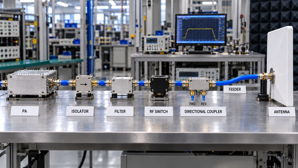
Placement determines which reflections the device can isolate.
“Install an isolator after the PA” is too vague for a multi-band RF system.
Consider this path:
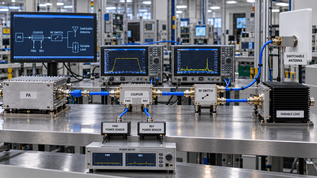
PA → filter → RF switch → coupler → feeder → antenna
An isolator directly after the PA places every downstream component behind the isolation point. That may be appropriate when the goal is to reduce PA exposure to reflections originating anywhere farther down the path.
Move the isolator to the antenna side of the RF switch and the protection scope changes. Reflections originating upstream of that position are no longer behind the isolator.
In RF amplifier system integration, multi-branch systems add more cases. One PA may feed several switched antennas, or multiple PA branches may converge through switching or combining networks. One isolator may not cover every reflection source or operating window.
Filters matter as well. Their impedance outside the intended passband and their behavior during switching can change the load presented toward the PA.
For each proposed position, identify:
- which downstream components can generate or transform a reflection;
- which reflections are isolated from the PA;
- whether every required frequency window passes through the device;
- where reflected energy is terminated; and
- where FWD, REV, or VSWR is measured.
After fixing the isolation position, verify the resulting feeder and antenna load conditions using the same assumptions that supported the architecture decision.
There is no single placement diagram for every C-UAS system. The actual switching, filtering, combining, feeder, and antenna architecture determines the position.
5. What Are the Insertion-Loss, Bandwidth, Power, and Thermal Trade-Offs?
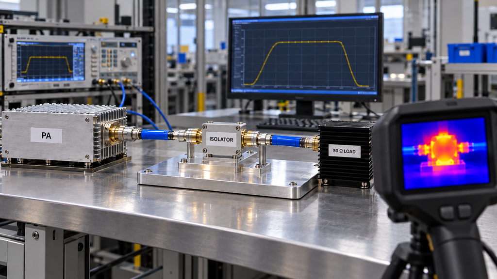
An isolator or circulator only helps if the RF chain still meets its requirements after the device is added.
Insertion loss reduces downstream RF power. The dissipative part of that loss becomes heat in the device and belongs in the thermal budget.
Check loss and isolation across the required operating range, not only at a convenient center frequency. A component that performs well in one C-UAS frequency window may not provide the same result in another.
Forward-power and termination ratings answer different questions. The forward rating limits transmitted RF under the specified waveform and duty condition. The termination rating limits the reverse-energy event the load can absorb.
Thermal design connects both limits.
In an isolator, forward dissipation and absorbed reflected energy can load the integrated termination and device body. In a circulator architecture, the external termination can have its own thermal path, while the circulator still has internal dissipation and operating limits.
Before approving the architecture, confirm that:
- every required frequency window is covered;
- insertion loss fits the RF power budget;
- isolation is adequate under the defined conditions;
- forward-power capability covers the waveform and duty cycle;
- the termination can absorb the specified reverse-power event; and
- the thermal path can remove the resulting dissipation.
A “200 W” component label does not establish those conditions.
6. Can PA VSWR Protection Replace an Isolator or Circulator?
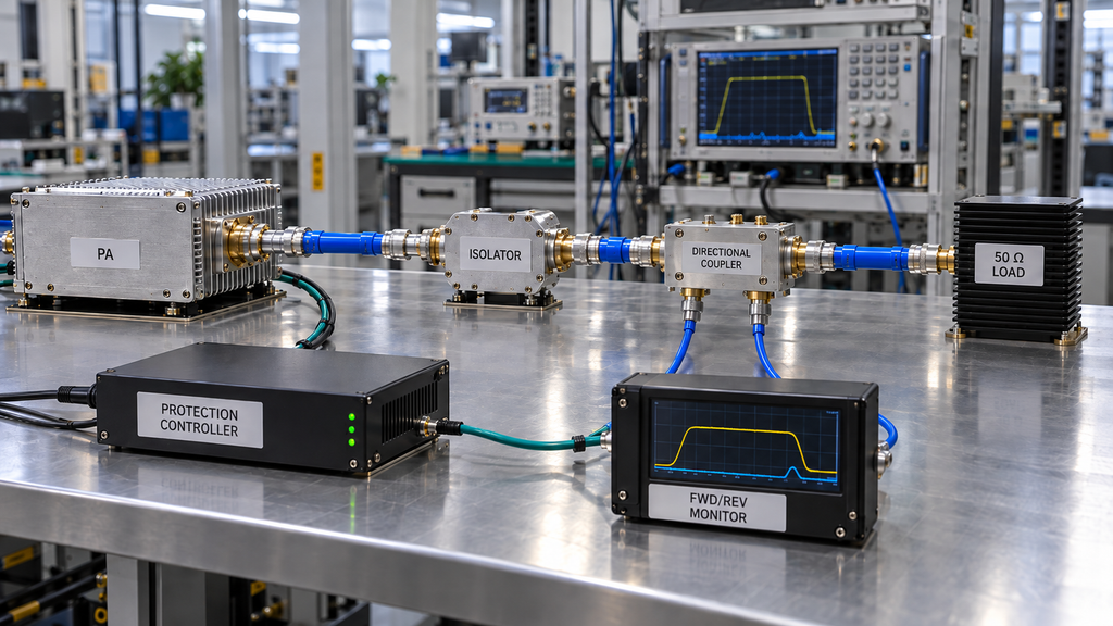
RF power amplifier load mismatch protection and RF isolation act at different points in the problem.
A PA protection system can detect abnormal forward or reflected conditions and respond with an alarm, power reduction, shutdown, or another defined action.
An isolator or circulator changes how reverse RF energy propagates before that protection response occurs.
Both may be needed in the same design.
Existing PA qualification can reduce the need for added isolation when it covers the actual project mismatch envelope, operating state, duration, thermal condition, and reference plane. A specification that only says “VSWR protection” does not establish that coverage.
If the qualification boundary is incomplete, the evidence is not yet sufficient to say that the PA architecture can replace added isolation. That is an evidence gap, not a product failure.
Adding an isolator also does not remove the need for PA protection. Abnormal conditions can still require sensing, foldback, shutdown, or recovery behavior.
The design needs both a defined reverse-energy path and a defined PA protection response.
If the system is already installed and the issue has become an active reflected-power alarm, continue with reflected-power alarm diagnosis after C-UAS installation.
What Should the RFQ and Acceptance Test Define?
“Need a 200 W isolator” is not a complete RFQ.
Define the operating conditions first:
- frequency or frequency windows;
- forward-power definition and waveform / duty condition;
- normal load condition;
- worst required mismatch or reflected-power event;
- intended isolator / circulator position;
- allowable insertion-loss budget;
- required isolation;
- reverse-power / termination requirement;
- internal or external termination architecture;
- cooling and thermal condition;
- operating-temperature requirement;
- connector and mechanical constraints;
- PA protection / mismatch qualification;
- acceptance reference plane;
- required evidence for RF power amplifier output VSWR, FWD, and REV;
- test duration where relevant.
These inputs give the supplier or integrator a testable engineering requirement instead of a single wattage target.
The acceptance record should use the same boundaries. It should show why isolation is or is not required, where reverse energy is terminated, whether the RF and thermal budgets remain valid, and what evidence supports the conclusion.
RF SKYPOWER can review the PA-side and RF-chain requirements when the project provides operating frequencies, PA power, waveform or duty condition, load / mismatch envelope, intended RF topology, protection evidence, and thermal requirements. A third-party isolator or circulator still needs its own formal specifications and project-level acceptance evidence.
Conclusion
Use an isolator or circulator when the C-UAS RF PA chain needs a controlled reverse-power path or reduced PA exposure to reflected energy that the existing PA qualification and installed RF path have not been shown to handle.
Frequency coverage, forward power, expected mismatch, PA qualification, insertion loss, isolation, termination capability, thermal state, and placement determine whether the right architecture is a two-port isolator, a circulator with an external load, or no added isolation.
Complete the RF PA Isolation Architecture Decision Matrix with the actual RF-chain topology before selecting hardware. If the existing PA qualification and controlled load path already cover the required mismatch environment, extra isolation may add cost and loss without solving a real risk. If a reverse-power risk remains, define where that energy must be routed and dissipated before choosing the component.
For RF SKYPOWER engineering review, provide the operating frequencies, PA output condition, waveform or duty cycle, required load / mismatch envelope, RF-chain topology, protection or qualification evidence, and thermal requirements. Once the isolation architecture is defined, the RF Power Amplifier Modules product family can be reviewed against the resulting PA requirements.