










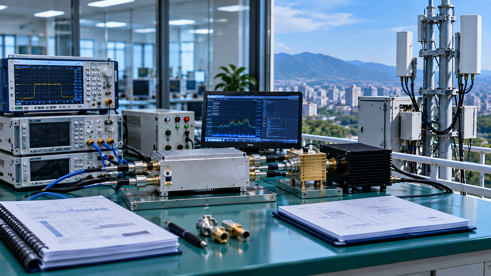
RF PA mismatch qualification does not automatically cover every real C-UAS antenna condition. It supports the field application only when the real operating condition sits inside the tested qualification boundary, or when the differences can be shown not to affect the claim being made.
That is why a field reading of 3:1 VSWR is not automatically less demanding than a laboratory qualification at 5:1. The PA stress can also depend on frequency, RF operating point, waveform, Vdc, mismatch phase, exposure duration, thermal state, protection configuration, and the reference plane used for the mismatch.
The first task is to find out what the original qualification actually proved.
For example, a C-UAS integrator may receive a PA report showing 5:1 VSWR protection on the bench. Later, the installed system shows only a 3:1 antenna-side alarm, so the team assumes the field condition is covered. That conclusion may still be unsafe if the bench test used a PA-port reference plane, short exposure, room-temperature start, and one frequency point, while the field alarm comes after a long feeder path during hot rooftop operation. The question is not whether 3:1 is lower than 5:1. The question is whether both conditions describe the same stress at the PA.
1. What Does the Existing Load-Mismatch Qualification Actually Prove?
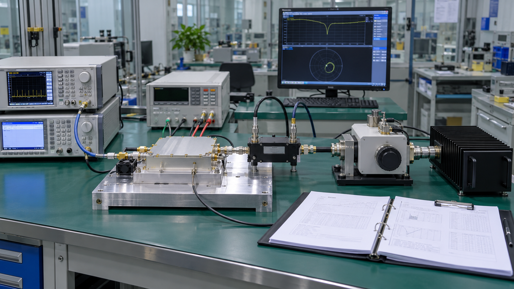
A useful RF amplifier mismatch qualification report should define a qualification boundary: the exact conditions under which the mismatch claim was demonstrated.
Start with the claim. A report may show that protection triggers correctly, that the PA survives a defined mismatch event, that it recovers afterward, or that it maintains specified performance while mismatched. These are different claims.
A statement such as qualified to 5:1 VSWR is incomplete unless the report also states what was qualified and under what conditions.
A weak report may say “5:1 VSWR tested” but omit whether the test checked survival, output stability, reflected-power alarm accuracy, shutdown timing, or recovery after mismatch removal. Those are not the same result. A PA that survives a short mismatch event may still reduce output, trigger early protection, or fail to recover cleanly in a hot continuous-duty cabinet.
Extract at least:
- test frequency or frequency range;
- RF operating point;
- waveform and duty cycle;
- module-side Vdc;
- mismatch magnitude;
- mismatch phase or impedance region, when relevant;
- measurement reference plane;
- exposure duration;
- event count or repetition;
- cold or hot thermal state;
- protection and recovery behavior;
- hardware revision;
- firmware or threshold revision.
The useful engineering statement is not:
Qualified to 5:1 VSWR.
It is:
Qualified for this mismatch claim under these operating and configuration conditions.
The same maximum VSWR can create different electrical or thermal stress when the surrounding conditions change.
If the report does not identify the claim type, reference plane, operating point, or applicable hardware and firmware configuration, do not fill in the missing scope by assumption. The evidence stops where the report stops.
If new qualification evidence must be generated, that work belongs to load-mismatch qualification testing, not to this applicability review.
2. How Should the Real C-UAS Antenna Mismatch Condition Be Defined?
Define the RF PA field mismatch condition with the same discipline used for the bench qualification. A dashboard alarm or one VSWR reading is not enough to define the load condition seen by the PA.
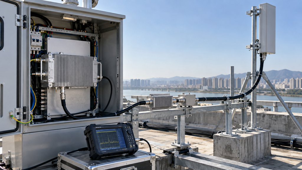
At minimum, record:
- operating frequency;
- RF output operating point;
- waveform and duty cycle;
- module-side Vdc;
- PA-interface mismatch condition;
- measurement reference plane;
- exposure duration;
- repeat rate;
- thermal state;
- installed RF path;
- protection state;
- hardware and firmware identity.
The reference plane matters. Antenna-terminal VSWR, feeder-input VSWR, PA-port VSWR, and a controller alarm are not interchangeable measurements.
A typical mistake is comparing a rooftop antenna VSWR reading with a bench PA-port mismatch test. Between those two points, the system may include feeder cable, filters, switches, couplers, connectors, and lightning-protection hardware. These parts can reduce, rotate, or reshape the reflection seen by the PA. A 3:1 antenna-side reading does not automatically mean the PA output port experienced the same 3:1 condition.
A C-UAS installation may place feeders, filters, switches, combiners, couplers, connectors, or other RF components between the PA and the measurement point. Those parts can change both the magnitude and phase of the reflection presented back to the PA.
If the field measurement is not taken at the PA interface, establish a defensible relationship between that measurement and the actual PA-port condition. That may require known RF-path characteristics or calibrated measurements. Assumed path values are weak evidence.
The output should be a field mismatch condition that can be compared with the laboratory qualification boundary, not just a note that says field VSWR = 3:1.
For the normal installation boundary, use the broader RF PA load conditions before integration framework. If the task has already shifted from qualification applicability to diagnosing an installed alarm, treat it as a separate reflected power alarm troubleshooting problem.
3. How Do You Normalize Bench and Field Conditions Before Comparing Them?

A bench vs field VSWR qualification review should compare both sides only after they are expressed in the same engineering framework.
The key variables usually include:
- frequency;
- waveform and duty cycle;
- RF operating point;
- Pin and Pout definitions;
- Vdc;
- reference plane;
- mismatch magnitude;
- phase or impedance region;
- exposure duration;
- repetition;
- thermal state;
- protection configuration;
- hardware revision;
- firmware or threshold revision.
Not every difference carries the same weight.
A difference is decision-critical when it could change whether the existing qualification supports the required field claim. Examples include a different reference plane, an uncovered frequency, a short cold qualification being applied to hot continuous operation, or phase coverage that does not represent the field condition.
Other differences can be recorded without changing the applicability decision, but only when there is a technical basis for treating them as non-decisive.
There is no universal formula that turns frequency, phase, waveform, operating point, thermal state, and reference-plane differences into one equivalent VSWR number. If a decision-critical condition cannot be aligned or explained, the comparison should stop short of full coverage.
A practical comparison may look like this: the bench report shows 5:1 VSWR at the PA output port, 2.4 GHz, room-temperature start, short exposure, and a defined protection-recovery check. The field case shows a 3:1 alarm measured near the antenna, after feeder and filter loss, during hot-state operation after 40 minutes. In this situation, the lower VSWR number helps, but it does not close the reference-plane and thermal-state gaps. The correct status is Partially Covered, not automatically Covered.
Bench-to-Field Mismatch Coverage Matrix
Bench-to-Field Mismatch Coverage Matrix
Align each condition before assigning coverage · Swipe horizontally →
| Condition | Bench Qualification | Real C-UAS Condition | Comparable? | Inside Qualified Envelope? | Evidence Gap | Decision |
|---|---|---|---|---|---|---|
| Qualification claim | Record whether the bench claim covers survivability, protection, recovery, maintained performance, or another defined result | Record the field claim that must be supported | Compare only if both sides require the same engineering claim | Confirm only when the bench claim supports the required field claim | Identify any difference in claim scope | CoveredPartially CoveredNot Demonstrated |
| Frequency | Record tested frequency or range | Record actual operating frequency or range | Compare where frequency coverage overlaps | Confirm whether the field range falls within tested coverage | Note uncovered frequencies | CoveredPartially CoveredNot Demonstrated |
| Waveform / duty | Record waveform and duty-cycle conditions | Record field waveform and duty cycle | Check whether waveform-related stress is comparable | Confirm only where the tested condition supports the field condition | Note untested waveform or duty difference | CoveredPartially CoveredNot Demonstrated |
| Operating point | Record RF operating point used in qualification | Record actual project operating point | Compare the relevant power condition | Confirm whether the field operating point lies within supported conditions | Note any unverified power difference | CoveredPartially CoveredNot Demonstrated |
| Pin / Pout definition | Record how input and output power were defined | Record field definitions at the relevant planes | Align definitions before comparing values | Confirm only after definitions match | Identify definition or reference-plane mismatch | CoveredPartially CoveredNot Demonstrated |
| Vdc | Record qualification supply condition | Record actual module-side Vdc | Compare the supply condition relevant to stress and protection | Confirm whether the field condition is supported | Note unsupported supply differences | CoveredPartially CoveredNot Demonstrated |
| Reference plane | Record where mismatch was defined or measured | Record where field mismatch is defined or measured | Comparable only when planes match or can be defensibly related | Confirm after the PA-port condition is established | Identify unresolved path conversion | CoveredPartially CoveredNot Demonstrated |
| Mismatch magnitude | Record tested VSWR, reflection coefficient, or impedance condition | Record field mismatch magnitude at the relevant plane | Compare only with surrounding conditions aligned | Confirm whether the field magnitude lies within demonstrated scope | Note unsupported mismatch level | CoveredPartially CoveredNot Demonstrated |
| Phase / impedance region | Record phase coverage or impedance region where available | Record the relevant field phase or impedance region where needed | Check whether the tested region represents the required condition | Confirm only where the claim supports the relevant region | Identify missing phase or impedance evidence | CoveredPartially CoveredNot Demonstrated |
| Exposure duration | Record mismatch exposure time | Record expected field event duration | Compare the time scale of the stress | Confirm whether field duration is within supported evidence | Note longer or undefined exposure | CoveredPartially CoveredNot Demonstrated |
| Repetition | Record number or rate of mismatch events | Record expected repeat behavior | Compare single-event and repeated-event exposure | Confirm whether repetition is covered | Note repeated-event evidence gap | CoveredPartially CoveredNot Demonstrated |
| Thermal state | Record cold, stabilized, or other defined thermal state | Record actual field thermal condition | Compare only where thermal state is represented | Confirm whether the required thermal condition is supported | Note cold-to-hot evidence gap | CoveredPartially CoveredNot Demonstrated |
| Protection configuration | Record enabled protection and relevant settings | Record field protection configuration | Confirm the same protection logic applies | Confirm only when relevant protection behavior is represented | Note configuration differences | CoveredPartially CoveredNot Demonstrated |
| Hardware revision | Record qualified hardware revision or scope | Record installed hardware revision | Review qualification applicability across revisions | Confirm only where applicability is documented or technically justified | Identify unreviewed hardware changes | CoveredPartially CoveredNot Demonstrated |
| Firmware / threshold revision | Record qualified firmware or threshold configuration | Record installed firmware or threshold configuration | Review whether sensing, thresholds, protection, or recovery could change | Confirm only where the revision remains within supported scope | Identify firmware or threshold evidence gap | CoveredPartially CoveredNot Demonstrated |
This matrix is a comparison framework. It does not replace the qualification report or field evidence. Real values must come from the project.
4. When Is the Field Condition Inside the Qualified Envelope?
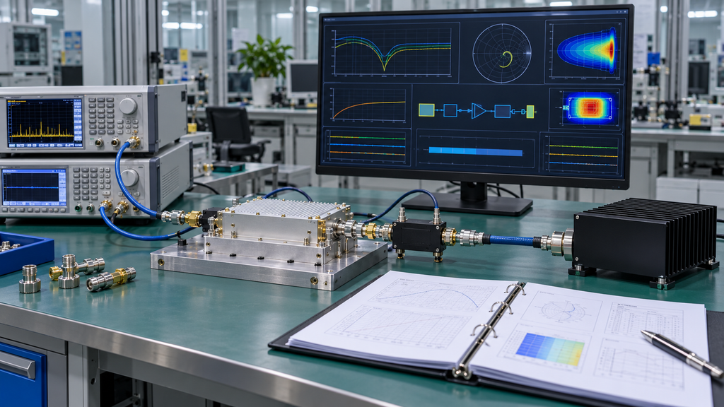
The result should land in one of three engineering states.
Covered
Use Covered only when the decision-critical field conditions sit inside the demonstrated qualification boundary, or when the differences are supported by evidence showing that they do not change the required claim.
A lower field VSWR can support that conclusion. It cannot prove it alone.
Partially Covered
Use Partially Covered when the existing report supports an important part of the field condition but at least one material difference remains unresolved.
For example, frequency, operating point, and mismatch magnitude may be covered while the field application introduces a hotter thermal state or an unverified phase region.
That is useful evidence. It is not full applicability.
Not Demonstrated
Use Not Demonstrated when the available evidence cannot reliably map the field condition into the qualified boundary.
Typical reasons include:
- reference planes cannot be reconciled;
- the operating point is unclear;
- phase information needed for the claim is missing;
- the qualification was cold-state only while the project requires hot-state evidence;
- a hardware or firmware change may affect sensing or protection;
- the report does not establish the required claim type.
Not Demonstrated is an evidence conclusion, not a product failure.
It means the qualification evidence stops before the project claim can be made.
5. What Evidence Gap Actually Requires Additional Mismatch Testing?
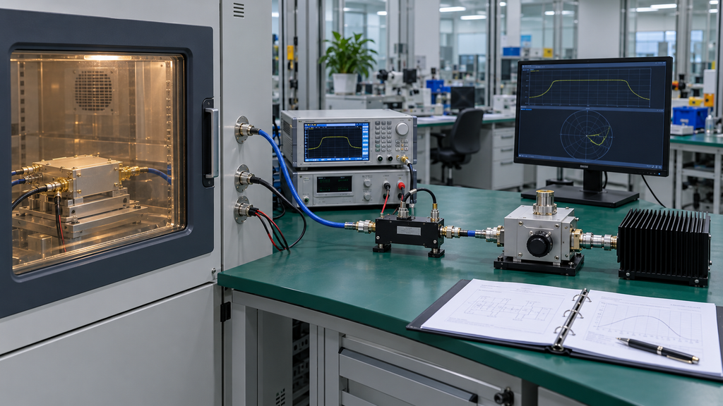
Not every difference between a qualification report and a field installation justifies repeating the entire mismatch qualification.
For example, if the field project uses the same PA revision, same firmware threshold, same frequency range, same waveform, same PA-port mismatch boundary, and same hot-state duration, but only updates a documented cable-loss correction, a full mismatch requalification may not be necessary. A controlled applicability note or report addendum may be enough. The missing item should drive the evidence request, not fear of mismatch itself.
Ask this first:
Could the missing evidence change the claim the project needs to make?
If no, record the difference and document why it does not affect applicability.
If yes, or possibly yes, define the missing evidence precisely.
A gap may justify additional verification when it could change:
- survivability;
- protection behavior;
- recovery behavior;
- maintained performance during mismatch.
The request should identify the unresolved condition instead of saying retest VSWR.
The missing evidence might be:
- one uncovered frequency range;
- a higher RF operating point;
- a different waveform or duty cycle;
- hot-state operation;
- longer exposure;
- repeated mismatch events;
- an untested phase or impedance region;
- a revised hardware or firmware configuration.
The goal is to close the decision-critical gap, not repeat high-stress testing for conditions already supported.
If the gap requires a load mismatch RF amplifier test, carry only the unresolved condition into the existing qualification procedure.
Until the missing condition is resolved, keep the result at Partially Covered or Not Demonstrated. Do not stretch the old report beyond its evidence.
6. What Changes Should Trigger Requalification?
Mismatch qualification should remain manageable across the product lifecycle. It should not be treated as permanently transferable to every later configuration.
Changes worth reviewing include:
- output-stage hardware;
- coupler or detector design;
- protection circuitry;
- firmware or protection thresholds;
- supply range;
- target output power;
- operating frequency band;
- waveform or duty cycle;
- cooling architecture;
- the mismatch claim itself;
- duration or thermal-state requirements.
Start with a change-impact review, not automatic full requalification.
A label change or non-functional packaging change should not trigger the same review as a new coupler design, changed reflected-power detector, revised shutdown threshold, or different final-stage device. The first type may only need documentation. The second type can change how mismatch is sensed, limited, or survived, so it may require focused verification.
Ask whether the change could alter mismatch stress, sensing, protection behavior, recovery, or the operating boundary behind the original claim.
If it cannot, the existing evidence may remain applicable with documented technical justification.
If it can, identify the affected part of the qualification boundary and verify only what must be re-established.
A revision number alone does not prove that the old qualification is invalid. It also does not prove that the old report still applies. The technical relationship between the change and the original claim is what matters.
Where that relationship is unclear, do not silently extend the qualification to the new configuration.
What Should the RFQ and Acceptance File Require?
An RFQ that asks only for a 5:1 VSWR protection report leaves too much ambiguity for later project use.
The qualification evidence should identify:
- required mismatch claim;
- qualification scope;
- frequency coverage;
- RF operating point;
- waveform and duty cycle;
- Vdc;
- reference plane;
- mismatch magnitude;
- phase coverage where relevant;
- exposure duration and repetition;
- thermal state;
- protection and recovery behavior;
- hardware and firmware applicability;
- evidence level;
- requalification triggers;
- the process for handling field conditions outside the original envelope.
The goal is not just to receive a qualification report. The goal is to receive a report whose applicability can still be judged when a later project uses a different frequency, RF path, operating point, waveform, thermal state, or revision.
RF SKYPOWER can review an existing mismatch report together with the actual C-UAS field conditions and classify the available evidence as Covered, Partially Covered, or Not Demonstrated. Once that evidence boundary is clear, the project can move into a specific RF PA module discussion without treating product availability as proof of field-condition coverage.
Qualification Status and Next Route
Use the evidence boundary to choose the next step
| Qualification Status | What It Means | Recommended Next Step | Route |
|---|---|---|---|
| Covered | The decision-critical field conditions are supported by the existing qualification evidence. | Confirm the project configuration and move into product / RFQ review. | RF PA modules → |
| Partially Covered | The existing report supports part of the field condition, but a material evidence gap remains. | Review the missing frequency, operating point, phase, thermal state, duration, or revision before extending the qualification claim. | Engineering review / RFQ → |
| Not Demonstrated | The available evidence cannot yet support the required field-condition claim. | Define the exact missing evidence or additional mismatch verification required before product-level acceptance. | Engineering review / RFQ → |
For an engineering evidence review, provide the existing mismatch qualification report, actual C-UAS field conditions, reference plane, hardware / firmware revision, and the identified evidence gap.
RFQ and Engineering Takeaway
Bench load-mismatch qualification supports a real C-UAS project only when the field condition lies inside the demonstrated qualification boundary, or when the important differences are supported by evidence showing that they do not change the required claim. A lower field VSWR does not prove coverage by itself.
Complete the Bench-to-Field Mismatch Coverage Matrix before deciding whether the existing report is enough. If a decision-critical gap remains, define the missing condition precisely and request only the evidence needed to close it. Not Demonstrated means the evidence stops there. It does not mean the PA has failed.
For an RF SKYPOWER engineering evidence review or RFQ, provide the existing mismatch qualification report, target frequency, RF operating point, waveform or duty cycle, module-side Vdc, field mismatch condition, reference plane, available VSWR or reflection evidence, duration and repetition, thermal state, protection requirements, hardware and firmware revisions, evidence level, and any required requalification trigger. These inputs define the review scope; they do not create project-level coverage until the qualification evidence and field conditions have been compared.