










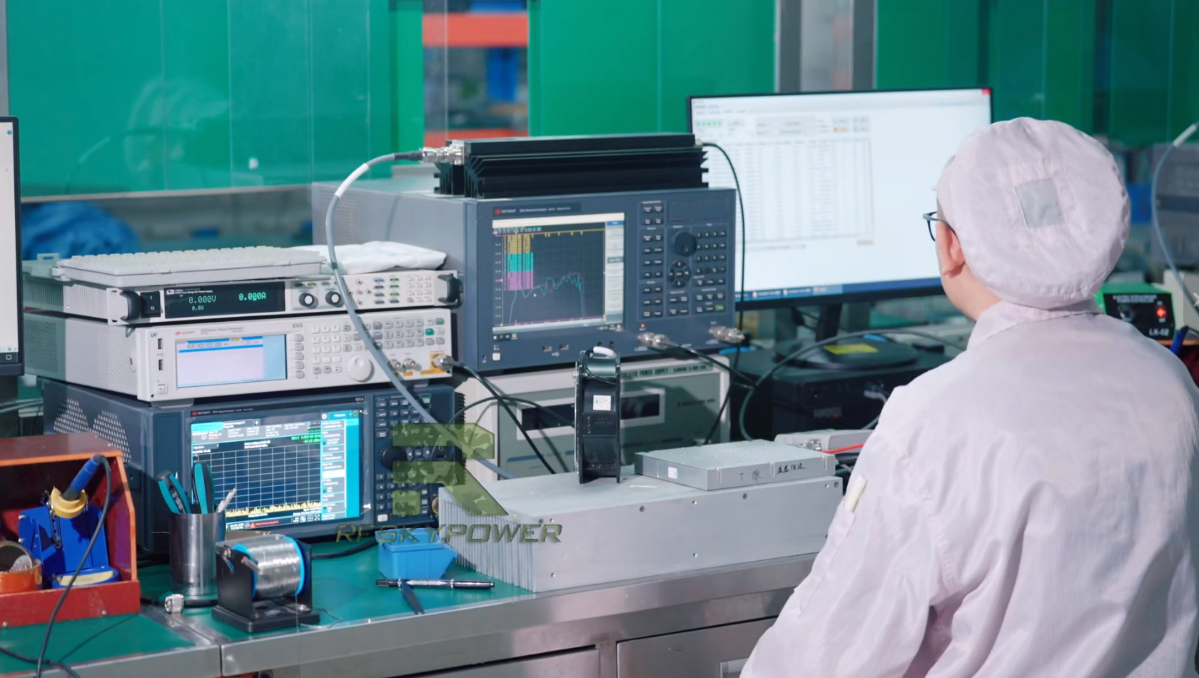
A dummy load rating for RF amplifier acceptance cannot be judged from a 50 Ω label or a large wattage number alone. The load must handle the RF power that reaches its input at the required frequency, operating mode, duty cycle, duration, cooling condition, mismatch limit, and connector interface.
Start with the load-input demand rather than the PA nameplate alone. Compare each required condition with the manufacturer rating for the exact load. Treat continuous or average power and peak power as separate capabilities when the waveform requires both. A short-duration rating is not a continuous full-power rating.
There is no universal 1.5× or 2× dummy-load power rule. A project may choose additional margin, but that margin cannot replace frequency coverage, peak-power capability, cooling, test duration, VSWR, or formal equipment data.
Where the manufacturer rating and planned setup cannot be aligned on a critical condition, hold the test rather than treating the load as a qualified RF reference.
1. What Does a Dummy Load Rating Need to Prove for RF PA Acceptance?
A 50 ohm dummy load for an RF power amplifier test must absorb the required RF energy while remaining within its approved electrical, RF, thermal, and mechanical operating limits.
A wattage label needs operating conditions
A power rating condition is the set of manufacturer-defined conditions under which a stated load capability is valid. Depending on the load, those conditions may include frequency range, cooling method, ambient temperature, coolant conditions, installation, duty cycle, pulse limits, operating duration, or other thermal constraints.
A wattage value without that context is incomplete evidence.
For RF PA acceptance, the qualification boundary should cover:
- nominal impedance;
- applicable frequency range;
- continuous or average power capability;
- peak capability when relevant;
- duty-cycle and pulse limits when applicable;
- permissible operating duration;
- cooling method;
- environmental or cooling-medium conditions;
- specified VSWR or return-loss behavior;
- connector or flange interface;
- manufacturer installation conditions that affect the rating.
Nominal 50 Ω defines an impedance target. It does not prove acceptable matching across every required frequency, power level, and thermal state. Likewise, a sufficient-looking wattage does not prove that the same capacity remains available under the actual cooling arrangement.
The practical question is:
Does this specific load remain within its approved rating envelope for the actual RF power, operating mode, frequency range, duration, cooling condition, mismatch requirement, and interface used in this test?
Two loads are only partially comparable until those conditions are aligned. A higher nameplate wattage does not automatically make one load more suitable if its usable rating depends on different cooling, duration, frequency, or environmental conditions.
Before proceeding, define the minimum dummy-load qualification boundary for the planned acceptance test. If the formal rating conditions are unavailable, or the actual PA test conditions are still unknown, the fixture is not ready for approval.
Once the load passes qualification, keep the controlled-load result separate from any conclusion about the installed RF path.
2. How Do RF Power, Duty Cycle, and Test Duration Set the Required Load Rating?
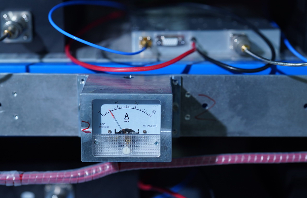
Set the RF dummy load power rating from the RF power that actually enters the load rather than from the PA nameplate alone.
The reference plane is the defined point in the RF path at which power, mismatch, or another RF quantity is evaluated. For dummy-load qualification, the relevant power requirement should correspond to the load-input reference plane. Cables, couplers, adapters, or other components may separate the PA output from the load input, so those two planes should not be treated as identical without evidence.
For continuous-wave or sustained full-power testing, compare the expected load-input power with the manufacturer’s applicable continuous rating under the specified cooling and environmental conditions. The planned test duration must also remain within the conditions attached to that capability.
Intermittent and pulsed operation need a separate comparison. Continuous or average power describes sustained or time-averaged thermal loading. Peak power describes the instantaneous or short-duration RF level the load must tolerate.
For a pulsed test, the qualification may need to align:
- average power at the load input;
- peak power;
- duty cycle;
- pulse width or other manufacturer-defined pulse limit;
- total test duration or dwell;
- cooling conditions attached to those ratings.
Do not turn a short rating into a continuous rating
A short-duration or peak rating cannot support prolonged continuous full-power acceptance by implication. A continuous rating also cannot prove that every required pulse or peak condition is acceptable.
A universal safety multiplier is unreliable because load designs attach different thermal, pulse, cooling, frequency, and installation conditions to their ratings. Applying the same 1.5× or 2× rule to every load can hide the parameter that actually controls suitability.
Match the conditions in this order:
defined load-input RF demand and waveform conditions → manufacturer rating under corresponding operating conditions → qualification decision
At minimum, align the reference plane, operating mode, continuous or average power, peak power when applicable, duty cycle, pulse condition when applicable, test duration, and cooling condition.
If the manufacturer documentation does not provide an applicable power capability for the intended operating mode, that load is not yet qualified for the full-power test.
The qualified load then becomes one controlled boundary within the broader full-power RF PA test, where swept-frequency, thermal-state, and Pin/Pout results are evaluated.
3. Why Do Cooling and Temperature Change the Usable Dummy Load Rating?
A high-power dummy load turns RF energy into heat. Its usable continuous capability depends on how effectively the setup removes that heat under the conditions associated with its rating.
Read the stated wattage together with the manufacturer’s thermal requirements. Depending on the load design, those conditions may include natural convection, forced airflow, liquid cooling, coolant temperature or flow, ambient temperature, mounting orientation, installation clearance, or other restrictions.
The stated continuous capability applies only while the required cooling conditions are maintained. Reduced airflow, incorrect liquid cooling, or operation outside the approved thermal conditions can change the usable rating.
Use the actual load’s own temperature-dependent limits or derating data. A curve or cooling requirement from another model cannot qualify this unit.
Record both cold and hot states
The thermal state describes the load after RF dissipation raises its temperature under the defined operating and cooling conditions. A cold starting condition does not represent prolonged high-power operation.
If the load moves outside its approved thermal boundary, its RF behavior may change. The fixture can then distort Pout, FWD/REV, VSWR, or protection results and make the source of the change harder to identify.
For each acceptance setup, record the actual cooling method, relevant ambient or coolant conditions, and intended operating duration as part of the load qualification.
Where required cooling cannot be verified, or the setup falls outside the manufacturer’s thermal conditions, the normal stated continuous power capability should not be used as the qualification basis.
4. What Frequency Range and VSWR Must the Dummy Load Meet?
Evaluate dummy load VSWR and power handling across every frequency used in the PA acceptance test. Check its specified VSWR or return loss across that full range.
A rise in load reflection changes the termination seen by the PA. It can affect reflected-power indications, the load condition presented to the PA, protection behavior, and some interpretations of measured output power.
A satisfactory center-frequency result is not a full-band guarantee. Nominal 50 Ω also does not prove that the load stays acceptably matched as power and temperature change.
Set the acceptable VSWR or return-loss boundary from the project requirement and the formal specification of the actual load. No single mismatch threshold applies to every RF PA acceptance setup.
When comparing two loads, preserve operating context. Their VSWR values are directly comparable only when frequency range, relevant power conditions, and applicable thermal conditions are sufficiently aligned.
Include the connector or flange
The RF interface can limit an otherwise suitable load. Verify that the connector or flange matches the required configuration and is suitable for the applicable operating condition.
A load whose internal RF performance is acceptable can still be unsuitable if the interface cannot support the required connection, power condition, or installation.
Incomplete frequency coverage, an unknown mismatch boundary, or an unverified interface is enough to keep the load from serving as the controlled reference until the gap is resolved.
A qualified dummy-load baseline still does not represent the installed antenna path, where cable loss, connectors, antenna mismatch, and other system effects must be considered separately in dummy load testing versus the real antenna path.
5. How Should the Dummy Load Be Separated From the Rest of the High-Power Test Path?
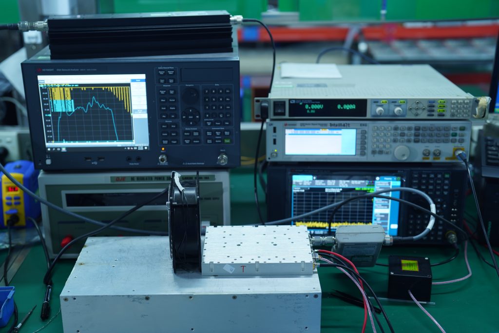
Qualifying the dummy load does not qualify the complete high-power RF test path.
The PA, directional coupler or sensor chain, high-power jumper, adapters, connectors, and dummy load each have separate operating boundaries. The first component to reach its limit caps the usable capability of the assembled path.
State the measurement reference plane. Record where Pout and the load-input condition apply, then identify the components between those points. Without those boundaries, the team may blame a cable or connector problem on the PA or dummy load.
Use the load documentation to qualify the load itself. Qualify the high-power jumper and connector assembly separately for the insertion loss, return loss, power capability, interface condition, and thermal behavior required by the test plan.
A qualified load cannot prove that its upstream jumper and connectors are also qualified.
The jumper and connector assembly needs its own dummy load cable qualification, because its S11, S21, power handling, connector condition, and thermal behavior are separate from the load rating.
An unclear reference plane or an unverified power or mismatch limit in a critical path component means the assembled test path is not yet fully qualified.
6. What Evidence Should Qualify a Dummy Load Before RF PA Acceptance?
A useful dummy-load qualification record turns a laboratory fixture into a traceable acceptance reference.
Identify the manufacturer, model, equipment ID or S/N when available, and the applicable specification revision. Record the nominal impedance, frequency range, continuous or average rating, peak or pulse limits, VSWR or return loss, connector or flange, cooling method, environment, installation, and every condition attached to the published rating.
Then record the real setup against those limits: test frequencies, power at the defined load-input reference plane, operating mode, duty cycle, duration, cooling configuration, environment or coolant condition, and physical interface.
Qualification applies to the identified load and the defined test boundary. It does not prove that the same fixture is suitable for every future frequency, power level, cooling state, or operating duration.
Where the approved project or RFQ requires additional fixture verification, the evidence may include a low-power return-loss check, thermal-state observation, temperature record, or post-test inspection. These are project-dependent controls, not universal mandatory steps for every RF PA acceptance program.
Reuse historical qualification only while the recorded conditions still apply. Review it again after a change in load identity, configuration, frequency range, power demand, cooling, interface, or another rating condition.
Keep fixture decisions separate from PA results
Pause full-power acceptance if load identity, applicable power capability, frequency coverage, cooling requirement, mismatch boundary, or interface suitability cannot be confirmed.
Treat that pause as a fixture decision. An unqualified fixture cannot support a valid PA pass or fail because the RF reference is not yet controlled well enough.
After the load passes qualification, keep the PA-level results and S/N-linked evidence separate from the fixture qualification record.
What Should the RFQ or Acceptance Plan Specify About the Dummy Load?
Writing only “test into a 50 Ω dummy load” does not create a repeatable acceptance boundary between a supplier, factory, and customer laboratory.
The RFQ or acceptance plan should define the target RF output, output and load reference planes, frequency range, signal form, and operating mode. It should also state the duty cycle, test duration or dwell, continuous or average load capability, and peak capability when applicable. Finally, define the VSWR or return-loss boundary, cooling and environmental conditions, connector or flange, test-path interface, load identity, and required evidence.
Use the following matrix to record those PA acceptance conditions without assigning unsupported numerical limits.
Dummy Load Acceptance Requirements Matrix
| RF PA Test Condition | Dummy Load Requirement | Why It Matters | Evidence to Verify | Stop-Test Condition |
|---|---|---|---|---|
| Target frequency range | Load rating and mismatch specification must cover the required test frequencies | A nominal 50 Ω label does not prove controlled matching across the required band | Manufacturer frequency and VSWR or return-loss specification | Required frequency is outside the documented range or mismatch performance is unknown |
| RF power at the load-input reference plane | Applicable continuous or average power capability must cover the defined test demand under corresponding conditions | PA nominal power may not equal the power condition defined at the load reference plane | Test plan plus manufacturer power-rating data | Applicable power capability for the defined condition cannot be established |
| Operating mode and duty cycle | Load rating must apply to the intended CW, intermittent, or pulsed mode and duty cycle | Thermal demand changes with operating mode | Manufacturer operating-mode and duty-cycle limits | Intended operating mode is not covered by available rating data |
| Peak or pulse condition when applicable | Peak capability and any pulse restrictions must cover the defined waveform | Average power alone does not establish peak capability | Manufacturer peak or pulse specification | Required peak or pulse condition is unsupported or undocumented |
| Test duration or dwell | Planned exposure must remain within the duration conditions attached to the load rating | Short-duration capability cannot automatically support prolonged operation | Test duration plus manufacturer duration limits | Planned exposure exceeds or cannot be reconciled with the rating condition |
| VSWR or return loss | Load must satisfy the project-approved mismatch boundary over the required range | Fixture reflection can influence REV, PA load condition, protection response, and some Pout interpretation | Formal load specification and project acceptance requirement | Applicable mismatch boundary is unknown or not met |
| Cooling method | Actual cooling configuration must satisfy the conditions attached to the power rating | Usable continuous capacity depends on heat removal | Manufacturer cooling requirements plus setup record | Required airflow, liquid cooling, or other thermal condition is not available |
| Environment or cooling medium | Ambient, coolant, installation, and related thermal conditions must remain within the applicable rating boundary | Rating may change with environmental or coolant conditions | Manufacturer thermal conditions plus actual setup record | Required environmental or cooling-medium condition cannot be confirmed |
| Connector or flange | RF interface must be compatible with the required test configuration and applicable operating condition | An unsuitable interface can limit the otherwise qualified load | Load interface specification and setup record | Required interface suitability remains unverified |
| Load identity and qualification evidence | Manufacturer, model, equipment ID or S/N when available, specification revision, and applicable qualification record must be traceable | The acceptance result must refer to the actual fixture used | Equipment record, formal specification, and approved qualification evidence | Load identity or applicable qualification evidence cannot be traced |
Populate this matrix from the real PA acceptance plan and the formal specifications of the exact load. Generic wattage multipliers or invented VSWR, temperature, coolant-flow, or duration limits do not belong in the record.
If target Pout, operating mode, frequency, duration, or another critical condition is still undefined, the RFQ can require that information without inventing a dummy-load rating in advance.
When the same fixture evidence is used for shipment release, it can be referenced in the broader C-UAS RF PA acceptance checklist without treating dummy-load qualification as proof of the complete PA acceptance result.
RF SKYPOWER can review the project once the frequency range, target Pout, operating mode, load boundary, cooling, VSWR requirement, duration, and required evidence are defined. Use RF power amplifier modules to enter the relevant product-family discussion once the acceptance boundary is defined. The product family alone does not prove that a specific PA has passed under a particular dummy-load configuration.
Conclusion
A dummy load for C-UAS RF PA acceptance cannot be selected from PA wattage or a 50 Ω label alone. Its documented capability must cover the actual load-input power, frequency, operating mode, duty cycle, duration, cooling condition, mismatch limit, and interface. There is no universal 1.5× or 2× power rule, and model-specific limits still require the formal specification of the exact load.
Before full-power acceptance, enter the actual test conditions in the dummy-load requirements matrix and verify them against the identified load and physical setup. Hold the test if power capability, frequency coverage, VSWR, cooling, duration, interface, or fixture identity remains unresolved; fixture uncertainty should not be converted into a PA pass or fail.
For an RF SKYPOWER engineering review or RFQ, provide the target frequency and Pout, reference plane, operating mode, duty cycle, test duration, required continuous or average load capability, peak requirement when applicable, VSWR or return-loss boundary, FWD/REV requirements, cooling conditions, interface, test-path configuration, load identity, and reporting scope. These inputs define the acceptance boundary; actual equipment data and test evidence must support any suitability or PA-performance conclusion.