










RF amplifier VSWR protection should be evaluated as conditional load-mismatch behavior, not as a simple yes/no feature. “VSWR protection: Yes” or a single X:1 value does not tell a buyer whether the supplier is claiming a protection function, mismatch survivability, or maintained RF performance during mismatch.
The claim becomes meaningful only when its operating and test conditions are defined. These include frequency, RF operating point, waveform, mismatch condition, reference plane, protection action, recovery behavior, and evidence scope. For survivability claims, phase coverage, exposure duration, and thermal state may also be decisive.
The first decision is therefore simple: classify the claim before comparing the number.
1. What Does “VSWR Protection” Actually Prove?
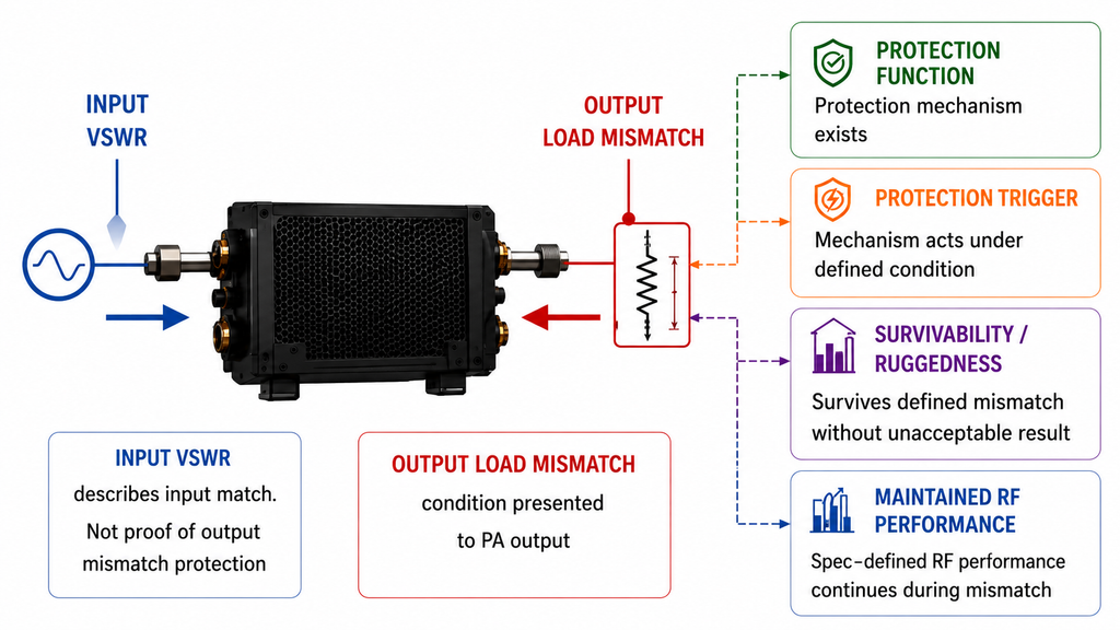
Input VSWR Is Not Output Load-Mismatch Protection
Input VSWR describes the match at the amplifier input. It does not prove that the output can tolerate a mismatched antenna, feeder, filter, switch, or other downstream load.
Output load mismatch refers to the load condition presented to the PA output. A related protection function may detect reflected power or another internal condition and respond with an alarm, power foldback, mute, shutdown, or another defined action.
Therefore, “VSWR protection included” proves only that a protection function is being claimed. It does not by itself define the trigger, RF action, survivability result, or recovery behavior.
If the supplier cannot state what the claim actually refers to, stop before numerical comparison. The same discipline applies when reading an RF PA datasheet without missing its operating conditions: a protection label or maximum rating has little value until its definition and conditions are clear.
Protection, Ruggedness, and Maintained Output Are Different Claims
A buyer should separate four different meanings:
- Protection function: a protection mechanism exists.
- Protection trigger: the mechanism acts under a defined condition.
- Mismatch ruggedness / survivability: the evaluated hardware survives a defined mismatch without the stated unacceptable result.
- Maintained performance: specified RF performance continues while mismatch is present.
“Survives X:1 VSWR” does not automatically mean “maintains rated output at X:1 VSWR.” Likewise, a “maximum VSWR” may describe an operating boundary, trigger boundary, or survivability condition.
Device-level ruggedness data cannot automatically be treated as a complete RF PA module guarantee.
Classify each supplier statement first. Only claims in the same capability category should move to condition-by-condition comparison.
2. Why Can the Same VSWR Create Different PA Stress?
VSWR Magnitude Does Not Define Reflection Phase
VSWR describes mismatch magnitude, but not the complete load impedance.
For reflection coefficient ,
the VSWR value depends on , not on reflection phase.
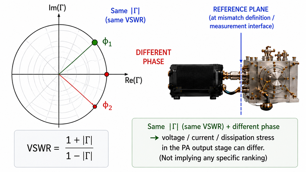
Two loads can therefore have the same VSWR while presenting different impedances to the amplifier. Those phase differences can change voltage, current, and dissipation stress in the PA output stage.
This does not mean that all reflected power simply becomes internal heat. The defensible conclusion is narrower: the same VSWR magnitude does not automatically represent the same PA stress.
For broad ruggedness or survivability claims, phase coverage can therefore be a critical part of the test boundary.
Reference Plane and Phase Coverage Change the Test Meaning
The reference plane is the point where the mismatch condition is defined or measured.
A VSWR specified at the PA connector is not necessarily equivalent to the same VSWR measured after a cable, filter, switch, coupler, or fixture. Those elements can transform both magnitude and phase before the reflection reaches the amplifier.
A meaningful survivability claim should therefore identify the reference plane and, where relevant, the phase coverage. Frequency, RF operating point, waveform, supply, exposure duration, and thermal state must remain attached to the result as well.
If a broad ruggedness claim does not define the relevant reference plane or phase coverage, treat it as not comparable yet rather than assuming equivalent load stress.
3. Which Load-Mismatch Conditions Must Be Defined Before Evaluation?
Two supplier claims should be compared only after the conditions that can change the conclusion are aligned or shown to be reasonably equivalent.
| Evaluation item | Condition that must be defined | Why it changes the decision | Evidence required | If the condition is missing |
|---|---|---|---|---|
| Frequency | Test range and critical frequencies | Stress and protection behavior can vary with frequency | Specification or test record | Do not extend a single-frequency result |
| Waveform / duty cycle | CW, pulsed, or modulated condition | Peak, average, and thermal stress can change | Defined test condition | Restrict the claim to the known waveform |
| RF operating point | Output condition and actual PA input drive | Stress depends on how the PA is driven | Operating-point record | Do not compare different operating points directly |
| Supply | Module-side supply condition | Supply can affect stress and protection response | Specification or test condition | Request clarification |
| Mismatch magnitude | Defined VSWR, return loss, reflected power, or equivalent | The load boundary must be unambiguous | Specification or test record | Do not infer a numerical limit |
| Phase range | Tested phase point, range, or coverage | Equal VSWR can produce different stress | Phase-coverage evidence | Restrict the conclusion to demonstrated coverage |
| Load / test method | Load, tuner, or mismatch fixture | Test implementation affects the presented load | Test-method description | Clarify before strong comparison |
| Reference plane | Point where mismatch is defined | Intervening RF networks transform impedance | Drawing or test definition | Stop strong comparison |
| Duration / repetition | Exposure time and repetition | Brief and sustained mismatch are different conditions | Duration record | Do not extrapolate to longer exposure |
| Thermal state | Cold, transient, or stabilized condition; cooling | Thermal state changes available stress margin | Thermal test condition | Do not extend cold-state evidence to hot steady state |
| Pre-/post-test baseline | Relevant checks before and after exposure | Survivability or degradation needs a comparison basis | Baseline and post-test results | “No degradation” remains undefined |
| Hardware / firmware scope | Applicable revision and configuration | Protection behavior may change by version | Version-controlled evidence | Do not transfer evidence automatically |
The result should be classified as comparable, partially comparable, or not comparable yet.
If a conclusion-changing condition is missing or cannot be reasonably normalized, do not force a supplier ranking. Request the missing evidence instead.
A controlled dummy-load result is only a baseline. Once cables, filters, connectors, and the antenna are added, the impedance presented to the PA can change, so dummy-load testing and the installed RF path should not be treated as equivalent load conditions.
4. What Should the Amplifier Do When Load Mismatch Occurs?
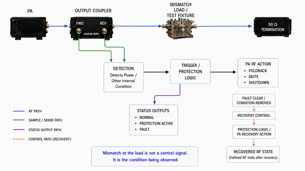
A useful protection definition follows one chain:
mismatch condition → detection → trigger → RF action → alarm/status → fault clearance → recovery → recovered RF state
Detection and Valid Measurement Conditions
The supplier should identify what the amplifier detects and when that measurement is valid.
A design may use forward power, reflected power, their relationship, or another internal quantity. If VSWR is derived from forward and reflected measurements, the ratio should not be extrapolated without limit at very low forward power or near the effective detector range.
The buyer therefore needs both the measured quantity and the trigger meaning. If either is undefined, the function is not yet sufficiently specified for acceptance.
Foldback, Mute, or Shutdown
After a trigger, the amplifier may reduce power, mute RF, shut down, or use another defined response.
No one action is automatically superior. The relevant procurement question is what happens to RF output, what status is reported, and what the external controller must do next.
Load mismatch is only one branch of the protection state machine. Temperature, voltage, current, and reflected-power faults can have different triggers, RF actions, alarms, and recovery rules, which is why complete RF PA protection logic validation must distinguish each protection branch rather than treating them as one generic function.
Recovery, Latch, and Retry Behavior
Protection is incomplete unless recovery is also defined.
The buyer should know whether the fault latches, whether recovery is automatic or commanded, how repeated faults are handled, and what RF state exists after recovery.
Clearing the mismatch fault does not necessarily mean RF can resume immediately; controller state, command order, and AT command timing after protection recovery can still determine when the system returns to its intended operating state.
For a specific RF SKYPOWER configuration, trigger thresholds, foldback amount, latch behavior, and recovery timing require model- and project-specific confirmation.
5. How Should You Read VSWR Ruggedness and Survivability Claims?
A high VSWR number has procurement meaning only when its conditions and result definition are known.
A survivability claim should identify the applicable frequency, signal, RF operating point, supply condition, mismatch magnitude, phase coverage, exposure duration, thermal state, and the exact result being claimed.
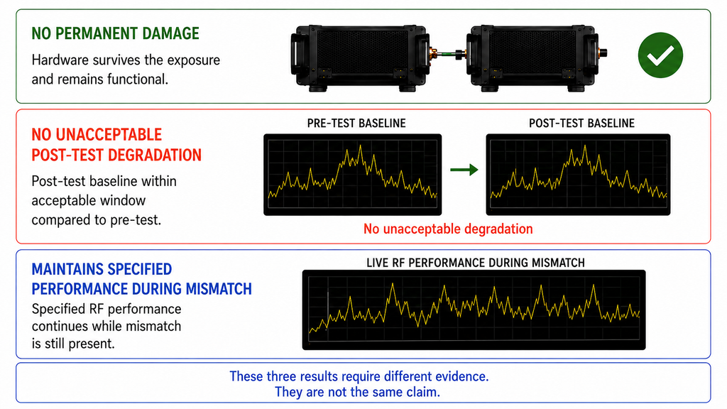
Three conclusions must remain separate:
- no permanent damage;
- no unacceptable post-test degradation;
- maintains specified performance during mismatch.
They require different evidence.
Evidence scope matters as much as the result. Device-level data supports the device and its test conditions, not automatically the complete module. Representative module characterization supports the represented design and sample scope, not every delivered unit.
When Two VSWR Protection Claims Are Not Comparable Yet
Do not rank suppliers by X:1 VSWR alone.
First align the claim type. Then align the conditions that materially affect the conclusion. If the claim type and decisive conditions match, the results may be comparable. If some relevant boundaries remain unresolved, they are partially comparable. If a missing condition could change the conclusion, they are not comparable yet.
A stronger-looking number should never be converted into a stronger project guarantee without correspondingly stronger evidence.
6. What Evidence Is Sufficient for Supplier Evaluation or Acceptance?
Evidence should match the procurement decision.
A datasheet or formal specification supports initial function and scope screening. Engineering characterization supports design behavior under defined conditions. A formal test or qualification record supports a specific conditioned survivability or performance claim.
A serial-number-linked record serves a different purpose: proving something about a particular delivered unit when the contract requires unit-level traceability.
Representative evidence cannot automatically become unit-level evidence. Conversely, a high-stress design qualification should not automatically be repeated on every unit unless the project specifically requires that verification.
Video can support visible setup, state, alarm, or process evidence, but it cannot replace a defined test report when the decision depends on documented conditions and results.
If the model, frequency, operating point, thermal state, test condition, or sample scope does not match the current procurement question, stop before upgrading the conclusion.
Acceptance evidence should remain tied to the protection behavior being verified. A complete RF PA protection acceptance framework must distinguish trigger conditions, RF response, status reporting, recovery, and evidence scope rather than treating one successful event as proof of the entire protection system.
Module-level protection evidence also does not remove installation risk. Antennas, feeders, connectors, and environmental changes can still create high-reflection conditions in service, so field VSWR failure prevention remains a separate system-level reliability concern.
What Should the RFQ Specify for VSWR Protection and Recovery?
A useful RFQ should define the application condition, required protection behavior, and required evidence together. It does not need a separate paragraph for every field.
- Frequency and RF operating point: specify frequency range and critical points, target RF output and its definition, actual available input drive, and module-side supply.
- Signal condition: specify waveform, bandwidth, duty cycle, and other signal conditions that materially affect the mismatch requirement.
- Load-mismatch boundary: define normal load, required VSWR or equivalent mismatch condition, applicable reference plane, required phase coverage, and exposure duration.
- Thermal condition: define expected thermal state and cooling condition for the requirement.
- Protection and recovery: define the required RF action, alarm/status visibility, latch or retry behavior, and the expected RF state after recovery.
- Evidence: state whether the project requires specification-level evidence, characterization, formal conditioned testing, or acceptance records.
- Unit-level traceability: state whether any required evidence must be linked to the serial number of a delivered unit.
For each grouped requirement, the supplier should confirm the applicable condition and provide evidence at the level required by the project. Do not insert default VSWR thresholds, response times, or recovery times that have not been defined by the application or supported by formal evidence.
Use the completed checklist as the supplier-facing requirement set. The Custom RF Power Amplifier Modules page can help identify candidate product families, while project-specific protection, recovery, and evidence requirements should be confirmed through the RF SKYPOWER engineering / RFQ path.
| RF PA Module | Frequency Range | Output Class | Relevant Protection Evidence | Next Step | View Datasheet |
|---|---|---|---|---|---|
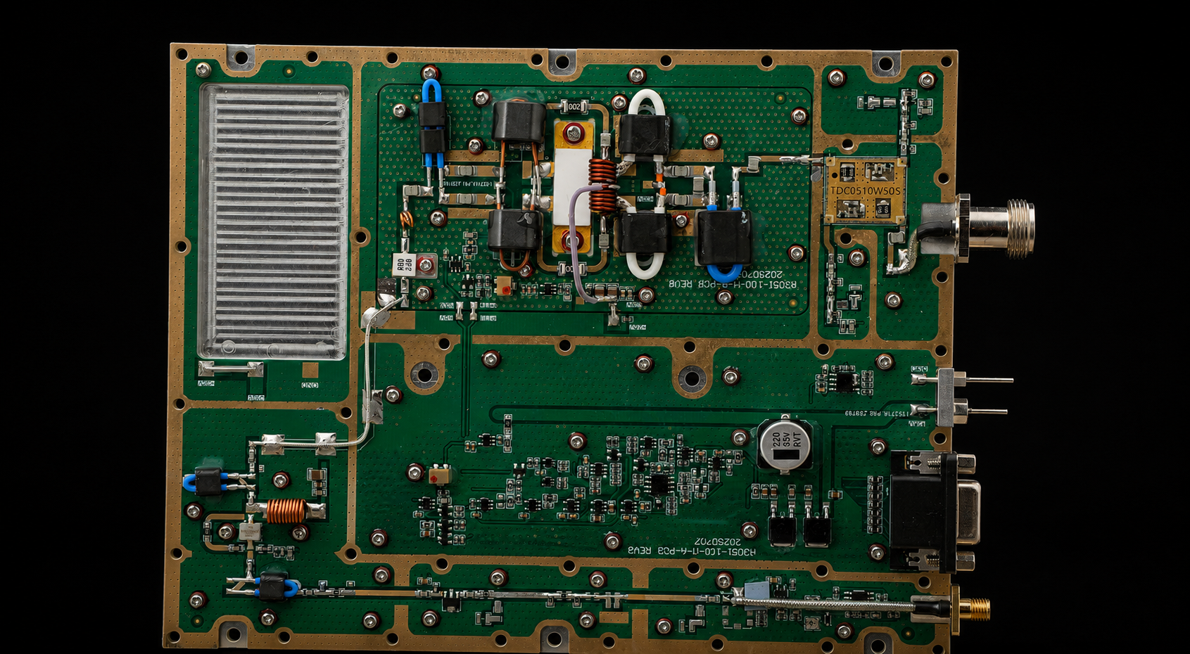
|
30–512 MHz | 100 W | Output open/short protection behavior documented | View Series | View Datasheet |
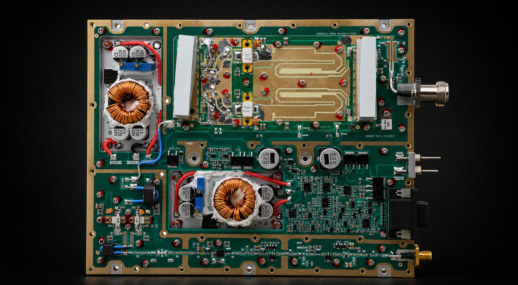
|
300–1200 MHz | 100 W | Output open/short protection behavior documented | View Series | View Datasheet |
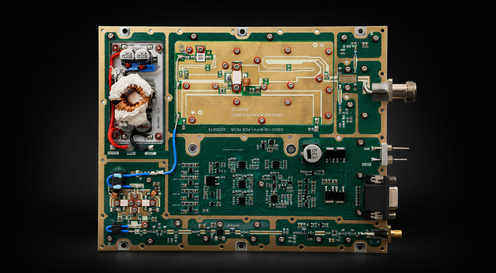
|
300–1700 MHz | 100 W | Output open/short protection behavior documented | View Series | View Datasheet |
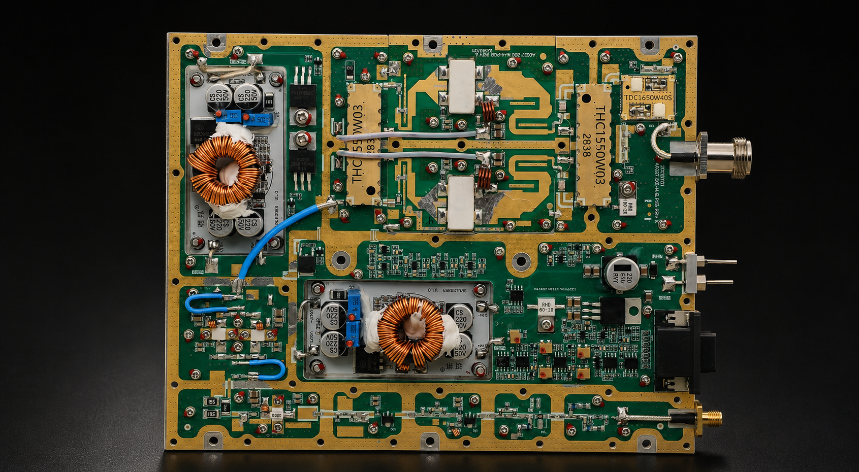
|
300–2700 MHz | 100 W | Output open/short protection behavior documented | View Series | View Datasheet |
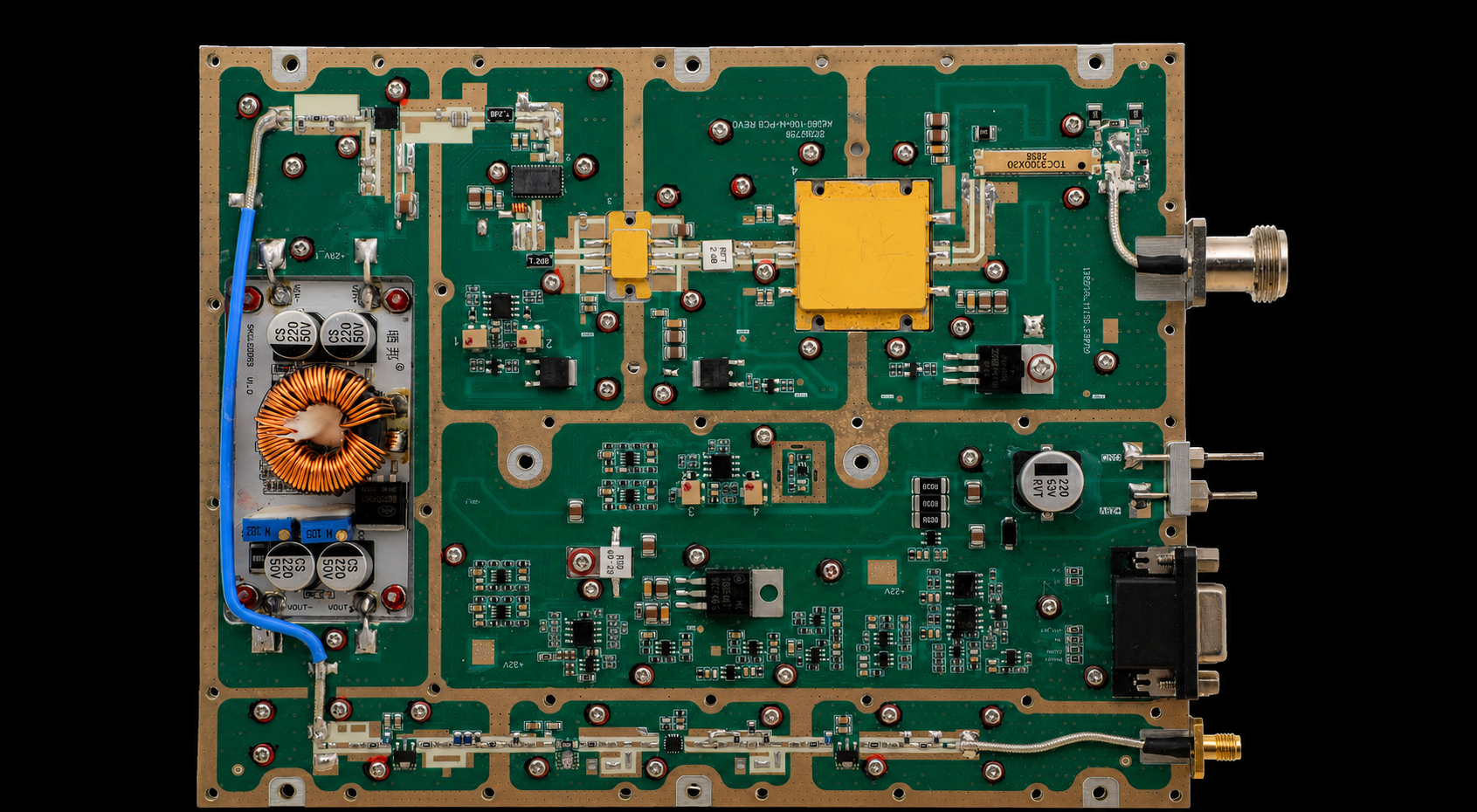
|
2000–6000 MHz | 100 W | Output open/short protection behavior documented | View Series | View Datasheet |
Conclusion
RF power amplifier VSWR protection should be judged by whether the mismatch condition, detection, trigger, RF action, status, recovery, and evidence are defined within the same boundary—not by a protection checkbox or standalone VSWR number.
A defensible comparison requires the conditions that materially affect the claim, including RF operating point, mismatch definition, relevant phase coverage, reference plane, exposure duration, thermal state, recovery behavior, and evidence scope.
This framework can determine whether a supplier claim is defined well enough to compare. It cannot establish a universal safe VSWR, trigger threshold, recovery time, or no-damage limit for a specific model without corresponding evidence.
The main error to avoid is treating “survives X:1 VSWR” as proof that rated performance is maintained at every frequency, phase, power level, and thermal condition.
Before supplier selection, classify each claim as comparable, partially comparable, or not comparable yet, and record the evidence still missing. If project-specific confirmation is then required, submit that completed requirement set for engineering review rather than trying to infer suitability from a standalone VSWR claim.