










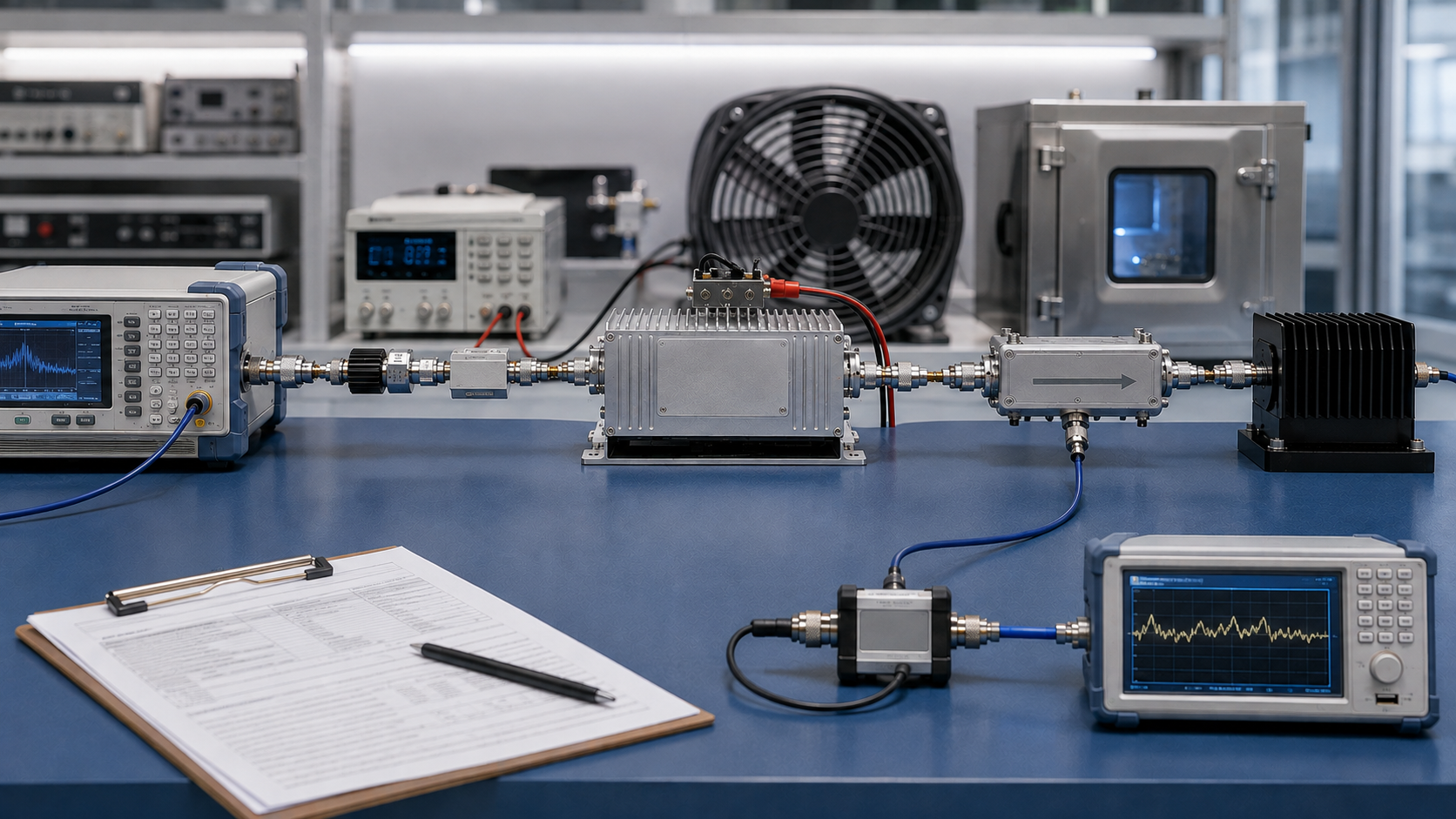
Valid RF power amplifier testing is defined less by the number of measurements than by whether the test objective, operating conditions, reference planes, measurement method, and acceptance basis are established before the result is interpreted.
The practical sequence is simple: define what must be proved, freeze the RF, DC, load, and thermal conditions, select the necessary measurements, then check comparability and the approved acceptance basis before making a decision.
A result proves only what was actually tested: the stated frequency or range, waveform, operating point, load, thermal state, and evidence scope.
1. What Are You Trying to Prove With the RF PA Test?
Start with the decision, not the instrument list.
Characterization maps behavior under selected conditions. Design verification checks defined engineering requirements. Supplier comparison requires sufficiently aligned test conditions before ranking. Production acceptance applies approved pass/fail requirements to a defined unit or batch. Troubleshooting isolates abnormal behavior and may use conditions that are not valid for acceptance.

These purposes require different evidence. A measurement can show what happened without proving that a formal requirement was satisfied.
Acceptance limits must come from an applicable specification, RFQ, contract requirement, approved engineering standard, or project test plan. Typical, nominal, target, minimum, and contractual values are not interchangeable.
Before selecting measurements, record:
- what is being tested;
- what must be proved;
- where the requirement comes from;
- what decision the result will support.
If the test purpose or acceptance source is unclear, stop at characterization. Do not create a formal pass/fail rule after seeing the data.
When the task moves from general testing to shipment-release evidence, use the dedicated RF PA acceptance checklist.
2. Which Test Conditions Must Be Fixed Before Measurements Begin?
Test conditions determine what a result means and whether another result can be compared with it.
Pin is the actual RF input power at the defined PA input reference plane, not automatically the signal-generator setting. Pout is output power at the defined output reference plane, not automatically the raw value displayed by an instrument elsewhere in the chain.
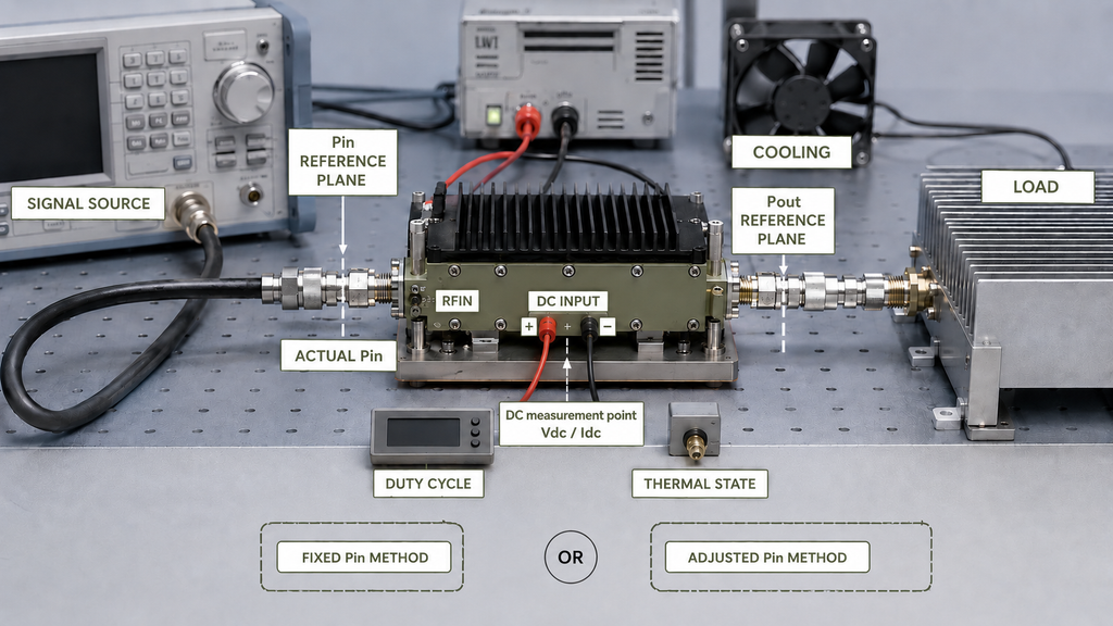
Also distinguish fixed Pin, where input drive is held constant, from adjusted Pin, where drive is changed to reach another target such as Pout. These methods answer different questions.
A cold-state result and a thermal steady-state result are also different evidence. Cooling, mounting, duty cycle, DC conditions, load, and test duration can change the result.
RF PA Test Condition Record
| Test Item | Current Definition | Unit / Status | Reference Plane or Location | Locked? | Notes |
|---|---|---|---|---|---|
| Test objective | Project-defined | Decision purpose | — | Yes / No | State what must be proved |
| DUT / version | Project-defined | ID / revision | DUT | Yes / No | Record relevant configuration |
| Frequency points | Project-defined | Frequency | RF path | Yes / No | Use required test points |
| Signal and power definition | Project-defined | Waveform / state | Source / PA input | Yes / No | Define the applicable power convention |
| Actual Pin | Project-defined | RF power | PA input reference plane | Yes / No | Do not substitute source setting |
| Pin reference plane | Project-defined | Location | PA input path | Yes / No | Define where Pin applies |
| Pout reference plane | Project-defined | Location | PA output path | Yes / No | Define where Pout applies |
| Vdc / Idc measurement point | Project-defined | V / A | Defined DC location | Yes / No | Record measurement location |
| Load | Project-defined | State | PA output path | Yes / No | State the load condition |
| Duty cycle | Project-defined | State | DUT operating condition | Yes / No | When applicable |
| Cooling | Project-defined | State | Mounting / cooling boundary | Yes / No | Record actual condition |
| Thermal state | Cold / defined stabilized state | State | DUT | Yes / No | Do not mix thermal states |
| Test duration | Project-defined | Time | Test procedure | Yes / No | Tie duration to the requirement |
| Calibration basis | Defined method | State | Measurement chain | Yes / No | Record applicable corrections |
| Protection state | Project-defined | State | DUT | Yes / No | Record relevant configuration |
Comparison requires sufficient alignment of these conditions. If actual Pin, a critical reference plane, the load, or the thermal state cannot be established, stop direct comparison until the gap is resolved.
When input-path uncertainty becomes the main question, use the specialist guidance for actual Pin at the PA input. Thermal stabilization and dummy-load versus installed-path questions should likewise move to their specialist procedures rather than being expanded here.
3. How Should an RF Power Amplifier Test Setup Be Built and Calibrated?
A repeatable RF power amplifier test procedure starts with a test chain whose reference planes and correction boundaries are explicit:
Signal source → characterized input path → [Pin reference plane] → RF PA → [Pout reference plane] → coupling / attenuation path → RF measurement equipment, with the main RF output terminated in a controlled load and Vdc / Idc monitored at defined DC points.
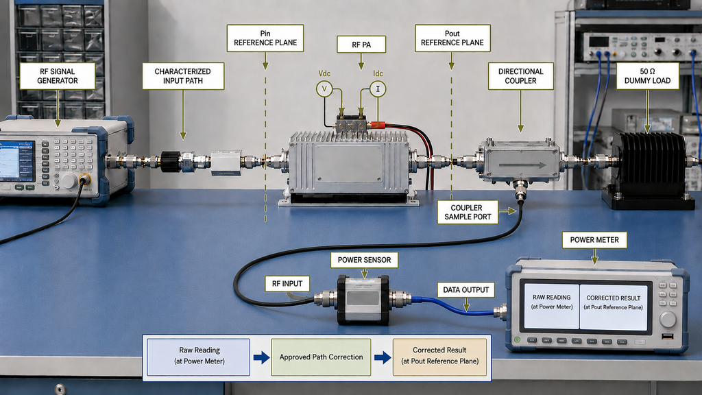
The important distinction is between where an instrument measures and where the final value is claimed.
A raw reading is the value observed at the instrument. A corrected result is the value after the approved path correction has been applied to the specified reference plane.
Before testing, mark the Pin reference plane, Pout reference plane, DC measurement points, and correction boundaries. If path loss, coupling relationship, or the reference plane cannot be established, do not report the instrument display as PA-terminal Pin or Pout.
Detailed Pin calibration and installed RF-path behavior should remain with their specialist test procedures.
4. Which RF PA Measurements Should You Run—and in What Order?
There is no universal measurement set for every RF PA.
A practical order is:
confirm DUT identity and configuration → establish a low-risk baseline → confirm the intended Pin/Pout operating point → run required large-signal measurements → add applicable waveform-specific spectral or linearity measurements → measure DC and efficiency → establish the required thermal state → route specialist protection or other project-specific tests as needed.
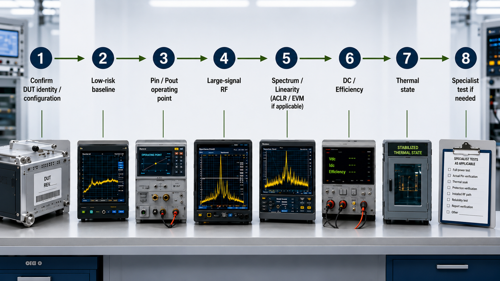
An RF amplifier output power test determines whether the required RF output is produced under the stated conditions; gain and compression address input-to-output behavior; input match addresses the PA input condition; frequency response covers tested frequency points; harmonics and spurious measurements address spectral content; DC and efficiency address electrical conversion; and thermal measurements address performance at the required thermal state.
ACLR and EVM belong only where the modulation and system requirements make them relevant. They are not universal RF PA acceptance items.
Comparability must be judged separately for each measurement. Comparable Pout evidence does not automatically make gain, efficiency, spectrum, or thermal results comparable.
RF PA Measurement–Acceptance Matrix
| Test Item | Decision Question | Test Conditions | Reference Plane | Result / Evidence Type | Acceptance Basis | Limit Source | Evidence Scope | Prohibited Extrapolation |
|---|---|---|---|---|---|---|---|---|
| Output power | Does the PA produce the required output? | Defined frequency, waveform, actual Pin, load, DC, thermal state | Defined Pout plane | Corrected RF result | Project acceptance rule | Specification / RFQ / approved test plan | Tested condition | Untested band, waveform, thermal state, or installed path |
| Gain / compression | Is input-to-output behavior acceptable? | Defined drive, waveform, DC, load, thermal state | Defined Pin and Pout planes | Measured / derived RF result | Project acceptance rule | Approved requirement | Tested drive range | Untested drive or thermal conditions |
| Input match | Is PA input behavior acceptable? | Defined frequency and operating state | PA input plane | RF measurement | Project-specific rule | Approved requirement | Tested condition | Output quality, efficiency, or thermal performance |
| Frequency response | Does required behavior hold across tested points? | Aligned conditions at each frequency | Defined RF plane | Multi-point RF evidence | Project acceptance rule | Approved requirement | Tested frequencies | Frequencies not tested |
| Harmonics / spurious | Is spectral behavior acceptable? | Defined waveform and operating point | Defined output plane | Spectrum evidence | Applicable system rule | Approved requirement | Tested signal and state | Different waveforms or powers |
| ACLR / EVM | Is applicable modulated-signal performance acceptable? | Defined modulation and operating point | Defined measurement boundary | Waveform-specific evidence | Applicable communication rule | Approved requirement | Tested waveform | Unrelated RF PA applications |
| DC / efficiency | Is DC and conversion behavior acceptable? | RF operating point, Vdc, Idc, load, thermal state | Defined RF and DC points | Measured / calculated result | Project acceptance rule | Approved requirement | Tested operating state | Different RF or thermal states |
| Thermal-state performance | Does performance remain acceptable after stabilization? | Defined cooling, mounting, load, duration | Defined RF plane | Stabilized-state result | Project thermal rule | Approved requirement | Tested thermal condition | Other cooling or mounting conditions |
| Protection behavior | Does the PA respond correctly to a defined abnormal condition? | Specialist fault condition | Procedure-defined | Event / state evidence | Protection requirement | Approved project requirement | Tested fault case | Other faults or general reliability |
Choose only the measurements needed to answer the project question. A power result cannot substitute for spectrum, efficiency, thermal, or linearity evidence.
When the decision requires an RF power amplifier swept test at full power across frequency, move to full-power RF PA testing rather than expanding this general framework into the specialist procedure. Thermal and protection questions should likewise use their specialist procedures.
5. When Are Two RF PA Test Results Actually Comparable?
Supplier comparison starts with the test basis, not the numbers. Similar units and similar reported values do not create direct comparability when critical conditions differ.
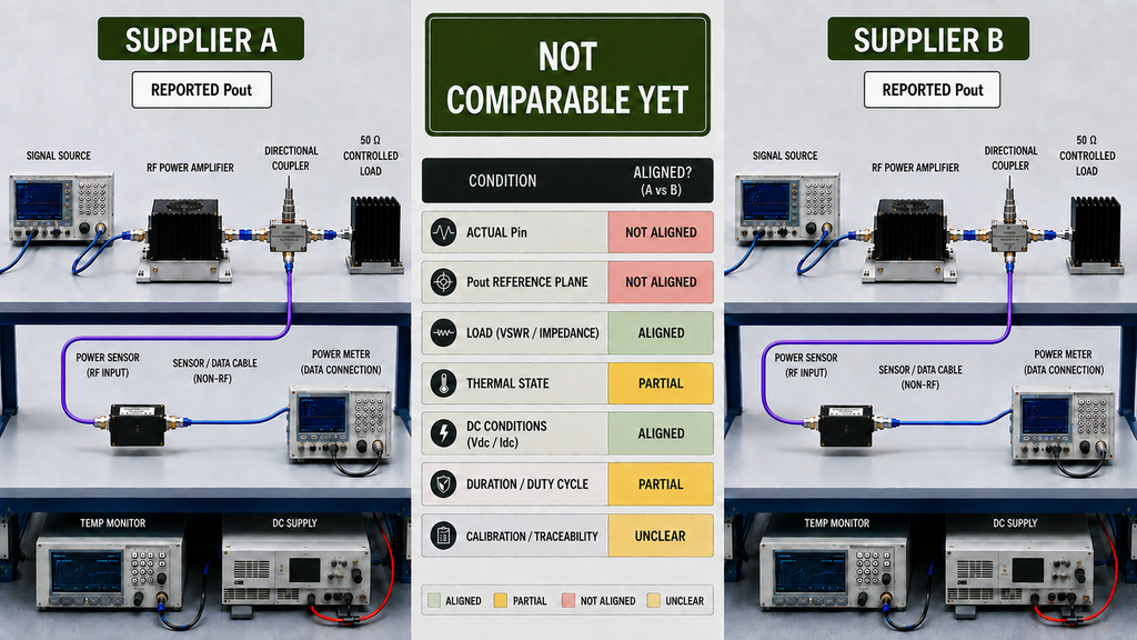
Supplier Test Result Comparability Checklist
| Check Item | Supplier A Condition | Supplier B Condition | Aligned? | Impact | Final Comparability Status |
|---|---|---|---|---|---|
| Frequency | Record | Record | Yes / No / Partial | May change RF performance | — |
| Waveform / power definition | Record | Record | Yes / No / Partial | May represent different signal or power conditions | — |
| Actual Pin | Record | Record | Yes / No / Partial | Different drive can invalidate ranking | — |
| Operating point | Record | Record | Yes / No / Partial | Data may represent different PA states | — |
| Pout reference plane | Record | Record | Yes / No / Partial | Different boundaries can shift reported Pout | — |
| Load | Record | Record | Yes / No / Partial | Load condition may change RF behavior | — |
| DC condition | Record | Record | Yes / No / Partial | Supply differences may change the operating state | — |
| Duty cycle | Record | Record | Yes / No / Partial | Changes electrical and thermal stress | — |
| Thermal state | Record | Record | Yes / No / Partial | Cold and stabilized results are not equivalent | — |
| Cooling | Record | Record | Yes / No / Partial | Cooling can change thermal performance | — |
| Test method | Record | Record | Yes / No / Partial | Different procedures may produce non-equivalent evidence | — |
| Calibration / correction | Record | Record | Yes / No / Partial | Correction differences can shift reported values | — |
| Hardware / configuration | Record | Record | Yes / No / Partial | Different revisions may represent different product states | — |
| Evidence scope | Sample / batch / S/N-linked | Sample / batch / S/N-linked | Yes / No / Partial | Determines claim strength | — |
Assign one status after the review:
Comparable — the critical definitions and conditions are sufficiently aligned.
Partially Comparable — only the overlapping range or condition is sufficiently aligned.
Not Comparable Yet — a critical condition or definition is missing or cannot be reasonably aligned, so ranking should stop.
Not Comparable Yet is an evidence decision, not a product failure.
If the mismatch comes from Pin, thermal state, load path, or test method, resolve the corresponding specialist issue before ranking the results.
6. How Do You Define RF PA Acceptance Criteria?
An RF amplifier acceptance test is executable only when the parameter, requirement source, test conditions, measurement method, reference plane, limit, evidence scope, and decision rule are connected before formal testing begins.
A typical or nominal value is not automatically a minimum acceptance limit. The limit must come from the applicable specification, RFQ, contract requirement, approved engineering standard, or project test plan.

A complete acceptance rule can be structured as:
[Parameter] shall meet [approved limit] under [defined frequency, waveform, drive, DC, load, and thermal conditions], measured by [approved method] at [defined reference plane], with [applicable uncertainty or guard-band rule] and [defined evidence scope and retest or disposition rule].
This guide does not create universal RF PA limits. Where uncertainty, guard-band, or retest logic applies, define it before the result is known.
Complete the measurement–acceptance matrix before formal testing. Pass/fail results are directly comparable only when the acceptance basis and relevant test conditions are the same or reasonably aligned; different limits, reference planes, or operating states should not be treated as equivalent acceptance evidence.
If the limit source or applicable conditions are undefined, stop before issuing a formal pass/fail conclusion.
For shipment-level release evidence, continue with the RF PA acceptance checklist defined earlier rather than expanding this general framework into a complete release procedure.
Once the project conditions are defined, RF SKYPOWER can use frequency, Pout, Pin, waveform, DC, load, cooling, thermal state, and acceptance-evidence requirements as inputs to engineering review or RFQ. That review does not itself establish that a specific model satisfies the project.
Match Your Test Conditions to an RF PA Product Family
Use the required operating frequencies as the first routing step—not as proof of final suitability. Confirm the waveform, actual Pin, Pout reference plane, DC conditions, load, duty cycle, cooling, thermal state, and acceptance evidence before model selection.
RF PA Product Routing
Match Your Test Conditions to an RF PA Product Family
Use the required operating frequencies as the first routing step—not as proof of final suitability. Confirm the waveform, actual Pin, Pout reference plane, DC conditions, load, duty cycle, cooling, thermal state, and acceptance evidence before model selection.
Listed product classes: 30 W · 50 W · 100 W · 150 W · 200 W. Treat the listed power class as a product-family starting point; the required Pout still needs to be evaluated at the project-defined reference plane and operating conditions.
- Required frequency points
- Waveform and power definition
- Actual Pin at the PA input
- Target Pout and reference plane
- Vdc and operating mode
- Load and duty cycle
- Cooling and thermal state
- Acceptance and report evidence
Product-family coverage does not by itself confirm that a specific module meets the required waveform, output, thermal, load, protection, or acceptance conditions. Final configuration should be reviewed against the project test requirements.
7. What Evidence Should the Final RF PA Test Record Contain?
An RF amplifier test report should identify the DUT and configuration, preserve the relevant test state, show how the reported result was derived, and define the scope of evidence.
Record the DUT identity and version, test date, relevant equipment identity and calibration status, correction state, frequency and signal definition, actual Pin, raw and corrected results, reference planes, Vdc and Idc, load, duty cycle where applicable, cooling and thermal state, applicable acceptance limit and source, and final disposition.
Two reports should not be treated as comparable evidence until the DUT identity, configuration, test conditions, reference planes, and evidence scope are clear.
Sample evidence applies to the tested sample. Batch evidence applies only to the authorized batch and sampling scope. S/N-linked evidence is traceable to a specific serial-numbered unit and its configuration, conditions, and result.
These levels cannot be automatically upgraded. A representative sample does not prove an entire batch, and batch evidence does not automatically prove every delivered S/N.
If a claim is unit-specific but the report cannot be tied to the relevant S/N or configuration, stop the unit-level acceptance decision. A one-report-per-unit approach is appropriate only where the project requires unit-level evidence.
When report identity, revision, configuration, or delivery traceability becomes the primary question, use the dedicated RF PA test report verification procedure.
8. When Should You Stop the General Test and Use a Specialist Procedure?
Stop the general framework when the unresolved question requires specialist conditions or evidence.
Full-power cross-frequency behavior belongs to the full-power test procedure; uncertain actual Pin belongs to input-power verification; thermal steady-state behavior belongs to thermal-soak testing; protection or mismatch response belongs to protection testing; dummy-load versus installed-path behavior belongs to RF-chain testing; burn-in or long-duration stress belongs to reliability testing; and report identity or unit traceability belongs to test-report verification.
Mentioning one of these topics in a general test plan does not complete the specialist validation. Once the decision depends on specialist conditions or evidence, route the work rather than expanding the parent procedure.
Conclusion
Correct RF power amplifier testing starts by defining what must be proved, fixing the operating conditions and reference planes, and establishing the acceptance basis before interpreting the result.
This framework can determine whether test evidence is meaningful and comparable, but it cannot create project-specific limits, suitability decisions, protection thresholds, or acceptance values. A single-frequency, cold-state, sample, or dummy-load result must remain within that evidence scope.
Do not rank two suppliers simply because they report the same Pout. If waveform, actual Pin, operating point, reference plane, load, DC condition, thermal state, or test method cannot be sufficiently aligned, Not Comparable Yet is the correct conclusion.
Before requesting final supplier data, complete the test-condition record and measurement–acceptance matrix. For an RF SKYPOWER engineering review or RFQ, provide the frequency and test points, waveform, Pout, Pin, Vdc, load, duty cycle, cooling and thermal requirements, applicable spectral or protection requirements, reference planes, acceptance-limit source, and required sample, batch, or S/N-linked evidence scope. Engineering review does not itself confirm specific-model suitability or final acceptance.