











Gain flatness acceptance is defensible only when the gain definition, measurement state, frequency range, reference planes, calculation method, and acceptance basis are defined. RF power amplifier gain flatness describes how gain varies across that specified frequency range under the stated test condition.
A ±dB number alone is not enough. Small-signal S21 gain flatness and operating-drive gain flatness are different evidence, and the allowable limit must come from the project specification, RFQ, contract, or approved test plan—not from a universal RF PA flatness number.
Start by defining exactly what the flatness value represents.
1. What Does RF Power Amplifier Gain Flatness Actually Measure?
Gain flatness measures how the gain of one amplifier changes across a defined frequency range under a defined test condition.
If the gain at frequency is , a common summary is the peak-to-peak gain variation:
where and are the highest and lowest gain values within the stated frequency range.
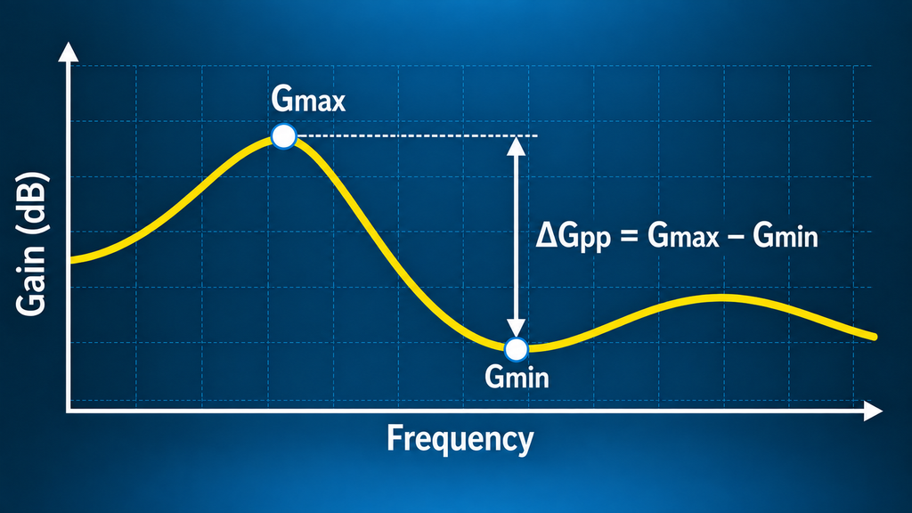
This is not automatically equivalent to a specification written as ±x dB. A ± value may describe deviation from a target, nominal value, average, midpoint, or another declared reference. The reference and calculation rule must therefore be stated with the number.
Gain flatness is also different from gain tolerance. Gain flatness controls variation across frequency for one defined unit and test state. Gain tolerance can instead control allowable gain differences between units or deliveries under a common condition.
Before using a flatness result, the buyer should know:
the applicable frequency range, the gain quantity being evaluated, and the calculation used to produce the reported value.
If the frequency range or calculation rule is unknown, the result is not ready for formal gain-flatness acceptance.
2. Which Gain Flatness Test Are You Running: Small-Signal S21 or Operating-Drive Gain?
An RF amplifier gain test used for flatness acceptance must first define whether it measures small-signal S21 or operating-drive gain. The two answer different engineering questions.
For an RF amplifier frequency response measurement, S21 is the forward transmission coefficient from the input port to the output port in a calibrated VNA setup. Its magnitude in dB can characterize the PA’s small-signal forward gain response across frequency while the amplifier remains in the defined low-drive linear condition.
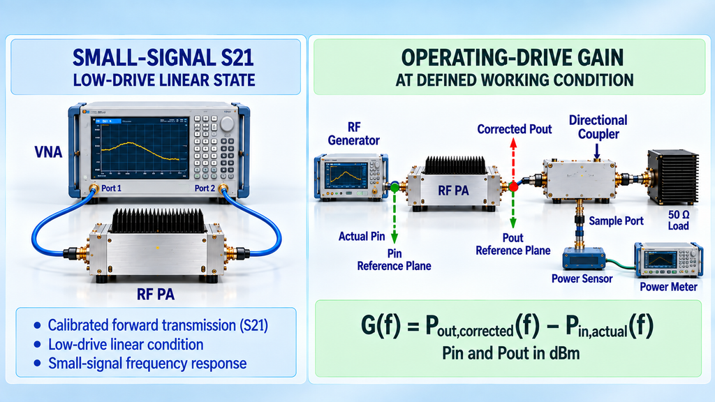
Operating-drive gain is calculated from input and output RF power while the PA operates at a specified drive condition.
A reference plane is the electrical location at which a measured or corrected quantity is defined. Actual Pin is the RF input power present at the specified PA input reference plane, not simply the signal-generator setting. Corrected Pout is the output power referred to the specified PA output reference plane after the approved measurement-path corrections are applied.
| Measurement State | Primary Measurement | Decision Use | Critical Conditions | Can Support | Cannot Prove |
|---|---|---|---|---|---|
| Small-Signal S21 | Calibrated forward transmission response | Low-drive frequency-response characterization | Calibration, reference planes, bias, frequency range, linear operation | Small-signal S21 flatness | Operating-drive or full-power flatness |
| Operating-Drive Gain | Actual Pin and corrected Pout at each frequency | Gain behavior at a defined working drive | Pin/Pout reference planes, signal, load, Vdc, thermal state, correction basis | Operating-drive gain across frequency | Performance outside the stated operating condition |
Small-Signal S21 Flatness
Small-signal S21 flatness characterizes low-drive frequency response; it does not automatically prove gain flatness at operating power.
A calibrated S21 sweep can show how small-signal forward gain changes across the specified band. However, compression, supply behavior, load interaction, and thermal state can alter the gain response as drive increases.
Small-signal data should therefore support a small-signal decision rather than be promoted into working-power evidence.
For the broader distinction, see small-signal and large-signal RF PA gain.
Operating-Drive Gain Across Frequency
Operating-drive flatness uses actual Pin and corrected Pout at each frequency under the defined working condition.
When Pin and Pout use the same stated power definition and are expressed in dBm:
The resulting values describe operating-drive gain across frequency rather than a small-signal S21 response.
If the project requires evidence at a defined high-power state, the scope may need to move into a swept-frequency full-power RF PA test.
Small-signal and operating-drive results can both be valid, but they are not interchangeable. If the required measurement state or actual Pin definition is unknown, one curve should not be used to accept the other state.
3. What Test Conditions Must Stay Fixed Across the Frequency Sweep?
Frequency points can form one valid gain-flatness result only when the key measurement and operating conditions remain aligned or are corrected to the same approved boundary.
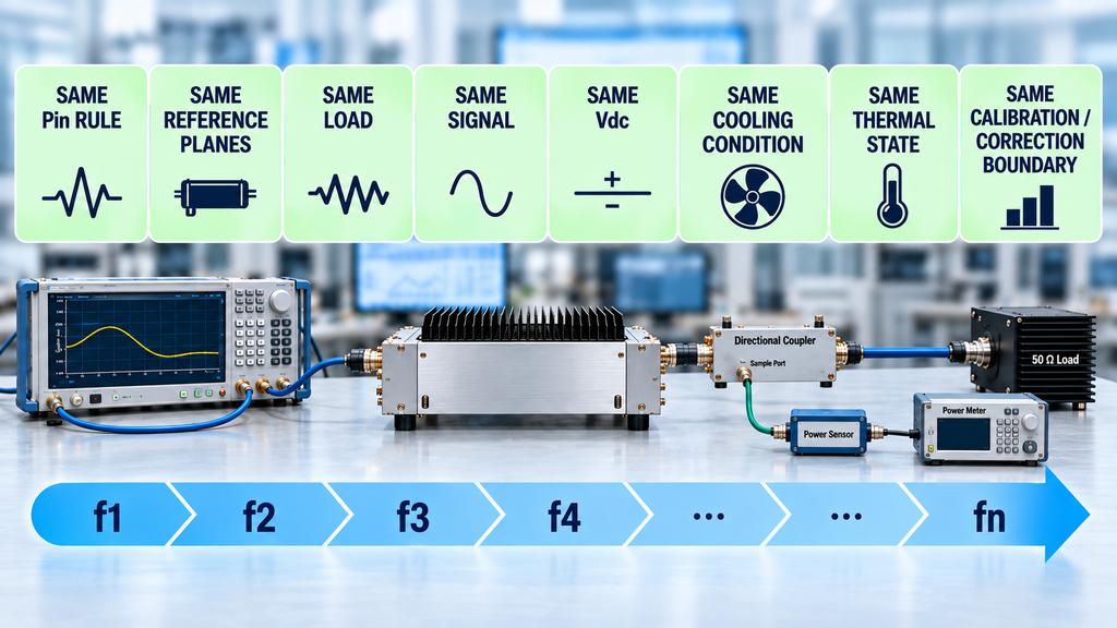
Start with the frequency plan and input-power rule. Signal-generator output is not automatically the actual Pin at the PA because cable loss, fixtures, attenuators, and other source-path elements can vary with frequency.
The output side requires the same control. The measurement location must be defined, and frequency-dependent loss from cables, attenuators, couplers, fixtures, or other approved path elements must be included in the correction method before the result is reported as corrected Pout at the PA output reference plane.
Signal condition, load, Vdc, cooling boundary, and thermal state must also remain defined. Data collected using different waveforms, load conditions, supply conditions, or thermal states should not be combined into one flatness result unless the approved method explicitly makes them comparable.
The purpose is not merely to keep the instruments unchanged. It is to ensure that every gain value represents the PA under the same measurement contract.
The broader framework for RF power amplifier testing applies directly here.
Before calculation, freeze the frequency plan, Pin rule, Pin/Pout reference planes, calibration or correction boundary, signal, load, Vdc, cooling condition, and thermal state.
If actual Pin, a critical reference plane, the main path correction, load condition, or thermal state cannot be established, stop before treating the sweep as directly comparable acceptance data.
4. How Should Gain Flatness Be Calculated and Reported?
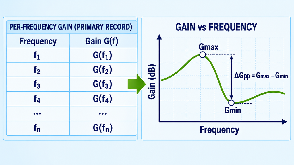
Keep the per-frequency gain values as the primary record, then calculate the approved flatness summary from those data.
Per-frequency data allow a reviewer to identify the maximum and minimum gain, locate band-edge or local deviations, and independently reproduce the flatness result.
For a peak-to-peak definition:
If the project uses a ±dB representation, state the reference. A deviation around a target gain is not automatically equivalent to one calculated around an average, midpoint, nominal value, or another center value.
Average gain may be useful as descriptive information, but it should not replace the individual frequency data. A satisfactory average can still hide a frequency point that exceeds the project limit.
Two flatness values are directly comparable only when their frequency range, measurement points, measurement state, and calculation method are sufficiently aligned.
An isolated ±x dB number without its frequency range or calculation basis is therefore not sufficient for strict acceptance comparison.
5. How Do You Set a Gain Flatness Tolerance Without Inventing a Universal Number?
A gain flatness tolerance must come from an approved project requirement. There is no universal ±dB limit that is correct for every RF power amplifier.
The formal limit should come from a specification, RFQ, contract, or approved test plan.
The required limit can depend on available drive, target output, calibration strategy, usable band-edge margin, waveform, and the operating condition in which the PA must perform. These factors can justify a project-specific requirement, but they do not create a universal RF PA flatness standard.
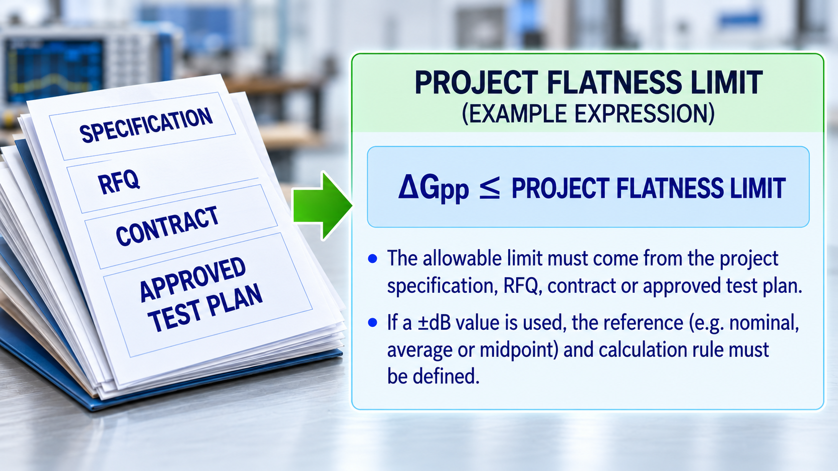
Flatness Limit vs. Batch Gain Tolerance
Gain flatness and batch gain tolerance control different dimensions.
A gain-flatness limit controls how much the gain of one PA may vary across frequency under the stated condition.
Batch gain tolerance controls how much gain may vary between units under a common measurement condition.
A PA can have low across-frequency variation while its absolute gain differs from another unit. A batch can also have tightly grouped gain at one frequency while showing undesirable across-band variation.
When the requirement shifts from one unit’s frequency response to unit-to-unit consistency, see RF PA gain tolerance for batch delivery.
For acceptance, record the flatness limit together with its applicable frequency range, measurement state, calculation rule, and source document.
If the requirement says only “stable gain” without a measurable limit or approved calculation basis, stop the formal conformity decision until the requirement is clarified.
6. How Should Measurement Uncertainty Affect the Acceptance Decision?
A result close to the flatness limit should not be declared an unquestionable pass or fail unless the relevant measurement uncertainty and decision rule are defined.
Measurement uncertainty characterizes the dispersion of values that could reasonably be attributed to the measured quantity under the stated measurement process.
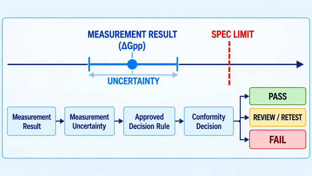
A decision rule defines how the measurement result, applicable uncertainty, and specification limit are used to make a conformity statement.
The rule should be approved before the result is known.
Depending on the approved rule, a result close to the specification boundary may require retest or engineering review rather than an immediate pass or fail. The acceptance region may also differ from the full specification region when uncertainty is explicitly considered.
This does not mean every RF PA project needs the same guard band or uncertainty formula. The conformity rule remains project- or quality-system-specific.
The required decision chain is:
If the flatness limit, applicable uncertainty, or decision rule is missing, report the measured result but do not issue an overconfident formal acceptance statement.
7. What Should the Gain Flatness Acceptance Record Contain?
A gain-flatness acceptance record must preserve the unit or evidence identity, test conditions, per-frequency data, calculation method, limit source, uncertainty treatment, and final result.
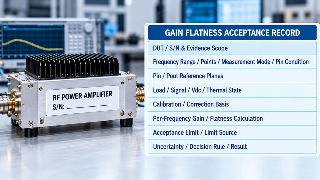
A single line such as Gain Flatness: ±x dB is not enough to show what was measured or what evidence scope the result supports.
When the test accepts a specific delivered unit, identify that unit by S/N or another traceable identity. Representative design-validation data should remain labeled as representative evidence rather than being presented as proof for every delivered unit.
Gain Flatness Measurement and Acceptance Record
| Field | What to Record |
|---|---|
| DUT / S/N or Evidence Scope | Tested unit, S/N, engineering sample, representative sample, or other defined evidence scope |
| Frequency Range / Points | Approved frequency range and actual measurement points |
| Measurement Mode | Small-signal S21 or operating-drive gain |
| Pin Condition | Actual Pin rule or applicable S21 drive condition |
| Pin Reference Plane | Electrical location to which Pin applies |
| Pout Reference Plane | Electrical location to which corrected Pout applies |
| Load | Defined load condition |
| Signal Condition | Waveform or signal type and applicable power definition |
| Vdc | PA supply condition |
| Thermal State | Approved cold, transition, stabilized, or other defined state |
| Calibration / Correction Basis | Calibration method and measurement-path correction boundary |
| Per-Frequency Gain | Gain at every approved frequency point |
| Flatness Calculation | Exact peak-to-peak or approved ±dB calculation rule |
| Acceptance Limit | Applicable project flatness limit |
| Limit Source | Specification, RFQ, contract, or approved test plan |
| Measurement Uncertainty / Decision Rule | Applicable uncertainty treatment and conformity rule |
| Result | Pass, fail, or project-defined review outcome when justified |
| Evidence Scope | Whether the result applies to one unit, a representative sample, or another approved scope |
This record keeps the measurement definition, raw evidence, calculation, and acceptance basis together.
Two records should be compared directly only when their measurement state, frequency range, reference planes, calculation method, and evidence scope are sufficiently aligned.
For delivered-unit acceptance, S/N-linked evidence also prevents a representative engineering curve from being mistaken for proof that every shipped PA passed the same requirement.
Before RFQ release, buyers can review RF power amplifier gain flatness evidence to determine whether supplier data contain enough conditions for meaningful comparison.
The same fields can then be carried into an RF SKYPOWER engineering or RFQ review without implying that every product uses one common flatness limit or report format.
8. What Does Gain Flatness Acceptance Not Prove?
Gain flatness acceptance proves only the defined across-frequency gain requirement under the stated test condition and acceptance rule.
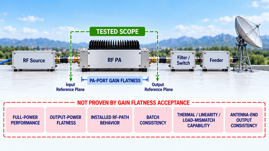
A passing small-signal result does not prove full-power frequency performance. If high-power operation must be demonstrated across frequency, use separate swept-frequency full-power RF PA testing.
Gain flatness also does not prove output-power flatness. Gain describes the relationship between input and output power; output power can show a different frequency response depending on the input condition and operating state.
A PA-port gain-flatness result does not prove antenna-end output consistency because filters, feeders, switches, combiners, connectors, and other installed RF-path elements can add their own frequency-dependent loss.
One S/N does not prove batch distribution.
Gain flatness is not batch gain tolerance.
It also does not independently prove thermal performance, linearity, load-mismatch capability, installed-system performance, or complete shipment acceptance.
When the decision expands from this one parameter to complete delivery evidence, use the broader RF PA acceptance checklist before shipment.
Any conclusion extending beyond the tested frequency range, measurement state, reference planes, thermal condition, unit identity, or evidence scope requires additional evidence.
| Project Need | Appropriate Route | Boundary |
|---|---|---|
| Defined RF PA frequency, power, gain, and flatness requirements | Custom RF Power Amplifier Modules | Product-family coverage does not prove project-specific gain flatness or acceptance |
| A broadband RF amplifier gain flatness requirement is relevant when one PA must cover multiple frequencies or a wider continuous band. | Wideband RF Power Amplifier Modules | Wide frequency coverage does not automatically prove flatness, Pout, or thermal performance across the band |
| Measurement mode, reference planes, operating state, flatness limit, or evidence scope requires project definition | RF SKYPOWER engineering / RFQ review | Engineering review aligns requirements and evidence; it is not a pre-test guarantee of suitability or acceptance |
Conclusion
RF PA gain flatness is acceptance-ready only when the measurement definition, test conditions, calculation method, approved limit, and decision rule are locked.
The result should preserve comparable per-frequency gain data and state exactly what frequency range, measurement state, reference planes, and evidence scope it covers.
A passing flatness result proves only the defined across-frequency gain requirement under those conditions. It does not automatically prove full-power capability, output-power flatness, thermal performance, installed RF-path behavior, batch consistency, or final shipment acceptance.
Before testing or RFQ submission, define the operating frequency range, measurement mode, actual Pin or S21 condition, target Pout where applicable, Pin/Pout reference planes, signal, load, Vdc, duty cycle where relevant, cooling and thermal state, flatness calculation, limit source, uncertainty treatment, decision rule, and required evidence scope.
For an RF SKYPOWER engineering or RFQ review, submit those project conditions together with the required gain and gain-flatness evidence so the requirement can be routed to the appropriate RF PA product family and test-evidence discussion without treating frequency or power coverage alone as proof of project suitability.