











A practical RF PA module definition starts with the product boundary: an RF power amplifier module accepts a lower-power RF signal and DC power, raises the RF signal to a higher usable power level, and exposes defined RF, electrical, thermal, mechanical, and sometimes control interfaces for integration into a larger system. It is not automatically a complete amplifier system: depending on the product, power supply, cooling hardware, protection, monitoring, and control functions may sit inside or outside the module boundary.
That boundary matters in B2B projects. If the product layer is misunderstood, DC, cooling, RF-path, control, or protection responsibilities can remain unresolved until integration. The first task is therefore to understand what an RF PA module does and what the specific product boundary actually includes.
1. What Is an RF Power Amplifier Module?
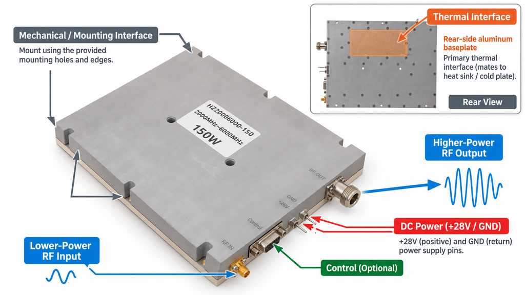
An RF power amplifier module, or RF PA module, accepts a lower-power RF input and delivers a higher-power RF output under defined electrical and operating conditions. Its common core is RF power amplification—not a fixed bandwidth, power class, waveform, or list of internal components.
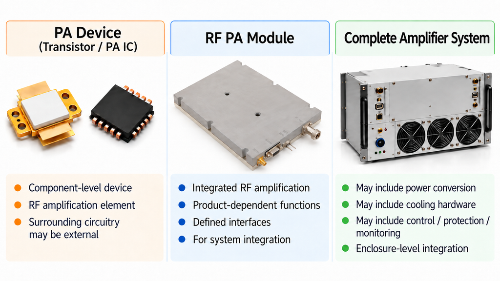
A PA device is a component-level active element, such as a power transistor or PA IC. An RF amplifier module operates at a higher integration level than a PA device, combining the amplification function with a product-dependent set of matching, bias, structural, interface, monitoring, or control functions.
A complete amplifier system has a broader boundary and may also include power conversion, cooling hardware, enclosure-level controls, protection, or other system functions.
The useful definition is therefore functional: an RF PA module is an integrable RF power-amplification building block with defined interfaces. Exactly which supporting functions are included must be confirmed from the specific product documentation.
2. Where Does an RF PA Module Sit in the RF Signal Chain?
An RF PA module is one functional node in a larger RF signal chain. A simplified conceptual path is:
RF Source / SDR / Exciter → RF PA Module → Filter / Switch / Feeder → Load / Antenna
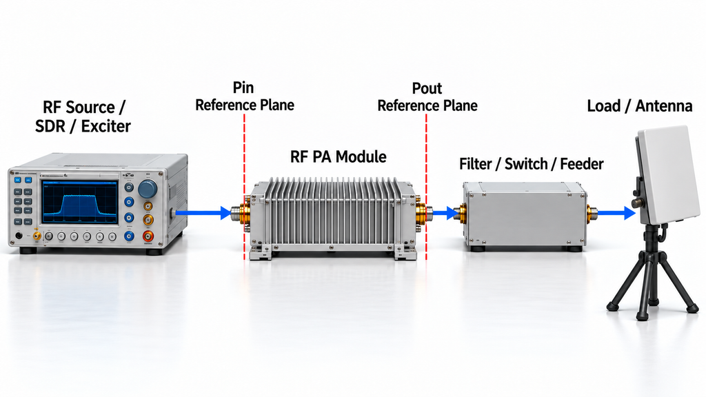
Actual system topology varies, but the boundary principle does not: the PA receives an RF input, increases RF power, and presents an RF output to the downstream path.
A reference plane is the defined electrical location at which an RF quantity is stated. Pin is the RF input power at the defined PA input reference plane, while Pout is the RF output power at the defined PA output reference plane.
That distinction matters because PA-port Pout is not automatically antenna-end or final-load power. Filters, switches, connectors, cables, feeders, and other downstream elements can introduce loss or frequency-dependent behavior.
RF is also only one responsibility path. DC supply, cooling, control, monitoring, and protection can enter through separate interfaces, and some of those responsibilities may remain outside the module.
These boundaries become important during RF power amplifier integration. If the project needs numerical downstream-path loss, antenna matching, or installation analysis, the problem has moved beyond basic module definition and into system integration.
3. What Is Inside an RF Power Amplifier Module—and What May Stay Outside?
The word module does not define where every supporting responsibility sits.
An RF PA module may integrate matching networks, bias functions, driver circuitry, monitoring, protection, or control interfaces. Another product may leave more of these functions to the external system. Their presence should be confirmed rather than inferred from the product name.
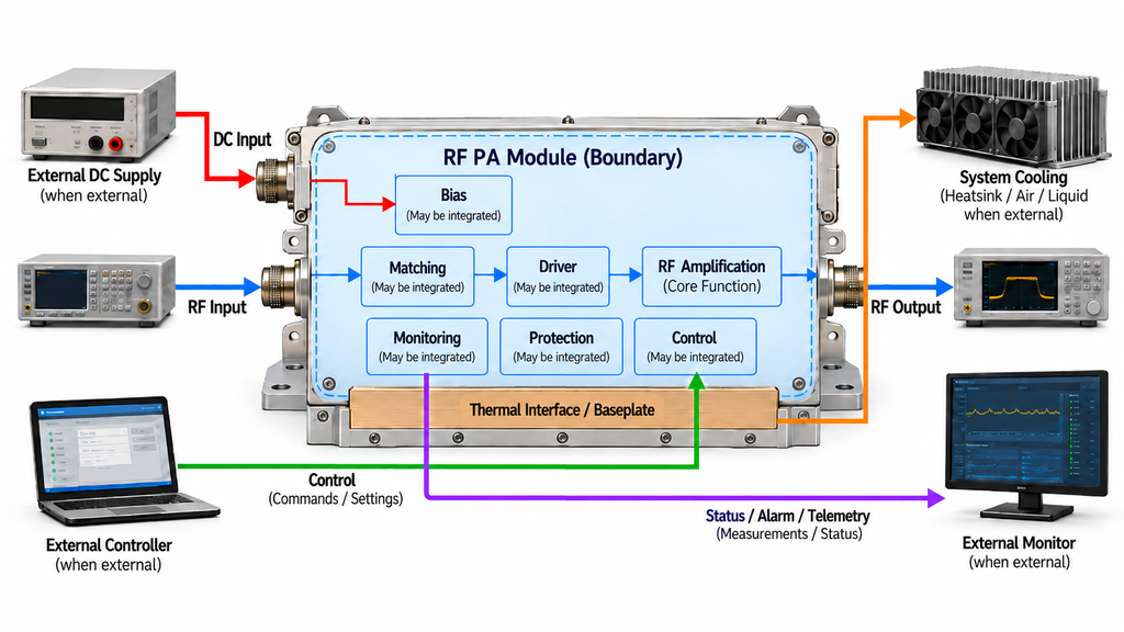
Power and thermal responsibilities vary in the same way. A module may accept regulated DC while leaving the upstream power supply external. It may expose a thermal mounting surface while requiring the system to provide a heatsink, airflow, liquid cooling, or another heat-removal path.
Control and protection boundaries are also product-dependent. Enable, telemetry, status, VSWR-related protection, sequencing, or over-temperature behavior should only be attributed to a module when its documentation defines them.
The buyer’s job is therefore to identify which functions are inside the specific module boundary and which remain external. If the specification or interface documentation does not establish that responsibility, treat it as unresolved rather than assuming it is included.
4. RF PA Module vs. PA Device vs. Complete Amplifier System
PA devices, RF PA modules, and complete amplifier systems occupy different physical and functional boundaries. Their specifications should not be treated as interchangeable.
| Product Level | Typical Functional Boundary | RF Interface | Responsibilities to Confirm | Not Established Automatically |
|---|---|---|---|---|
| PA Device / PA IC | Component-level active element that provides RF gain or power gain; much of the surrounding circuit may remain external. | Device or package terminals, rather than complete module input and output reference planes. | Matching, operating bias, board design, heat removal, monitoring, control, and protection commonly depend on the external design; device-level features vary. | Module connector-plane performance, complete cooling or protection behavior, downstream-path loss, and antenna-end output. |
| RF PA Module | Integrable RF power-amplification building block with a product-specific combination of matching, bias, structure, interfaces, monitoring, or control. | Defined module RF input and output interfaces or reference planes. | DC supply, system cooling, downstream RF path, and any control or protection function not explicitly included in the product documentation. | Antenna-end power, downstream losses, installed-system behavior, or any function outside the stated module boundary. |
| Complete Amplifier System | Broader assembly that may add power conversion or distribution, cooling hardware, enclosure controls, protection, and other system interfaces. | System-defined RF input and output interfaces. | Installation cooling, platform power, external interlocks, feeder and antenna paths, and other project-specific integration requirements. | Installed-platform behavior, external RF-path performance, or project acceptance outside the specified system boundary. |
Why Product Names Alone Do Not Define the Boundary
Supplier naming is not uniform. Module, subsystem, and amplifier can describe different integration levels, so the actual boundary must be confirmed from RF interfaces, DC requirements, cooling interfaces, mechanical structure, control definitions, and documented functionality.
The same applies to performance. Device-level Pout, efficiency, thermal behavior, or protection data cannot be transferred directly to module- or system-level performance without accounting for the different physical boundary and operating conditions.
Once the required product layer is clear, the project can move into RF PA module selection before RFQ rather than comparing products that do not represent the same integration boundary.
5. Which RF PA Module Specifications Should a B2B Buyer Understand First?
A buyer does not need a complete PA design education before starting a project, but frequency and rated watts are not enough.
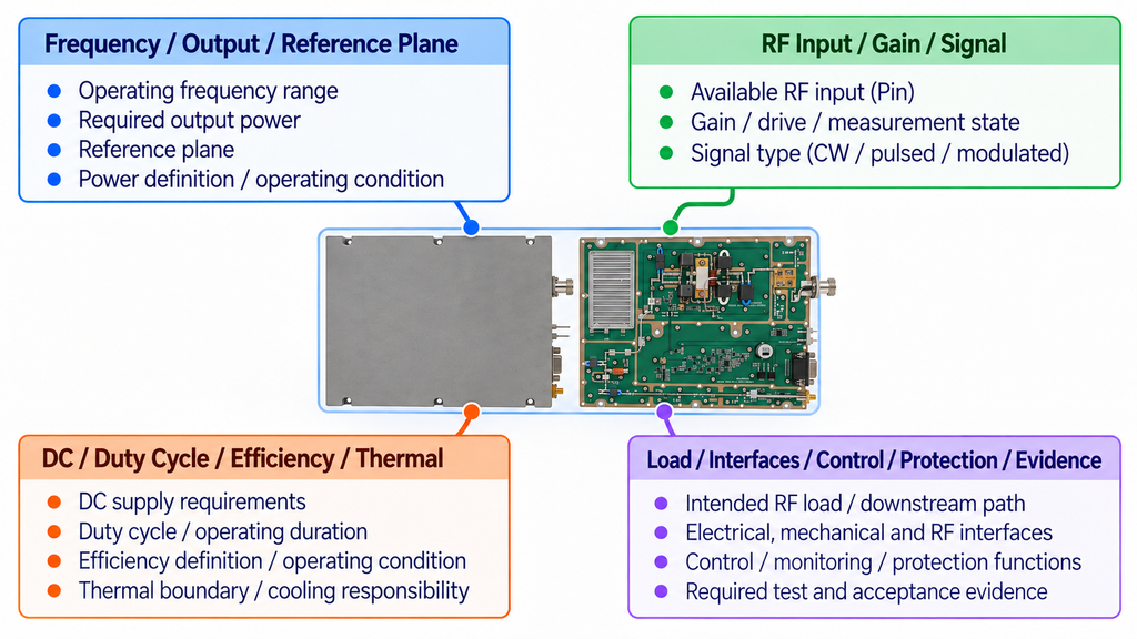
Frequency, output, and reference plane establish where the module must operate, how much RF output is required, how that power is defined, and where Pout applies. A power number without its operating condition and reference plane is incomplete.
Available RF input, gain, and signal establish how the module will be driven. Available Pin must refer to the PA input boundary, while gain depends on drive and measurement state. The difference between small-signal and large-signal RF PA gain matters when interpreting specifications. CW, pulsed, and modulated signals can also impose different requirements.
DC, duty cycle, efficiency, and thermal boundary describe how the module must operate and how the surrounding system must support it. RF amplifier power supply requirements, operating duration, and cooling responsibility must be defined; efficiency is only meaningful with its stated definition and operating condition.
Load, interfaces, control, protection, and evidence complete the minimum product language. The buyer should identify the intended RF load, mechanical and connector constraints, required control or monitoring functions, any protection responsibilities, and the test or acceptance evidence needed for the procurement stage.
These fields provide enough common language to identify missing conditions. They do not determine parameter weighting, target values, or model suitability. Those decisions belong in formal RF PA module selection before RFQ.
6. How Do RF PA Modules Differ Across Products and Applications?
RF PA modules differ because applications impose different frequency, power, waveform, thermal, interface, and packaging requirements.
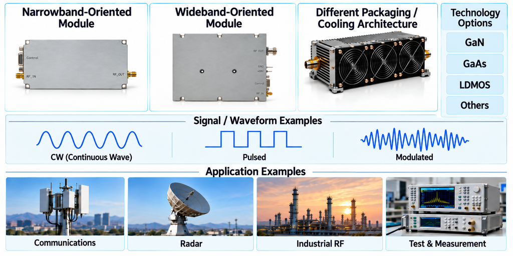
A narrowband module and a wideband module solve different coverage problems. A CW RF power amplifier module, a pulsed or modulated module, and products at different power levels can face different electrical and thermal operating demands.
Semiconductor technologies such as GaN, GaAs, and LDMOS are examples of implementation choices, not standalone proof of project suitability. A technology label does not by itself establish that one complete module is better for a given application.
Cooling architecture, control, protection, connectors, and packaging can likewise vary across communications, radar, industrial RF, test, and other applications. These differences only become meaningful when they are related back to the project’s frequency, output, drive, signal, duty cycle, thermal boundary, load, and interface requirements.
If one PA must cover multiple operating frequencies or a wider continuous band, the next question becomes how to choose wideband RF power amplifier modules for those project conditions. Once the question becomes which architecture, technology, or model is best, this fundamentals article should stop and formal selection should begin.
7. What Should You Define Before Asking for an RF PA Module?
A usable B2B requirement must go beyond “frequency + watts.” Before model comparison or RFQ work, record the known RF, electrical, thermal, mechanical, and evidence requirements, and mark unresolved items explicitly rather than filling them with assumptions.
| Requirement Area | What to Record Before Product Comparison or RFQ |
|---|---|
| Frequency Scope and Operating Points | Define the required operating band, priority frequencies, and any separated or simultaneous operating points that materially affect the RF path. |
| Required RF Output and Reference Plane | State the required Pout, the applicable power definition, and the electrical location where that output must be available. Keep PA-port output separate from downstream or antenna-end power. |
| Available RF Input and Signal | State the available Pin at the defined PA input reference plane, together with signal type, waveform, modulation, and the relevant peak, average, or other power convention. |
| DC Supply and Operating Duration | Record the available DC voltage and material supply constraints, plus CW, pulsed, modulated, duty-cycle, and operating-duration requirements as applicable. |
| Cooling and Thermal Boundary | Define the ambient and thermal conditions, what cooling or thermal interface the project will provide, and which heat-removal responsibilities remain unresolved. |
| RF Load and Downstream Path | Identify the intended RF load and any material filter, switch, connector, cable, feeder, or antenna path between the PA output reference plane and the final load. |
| Interfaces, Control, and Protection | Define size, mounting, RF and DC connectors, control, monitoring, protection, and external-interlock requirements without assuming that any function is built into the module. |
| Test Evidence and Open Items | State the specification, test record, or acceptance evidence required for the procurement stage, and mark unresolved fields explicitly for engineering review instead of assigning silent defaults. |
This starter is not a product-scoring table or final RFQ contract. Its job is to prevent buyers, suppliers, and engineers from using different assumptions for output, input drive, cooling, interfaces, or system responsibility.
Unknowns are acceptable. Silent defaults are not. If the reference plane, available Pin, cooling boundary, protection requirement, or another material field is unresolved, identify it for engineering review.
Once the project record is sufficiently defined, RF PA module selection before RFQ can turn those inputs into formal selection and supplier-communication requirements. The same record can be used as an initial input to an RF SKYPOWER engineering or RFQ review without implying that a specific model is already suitable.
8. What an RF PA Module Does Not Guarantee by Itself
Understanding what an RF PA module is does not prove that a specific module is suitable for a project.
A module name, frequency range, and rated power do not by themselves prove usable RF output with the project’s actual signal and operating state. They also do not establish antenna-end or final-load power because downstream path losses and reference planes remain separate system considerations.
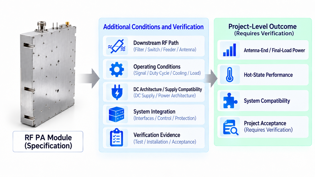
Basic module specifications likewise do not prove sustained hot-state performance, compatibility with the project’s DC architecture, cooling system, controls, or RF path. Mismatch and protection behavior also require product-specific definitions and evidence.
Nor does the module definition establish project acceptance. Suitability requires the relevant product specification, project conditions, engineering review, and any required verification evidence.
Questions about system implementation belong to RF power amplifier integration, while model selection belongs to the formal RF PA selection process. The module definition establishes the product boundary; it does not replace either decision.
Conclusion
An RF power amplifier module is a power-amplification building block within a larger RF system, not automatically a complete amplifier system. It accepts a defined RF input, raises RF power under stated operating conditions, and connects to the surrounding system through product-specific RF, electrical, thermal, mechanical, and sometimes control interfaces.
Understanding that boundary tells a buyer what product layer is being discussed and which responsibilities still need confirmation. It does not prove that a specific module will meet project output, thermal, protection, integration, or acceptance requirements.
The most important mistake to avoid is assuming that module means a self-contained amplifier with complete power supply, cooling, protection, monitoring, and control already included.
Before comparing products, complete the RF PA Module Requirement Starter with the known project conditions and explicitly flag unresolved items for engineering review. That creates the minimum technical input needed to move from basic understanding into selection.
Submit the completed project conditions and unresolved engineering items to RF SKYPOWER for engineering / RFQ review. Buyers still exploring the product family can review RF power amplifier modules; projects requiring wider continuous frequency coverage can also review Wideband RF Power Amplifier ModulesProduct-family coverage and engineering review do not by themselves guarantee project suitability or final acceptance.