










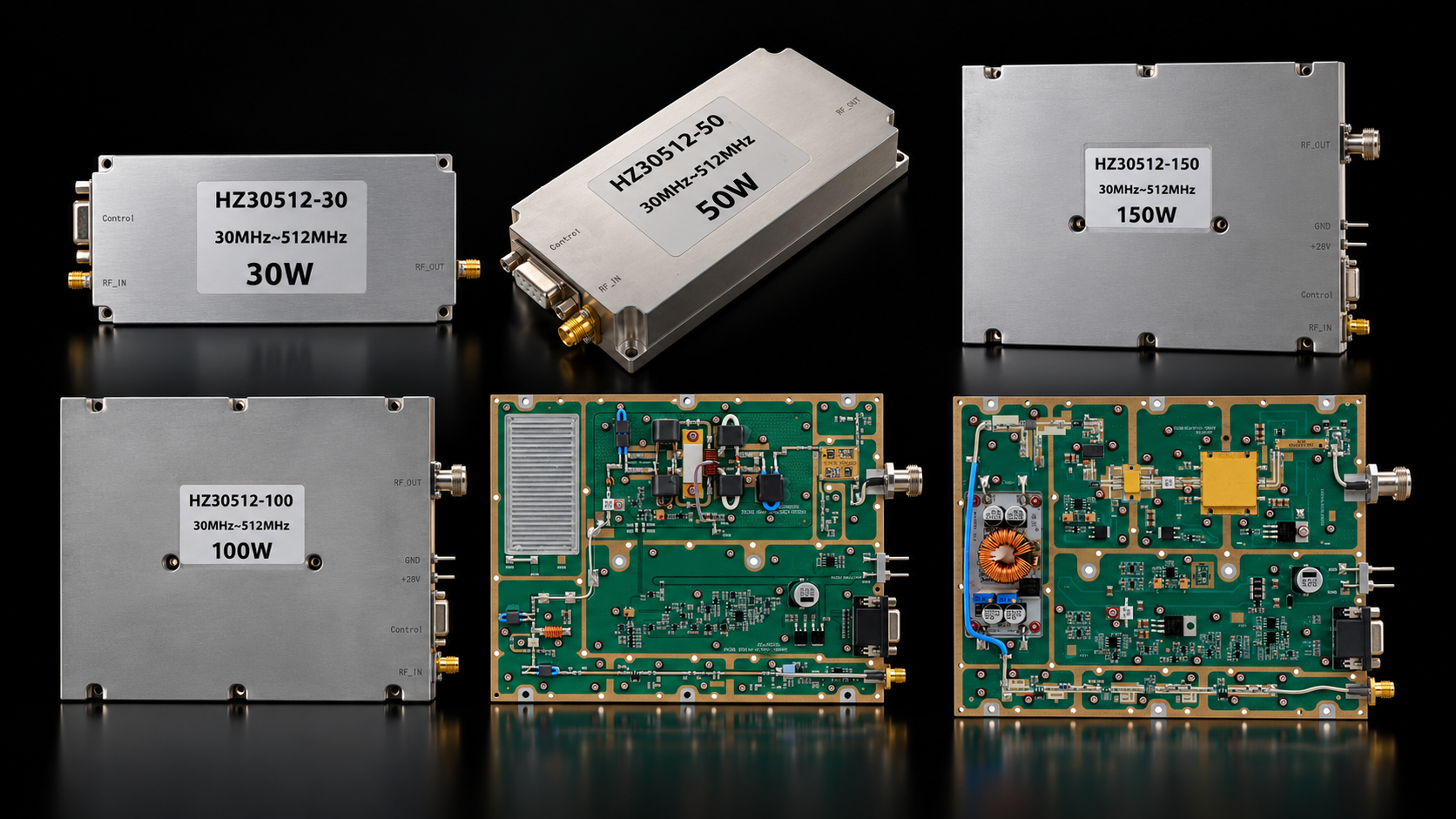
RF SKYPOWER’s 30–512 MHz RF amplifier series includes five standard power classes from 30W to 200W. The important difference across the family is not just output power: the clearest platform transition appears at 100W, where current demand, enclosure size, RF interfaces, and monitoring/protection move to a larger integration level.
Once 30–512 MHz is confirmed as the required frequency range, model selection becomes a practical system question: how much RF output is required, how much DC current and space are available, and which control/protection level fits the equipment?
30–512 MHz Datasheet Quick Access
Select a power class to open its PDF · Swipe on mobile →
1. What Defines the 30–512 MHz RF Power Amplifier Series?
The standard series covers 30 W, 50 W, 100 W, 150 W, and 200 W within the same 30–512 MHz frequency family.
Across these five models, the key shared specifications are:
- 30–512 MHz operating frequency
- Up to 200 MHz maximum instantaneous bandwidth
- 24–32 V operating voltage
- External heatsink required
The 200 MHz value is the maximum instantaneous bandwidth; 30–512 MHz is the operating-frequency range. These are separate specification dimensions.
2. What Actually Changes from 30W to 200W?
The five standard models scale from a compact 30/50 W platform to a larger 100 W+ architecture, with changes in current, dimensions, RF interfaces, and control capability.
30–512 MHz Model / Class Comparison
Click or tap the first column to view each module · Swipe horizontally to compare →
| Module / Class | CW Psat Min / Typ |
Current Typ / Max |
Dimensions / Weight | RF Input / Output |
|---|---|---|---|---|
|
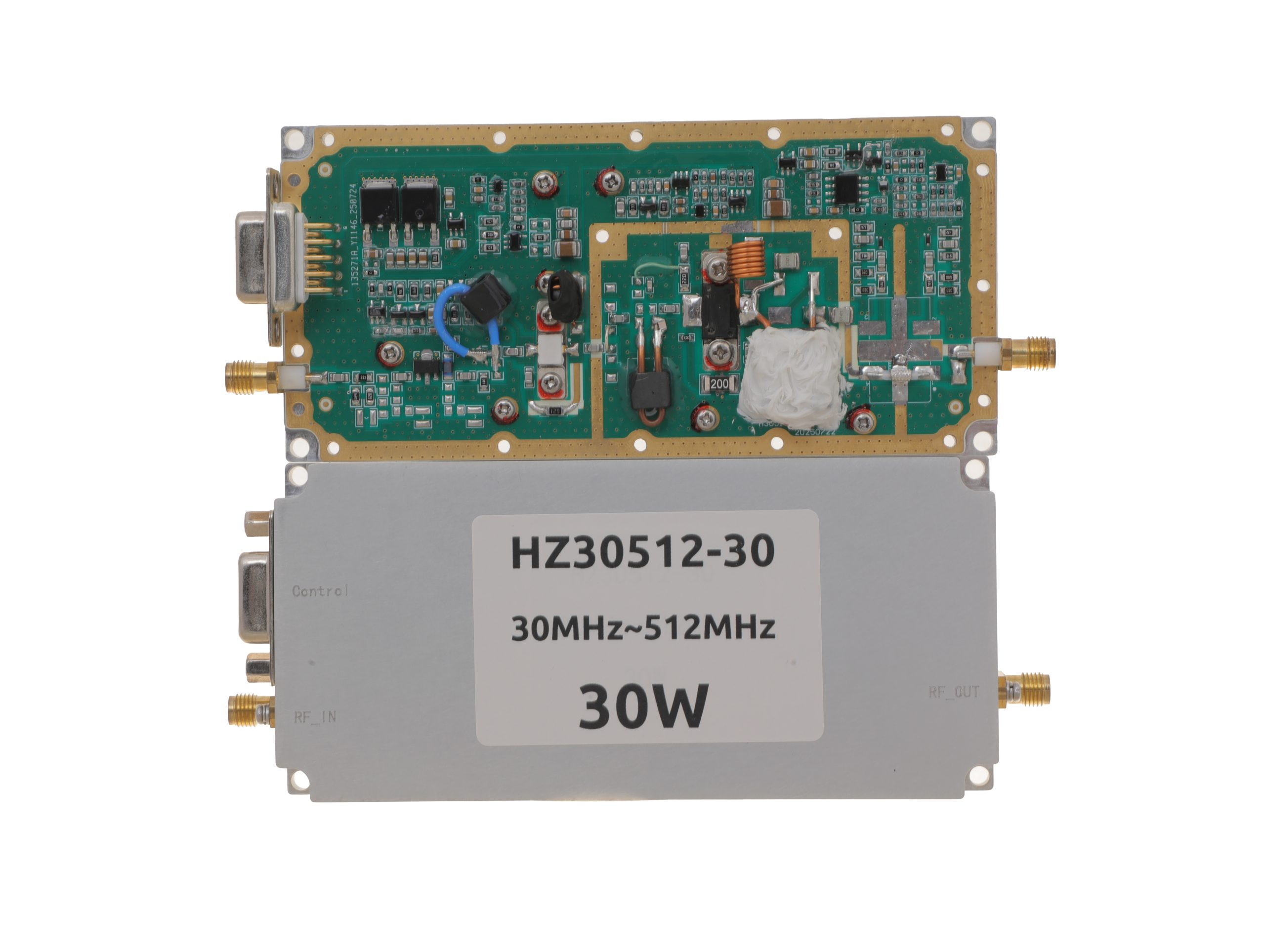
HZ30512-30NA1
30 W class
View module →
|
25 / 30 W | 3.2 / 4 A | 125 × 59 × 21.5 mm | SMA-KFD46 / SMA-KFD46 |
|
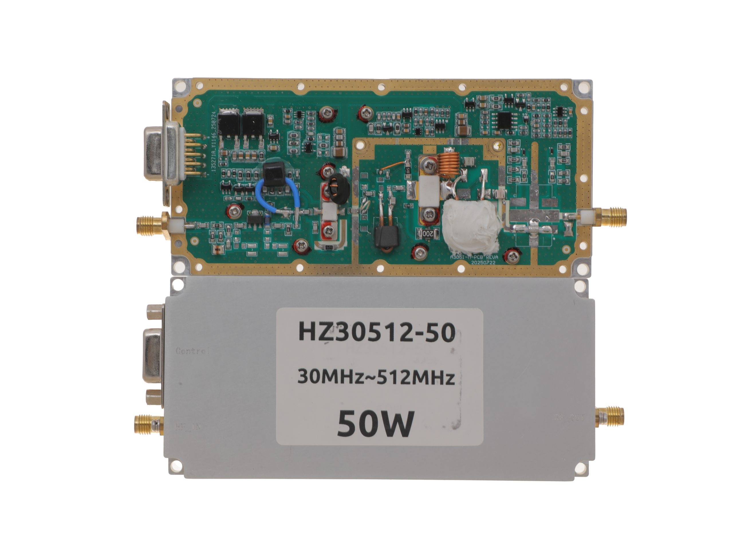
HZ30512-50NA1
50 W class
View module →
|
40 / 50 W | 7.2 / 9 A | 125 × 59 × 21.5 mm | SMA-KFD46 / SMA-KFD46 |
|
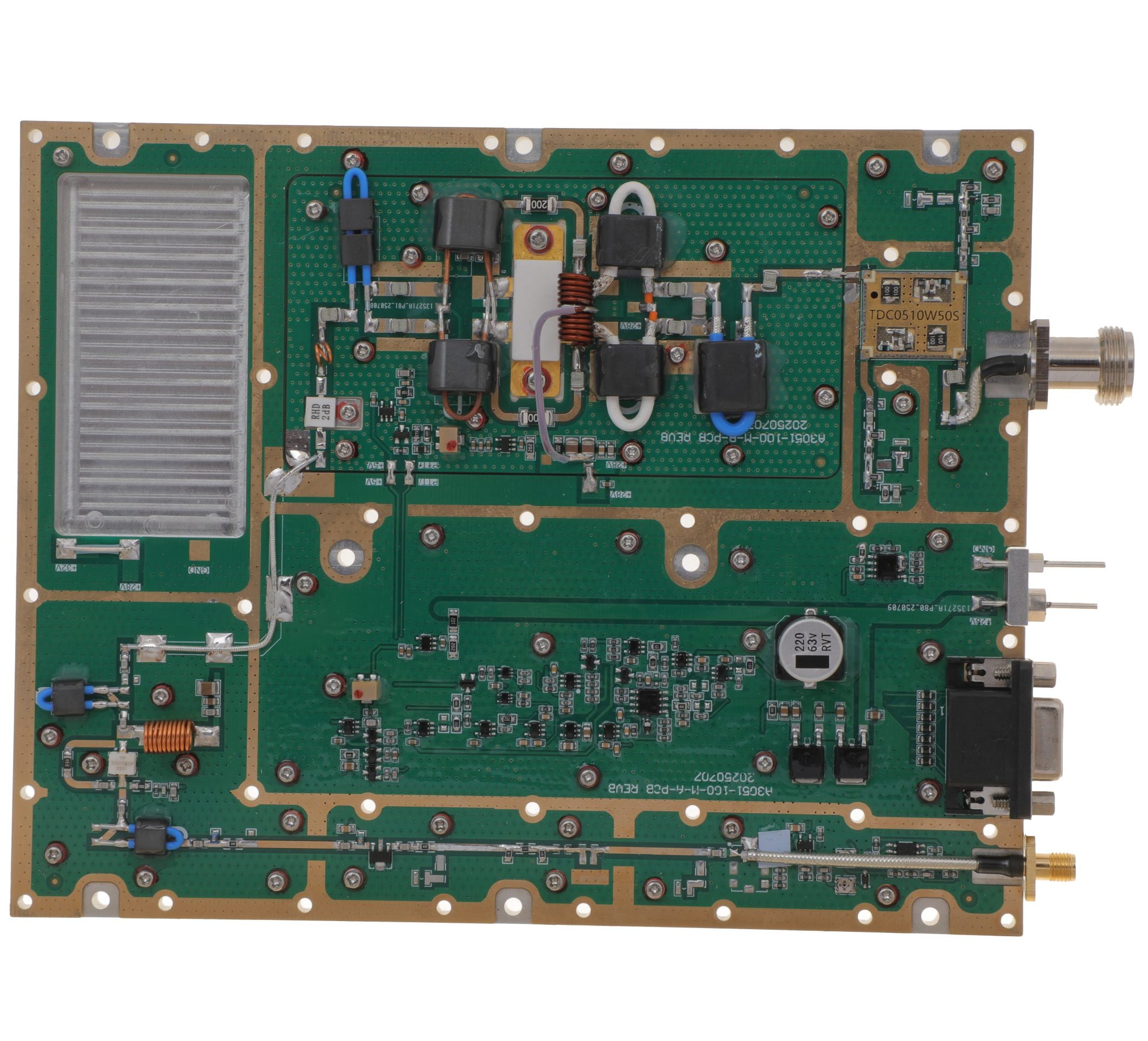
HZ30512-100NA1
100 W class
Architecture transition
|
80 / 100 W | 14.5 / 18 A | 160 × 120 × 25 mm | SMA-F / N-F |
|
HZ30512-150NA1
150 W class
View module →
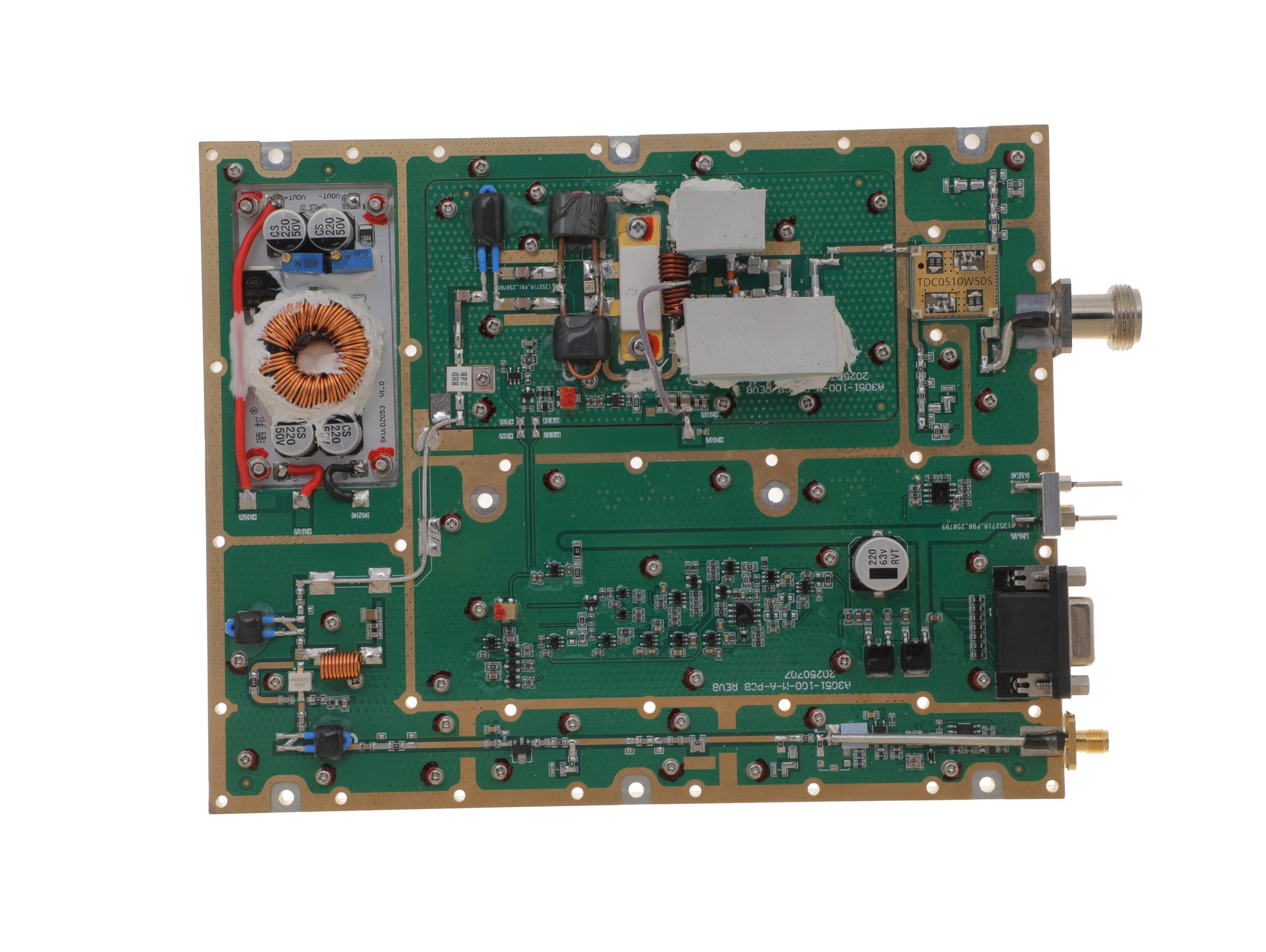
|
120 / 150 W | 16 / 20 A | 200 × 158 × 25 mm | SMA-F / N-F |
|
HZ30512-200NA1
200 W class
View module →
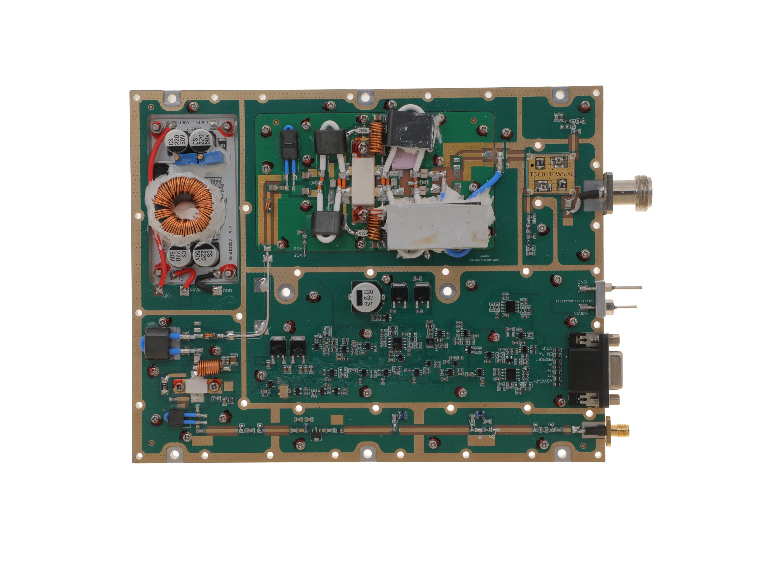
|
160 / 200 W | 29 / 36 A | 200 × 158 × 25 mm | SMA-F / N-F |
The clearest platform transition occurs at 100W. The enclosure grows from 125 × 59 × 21.5 mm to 160 × 120 × 25 mm, while the RF interfaces move from SMA-KFD46 at both ports to SMA-F input and N-F output. Above 100W, the mechanical envelope and current requirement continue to increase, so power class, available DC current, chassis space, and RF cabling should be checked together.
3. How to Interpret Frequency, Bandwidth, Psat, and Gain
Each RF specification should be read together with its operating and measurement condition.
Psat vs Small-Signal Gain
Psat is published under a continuous-wave (CW) condition, while small-signal Gain and Input VSWR are measured with a VNA at -20 dBm. These results describe different measurement conditions and should not be treated as one large-signal performance dataset.
The output reference plane also matters. Pout measured at the amplifier RF output is different from the final power available after cables, filters, switches, or other downstream RF losses.
CW Data vs Broadband Signals
The datasheets list up to 200 MHz instantaneous bandwidth, while Psat is published under CW conditions. For wideband or complex signals, waveform, occupied bandwidth, operating point, and thermal condition should be defined separately.
If the project requires full-power broadband spectral performance or hot-state full-band output, treat those as project-specific evidence requirements rather than extensions of the CW Psat specification.
4. How Control and Protection Change Across the Series
Control capability scales from basic PA_EN and thermal protection on the 30/50 W models to expanded monitoring and protection on the 100 W–200 W family.
30W and 50W: Basic Enable and Thermal Protection
The 30W and 50W models use PA_EN for amplifier enable control together with over-temperature protection. The published shutdown point is 80°C ±5°C, with automatic recovery below 70°C ±5°C.
100W–200W: Expanded Monitoring and Protection
The standard 100W–200W models add alarm reset and expanded status monitoring, including the published Pf, Pr, Tc, TA, and VA signals. The current specifications also list output open/short protection functions where applicable.
Exact thresholds, timing, or control behavior that are not stated in the current datasheet should be confirmed separately.
5. Power, Cooling, RF Interfaces, and Mechanical Integration
All five models operate from 24–32 V, with 28 V as the typical supply value. For integration, check four practical constraints together: available DC voltage/current, chassis space, RF cable arrangement, and cooling.
All five standard models require an external heatsink, so the host system must provide an appropriate thermal path. [RF amplifier thermal management] can then be used for the detailed heatsink, airflow, and hot-state design considerations.
6. What the Datasheets Can—and Cannot—Tell You
The HZ30512 datasheets provide the model-level information needed for initial product selection and system-integration planning.
| The Datasheets Can Support | Additional Evidence Is Needed For |
|---|---|
| Operating frequency and maximum instantaneous bandwidth | Hot-state guaranteed output across the full operating range |
| CW Psat and small-signal gain under their stated test conditions | Maximum-bandwidth full-power spectral performance |
| Input RF power range and small-signal input VSWR | Installed RF-path VSWR or antenna-end power |
| Operating voltage and current | Unpublished efficiency, PAE, or derived thermal dissipation |
| Explicitly listed control and protection functions | Unpublished numeric VSWR trip thresholds or detailed control behavior |
| Published environmental entries | Project-specific environmental suitability |
| Dimensions, weight, and RF connectors | Proof that a specific system installation is suitable |
| External-heatsink requirement | Proof that a particular heatsink or airflow arrangement is sufficient |
| Published model-level specifications | Serial-number-specific acceptance or batch consistency |
For initial product selection, the datasheet is enough to shortlist the appropriate model. Add project-specific evidence only where the final integration or acceptance decision depends on conditions not covered by the published specification.
7. When to Move from Technical Review to Product Selection
Continue to 30–512 MHz Model Review
Open the published datasheet, then send the exact model and integration requirements for RFQ · Swipe on mobile →
Power class still unresolved? Use the 30–512 MHz RF PA selection guide. If the required frequencies extend outside this range, review the wider RF PA module families.
If none of the five standard power classes fits the required Pout or integration envelope, move to an engineering RFQ for the non-standard requirement.
Conclusion
RF SKYPOWER’s 30–512 MHz RF amplifier family covers five standard power classes from 30 W to 200 W, with the 100 W level marking the clearest transition in mechanical format, RF interfaces, current demand, and control architecture.
The right model should be selected around the actual system requirements, including frequency, target Pout, available RF drive, DC supply, mechanical space, cooling conditions, RF interfaces, and control functions.
With these requirements defined, you can move directly to a standard 30–200 W model or submit an RFQ for a custom 10–1000 W configuration.
If your project requires a custom power level, control interface, mechanical format, or other integration conditions, our engineering team can review the requirements with you directly. You can contact RF SKYPOWER to confirm the model, discuss customization, and move the project into technical evaluation.