










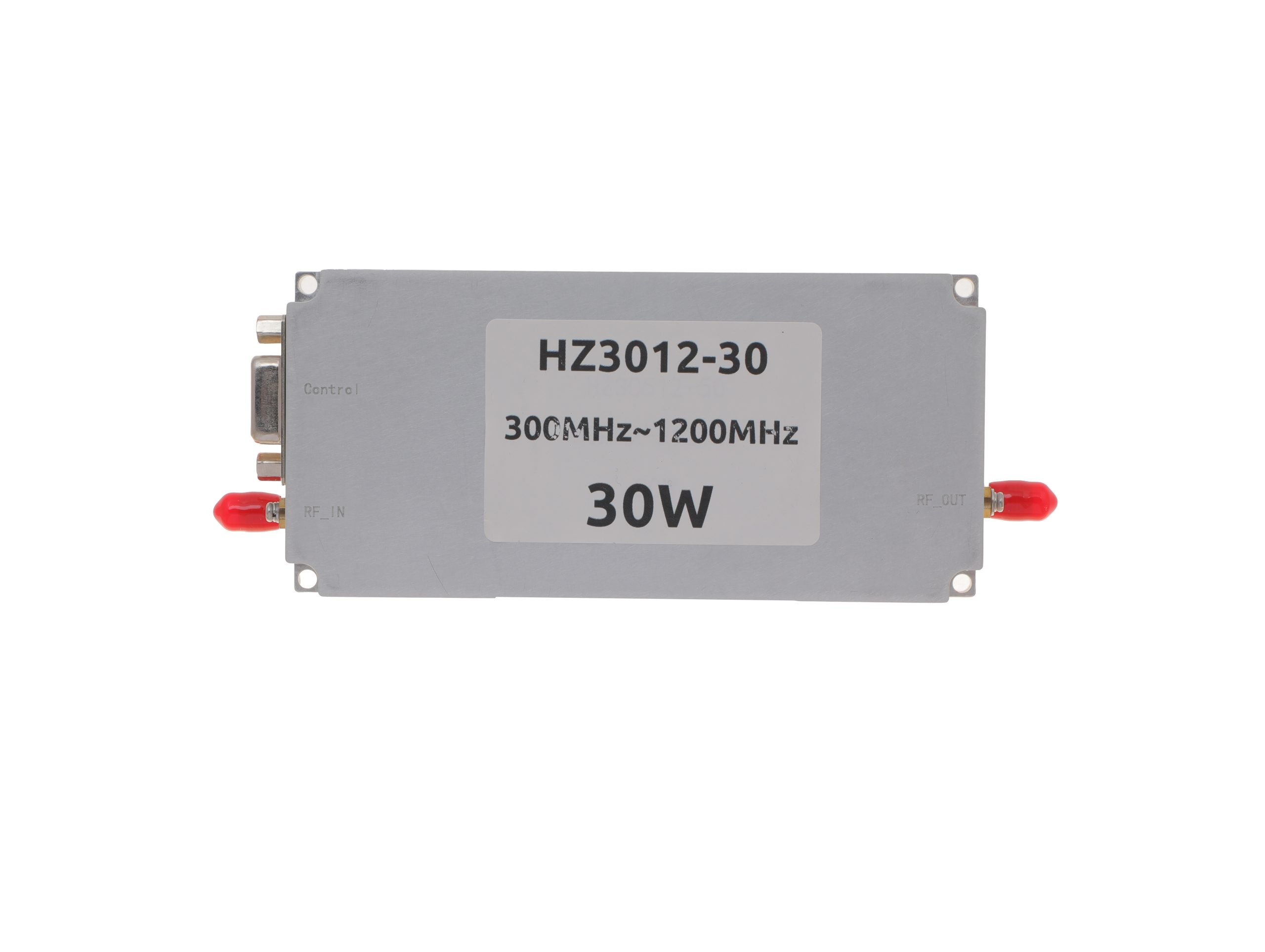
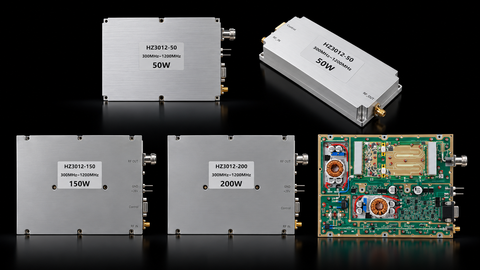
RF SKYPOWER’s 300-1200 MHz RF amplifier family covers UHF frequencies and overlaps the lower edge of the IEEE L-band. This broad frequency coverage is commonly relevant to communication, telemetry, data-link, radar, and other wideband RF systems that need operation across multiple frequencies within one amplifier family.
The standard series covers 30 W, 50 W, 100 W, 150 W, and 200 W. For projects outside these standard power levels, RF SKYPOWER can also evaluate custom 10 W–1000 W configurations around the required frequency, output power, signal condition, mechanical format, RF interfaces, cooling, and control requirements.
The key question is not only how much RF power each model delivers, but how the 300–1200 MHz family changes in hardware platform, DC demand, control architecture, and integration burden as power increases.
1. Why 300–1200 MHz Forms a Distinct Wideband RF PA Family
The HZ3001200 family combines a 300–1200 MHz operating range with up to 200 MHz maximum instantaneous bandwidth.
The five standard base models are:
- HZ3001200-30
- HZ3001200-50
- HZ3001200-100
- HZ3001200-150
- HZ3001200-200
All five also share a 24–32 V operating-voltage range, with 28 V typical, and require an external heatsink.
What makes the family more distinctive is its two-platform structure:
- 30 W / 50 W compact platform
- 100 W / 150 W / 200 W shared high-power platform
The lower-power models use a smaller enclosure with SMA-KFD46 RF input and output. At 100 W, the series moves to a larger common enclosure with SMA-F input, N-F output, and a different control-interface architecture.
In practical terms, this is one RF family built on two hardware platforms.
2. Two Hardware Platforms: 30/50W vs 100/150/200W
The main hardware transition occurs at 100 W.
300–1200 MHz Power-Class and Platform Comparison
Select a model to open its PDF datasheet · Swipe horizontally to compare →
| Model / Power Class | Psat Min / Typ | Current Typ / Max | Dimensions | RF Input / Output | Control Architecture |
|---|---|---|---|---|---|
| HZ3001200-30 30 W class View PDF ↗ | 25 / 30 W | 2.4 / 3 A | 125 × 59 × 21.5 mm | SMA-KFD46 / SMA-KFD46 |
|
| HZ3001200-50 50 W class View PDF ↗ | 40 / 50 W | 5.6 / 7 A | 125 × 59 × 21.5 mm | SMA-KFD46 / SMA-KFD46 |
|
| HZ3001200-100 100 W class View PDF ↗ | 80 / 100 W | 11.5 / 14 A | 200 × 158 × 25 mm | SMA-F / N-F |
|
| HZ3001200-150 150 W class View PDF ↗ | 120 / 150 W | 18 / 22 A | 200 × 158 × 25 mm | SMA-F / N-F |
|
| HZ3001200-200 200 W class View PDF ↗ | 160 / 200 W | 24 / 29 A | 200 × 158 × 25 mm | SMA-F / N-F |
|
The 30 W and 50 W models share a 125 × 59 × 21.5 mm, 0.5 kg format with SMA-KFD46 input/output and a D-Sub 9-pin control interface.
At 100 W, the platform changes to 200 × 158 × 25 mm, 1.4 kg, SMA-F input, N-F output, and a D-Sub 15-pin control interface. The 150 W and 200 W models retain this same physical platform.
That makes 100 W the platform transition point. From 100 W upward, the mechanical envelope remains the same while the required DC current continues to increase.
3. 900 MHz Operating Span vs 200 MHz Instantaneous Bandwidth
Across the 300–1200 MHz family, RF power amplifier instantaneous bandwidth is specified at up to 200 MHz within a 900 MHz operating-frequency span.
These two specifications answer different system questions.
Operating Coverage: 300–1200 MHz
The 300–1200 MHz value defines where the amplifier can operate.
A system may use different operating frequencies across that range without requiring the amplifier to process the entire 900 MHz span as one simultaneous signal.
Simultaneous Signal Bandwidth: Up to 200 MHz
The 200 MHz value defines the maximum published instantaneous bandwidth for broadband signals.
So:
900 MHz operating span ≠ 900 MHz instantaneous signal bandwidth.
This distinction is particularly important when the project uses wideband or multi-carrier signals rather than a narrowband CW source.
Keep CW and Small-Signal Conditions Separate
The datasheets also use different test states for different RF parameters:
- Psat: CW condition
- Small-signal gain: VNA swept-frequency measurement at -20 dBm
- Input VSWR: VNA swept-frequency measurement at -20 dBm
- Instantaneous bandwidth: broadband-signal context
The input level for the VNA measurements is calibrated or measured at the amplifier input.
The output reference plane should also be defined when specifying required Pout. Power at the amplifier RF output is not the same as final power after downstream cables, filters, switches, or other RF-path losses.
For broadband projects, waveform, occupied bandwidth, RF operating point, and thermal condition can be defined together with the required output so that the model is evaluated against the actual signal condition.
4. M1 Optional Control: When the Base Model Is Not Enough
For the 100 W, 150 W, and 200 W platforms, selecting the power class and selecting the control version are separate purchasing decisions.
30W and 50W: Basic Enable and Thermal Protection
The 30 W and 50 W models provide PA_EN control and over-temperature protection.
The published thermal logic shuts the amplifier down above 80°C ±5°C and automatically restores operation after the temperature falls below 70°C ±5°C.
100W–200W: Expanded Base-Model Functions
The 100 W, 150 W, and 200 W base models add:
- PA_EN
- Over-temperature protection
- Output open / short protection
- Alarm Reset
- Pf forward RF power indication
- Pr reverse RF power indication
- Tc temperature analog indication
- TA temperature alarm
- VA open / short alarm
The published RF power amplifier load mismatch protection behavior covers output open/short conditions without defining a general numeric VSWR trip ratio.
Base Models vs M1 Optional Functions
For projects requiring additional control, the corresponding optional versions are:
- HZ3001200-100-M1
- HZ3001200-150-M1
- HZ3001200-200-M1
Control, Monitoring, and M1 Options by Product Group
Base and M1 functions must stay separate · Swipe horizontally to compare →
| Product Group | Basic Control | Protection | Monitoring | M1 Optional Functions | Must Avoid Misunderstanding |
|---|---|---|---|---|---|
| 30 W / 50 W base models Basic enable and thermal-protection platform. Base platform |
|
|
No expanded 100 W+ Pf, Pr, Tc, TA, or VA set is listed in the current datasheets. | Not defined as part of the 100 W+ M1 option structure. | Do not transfer 100 W+ monitoring, open / short protection, or M1 functions to the 30 W / 50 W models. |
| 100 W–200 W base models Expanded monitoring and protection platform. Base model |
|
|
|
[note1] functions are not standard base-model functions. | Do not assign M1 functions to the base models or infer an unpublished numeric VSWR trip threshold. |
| Corresponding 100 W–200 W M1 versions HZ3001200-100-M1, HZ3001200-150-M1, and HZ3001200-200-M1. M1 optional | Base-model control plus the optional functions identified by [note1]. | Base protection plus note-tagged Voltage Alarm / Current Alarm functions where specified. | Base monitoring plus optional control / monitoring functions where noted. |
|
M1 capability does not define undocumented RS485 commands, timing, recovery logic, or protection thresholds. |
For 100 W+, the RF power class and the control path are separate purchasing decisions. Projects that need RF amplifier RS485 control, adjustable gain, attenuator control, or additional M1 functions can specify the power level and control version together during engineering review.
5. Same 100W+ Envelope, Higher DC and Cooling Burden
The 100 W, 150 W, and 200 W models share the same 200 × 158 × 25 mm envelope, while RF amplifier current consumption rises across the three power classes:
- 100 W: 11.5 / 14 A typical / maximum
- 150 W: 18 / 22 A
- 200 W: 24 / 29 A
This is the main integration consequence of the shared 100 W+ platform.
The enclosure and RF connector arrangement remain common, but DC supply capacity and current-path requirements increase with power class, while cooling should be reviewed separately for the 100 W, 150 W, and 200 W configurations.
All five standard models operate from 24–32 V, with 28 V typical. The datasheets also state that output capability and gain vary with operating voltage, so the intended supply condition should be defined with the project.
Every model requires an external heatsink, making RF amplifier thermal management part of the host-system design.The datasheets establish the need for external cooling, but they do not publish a universal thermal resistance, airflow requirement, or hot-state derating curve.
A project that requires a defined heatsink, airflow target, or continuous hot-state operating condition can therefore include those requirements in the engineering review.
6. Use the Model Datasheet as the Published Comparison Baseline
For model-level comparison, the current model datasheet should be used as the published reference for values such as current, dimensions, RF connector type, control options, and RF test conditions.
The information sources serve different purposes:
- Product-family page: product discovery and quick browsing
- Model datasheet: published model-level specifications
- Project or serial-number test report: project-specific or unit-specific verification
| Model datasheet can establish | Project-specific evidence may still be required for |
|---|---|
| Operating frequency and instantaneous bandwidth | Hot-state full-band Pout |
| CW Psat and small-signal VNA parameters | Full-power broadband spectral performance |
| Voltage and operating current | Project-specific efficiency or thermal calculations |
| Dimensions and RF interfaces | Final installation compatibility |
| Base-model and M1 functions | Detailed protocol, timing, or unpublished thresholds |
| External-heatsink requirement | Validation of a specific cooling design |
| Model-level specification | Serial-number acceptance or batch consistency |
This gives buyers a clear comparison hierarchy: use the model datasheet to compare standard products, then define additional project evidence only where the integration or acceptance requirement needs it.
7. Standard 30–200W, M1 Control, or Custom 10–1000W?
Once the frequency, required Pout, RF input, signal condition, DC capability, mechanical constraints, RF interfaces, cooling, and control requirements are defined, there are three product paths.
Standard 30–200 W models are the direct route when one of the published 30 W, 50 W, 100 W, 150 W, or 200 W configurations matches the project requirement.
M1 control versions apply to 100 W, 150 W, and 200 W projects that also require functions such as RS485, gain adjustment, attenuator setting, or the additional voltage/current monitoring options.
For projects outside the standard configurations, custom RF amplifier engineering is available from 10 W to 1000 W around the required output power and integration conditions. The 10 W–1000 W range is a custom engineering capability, not a statement that every frequency, power, interface, and mechanical combination exists as a standard model.
Continue to 300–1200 MHz Product Review
Choose a power class, open its datasheet or product page, then contact us for customization · Swipe horizontally →


The 300–1200 MHz RF power amplifier series can be used for standard model and datasheet review, If the frequency range or required power class is still being defined, compare operating frequency, target Pout, available RF drive, duty cycle, and cooling requirements first; our wideband RF power amplifier selection guide covers this decision in detail.
Conclusion
RF SKYPOWER’s 300–1200 MHz RF amplifier family spans UHF into the lower L-band and combines five standard 30–200 W power classes with a custom 10 W–1000 W engineering path.
The standard series is built around two hardware platforms: compact 30 W / 50 W models and a shared 100 W / 150 W / 200 W platform. Within the 100 W+ group, the same enclosure supports progressively higher DC current requirements, while M1 adds a separate control-version choice.
For model selection, define the operating frequency, Pout and output reference plane, RF input, signal bandwidth, DC capability, cooling, RF interfaces, mechanical requirements, and control path.
If a standard model matches those requirements, we can move directly into model and datasheet confirmation. If the project requires M1 functions or falls outside the standard 30–200 W configurations, our engineering team can review the control or custom 10 W–1000 W path with you directly.
Contact RF SKYPOWER with the project frequency, Pout, RF input, signal condition, DC, cooling, mechanical, RF-interface, and control requirements so we can confirm the appropriate technical path.