










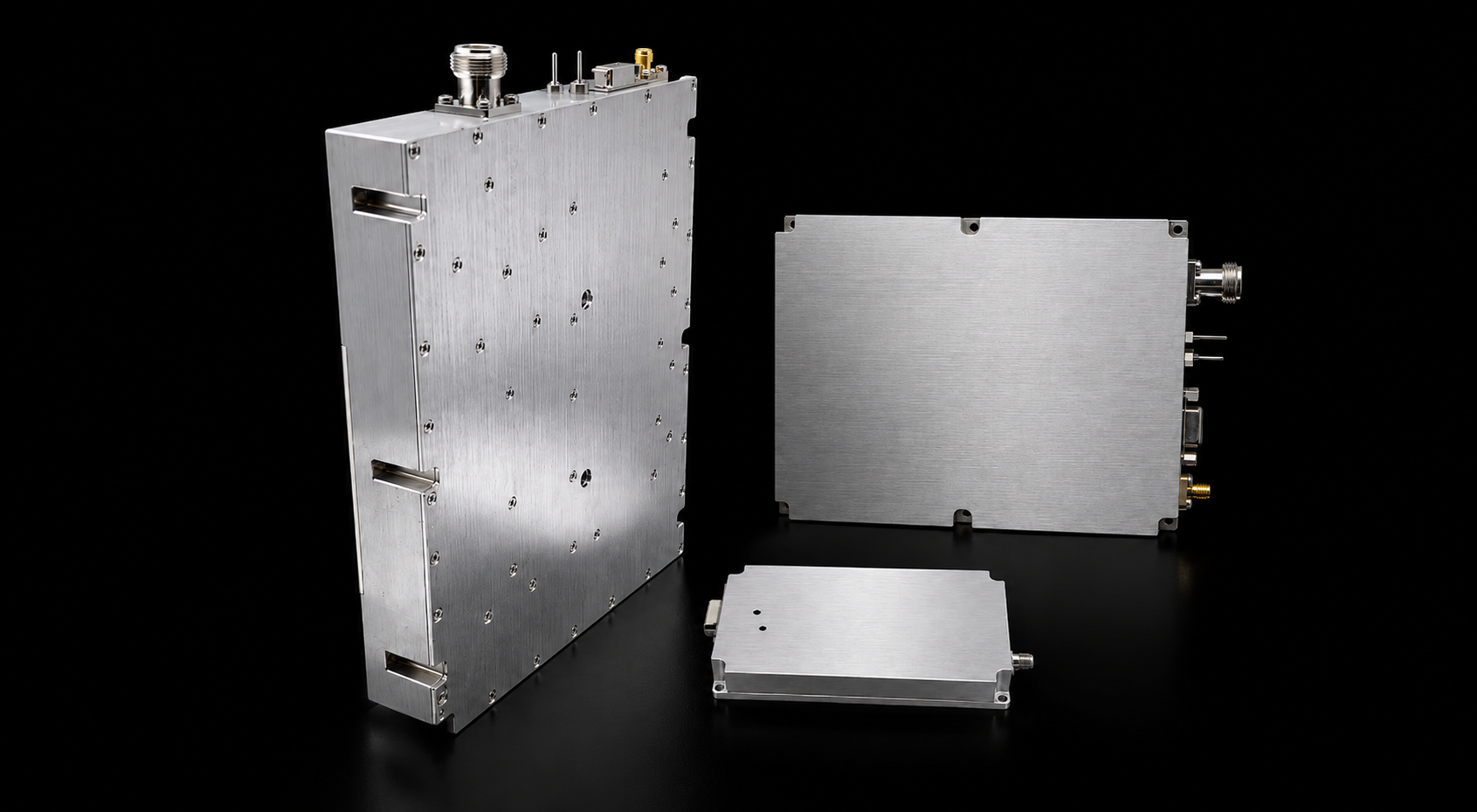
Choosing wideband RF power amplifier modules involves more than matching a frequency label with a nominal wattage.
Two modules may cover the same required frequencies but differ in RF input requirements, output margin, gain variation, thermal behavior, or integration conditions. The result may also change depending on whether the required power is defined at the PA output connector or at the antenna input.
A practical selection begins with six project boundaries:
- required operating frequencies;
- target RF output and its reference plane;
- available RF input power;
- 28 V supply condition;
- duty cycle and cooling method;
- downstream RF-path conditions.
The product families and datasheets on this page provide an initial comparison. Final model selection should then reflect the frequencies and operating conditions that matter to the project.
Before comparing individual modules, answer one question:
Which frequency range and power class are closest to the real operating requirement, and which conditions still need engineering confirmation?
1. Define the Frequency Range and Output Requirement
The first step is to identify the frequencies the system will actually use.
A project may require:
- one continuous operating band;
- several priority frequencies inside a wider range;
- separate operating windows;
- one project-critical band-edge point;
- additional frequency coverage for later system changes.
The module does not always need to cover every frequency between the lowest and highest point. One wideband PA may simplify some architectures, while narrower modules or a mixed arrangement may be more appropriate for others.
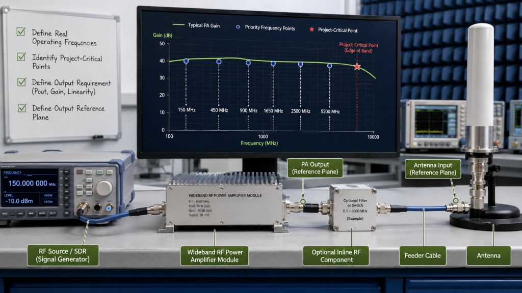
Start With the Required Frequency Points
When the frequency plan is already defined, record:
- the lowest required frequency;
- the highest required frequency;
- priority operating points;
- any point close to a band edge;
- frequency points with different output targets.
These points should guide the module-family comparison more than the overall catalog range.
For example, a project that uses frequencies only below 1200 MHz may not benefit from a 300–2700 MHz module simply because the wider range is available. A wider series becomes relevant when the additional coverage supports a real system requirement.
Choose an Initial Power Class
The listed 30 W, 50 W, 100 W, 150 W, and 200 W options provide initial power-class choices.
The suitable class depends on:
- required PA-port output;
- available RF input power;
- operating frequency;
- duty cycle;
- cooling condition;
- downstream RF-path loss;
- required operating margin.
When the final power class is uncertain, begin with the approximate output target and define whether it applies at the PA output connector or farther along the RF path.
Define the Output Reference Plane
An output requirement is incomplete unless its measurement location is stated.
The target may refer to:
- the PA output connector;
- the output of a filter or RF switch;
- the end of a feeder cable;
- the antenna input.
These locations may have different power levels because filters, switches, couplers, connectors, and cables introduce loss.
For initial module comparison, it is normally useful to define the PA-port output first and treat the downstream RF path as a separate system boundary.
2. Compare Wideband RF PA Frequency Families
The frequency families below address different operating ranges and integration boundaries.
Begin with the project’s required frequency points, then compare the relevant datasheet conditions with the target PA-port output, available RF input power, 28 V supply, duty cycle, and cooling method.
The complete wideband RF power amplifier module range can be used as a broader product reference while the individual tables below provide direct access to each power-class datasheet.
30–512 MHz RF Power Amplifier Modules
The 30–512 MHz family covers frequencies from VHF through the lower UHF region within one module series.
It may be relevant when several required points are distributed across this lower-frequency range and one PA platform is preferred. Selection should still be based on the actual operating points, required output, and available RF input rather than the lower frequency limit alone.
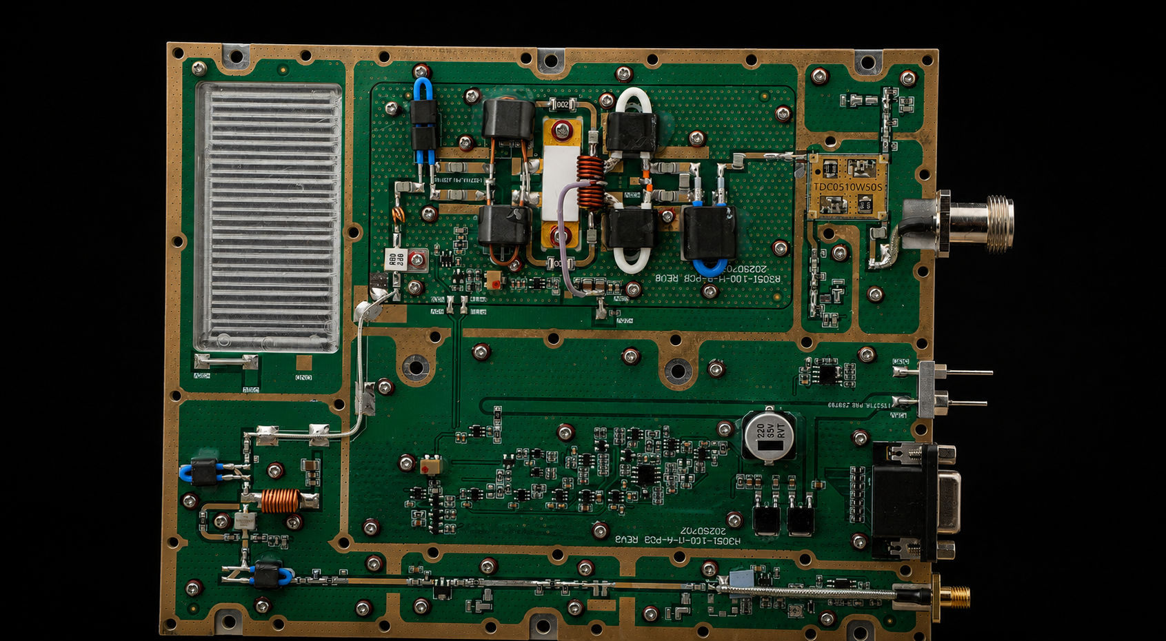
30-512MHz RF Power Amplifier Modules
Low-frequency RF PA modules for VHF/UHF wideband amplification, system integration, and project-specific RF test platforms.
| Output Power | Module Type | Datasheet |
|---|---|---|
| 30W | Wideband RF PA module | Download 30W Datasheet |
| 50W | Wideband RF PA module | Download 50W Datasheet |
| 100W | Wideband RF PA module | Download 100W Datasheet |
| 150W | Wideband RF PA module | Download 150W Datasheet |
| 200W | Wideband RF PA module | Download 200W Datasheet |
300–1200 MHz RF Power Amplifier Modules
The 300–1200 MHz family provides a focused starting point when no project frequency is required above 1200 MHz.
The selected power class should then be compared with the required PA-port output, available input drive, duty cycle, and cooling condition. A wider family becomes relevant only when the additional upper-frequency coverage serves a defined project need.
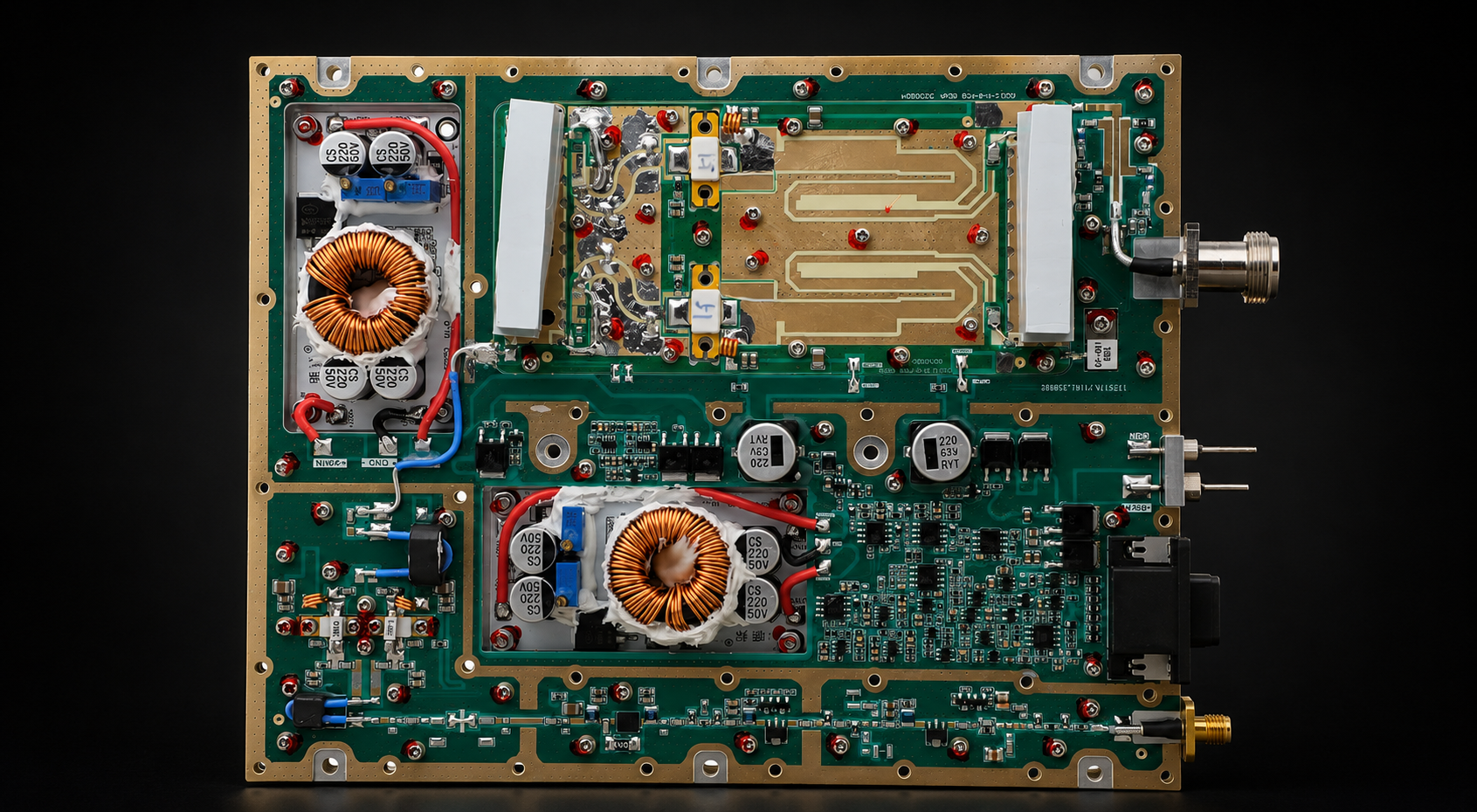
300-1200MHz RF Power Amplifier Modules
Broad RF PA coverage for communication, telemetry, and RF subsystem integration where a wider low-band module is preferred.
| Output Power | Module Type | Datasheet |
|---|---|---|
| 30W | Wideband RF PA module | Download 30W Datasheet |
| 50W | Wideband RF PA module | Download 50W Datasheet |
| 100W | Wideband RF PA module | Download 100W Datasheet |
| 150W | Wideband RF PA module | Download 150W Datasheet |
| 200W | Wideband RF PA module | Download 200W Datasheet |
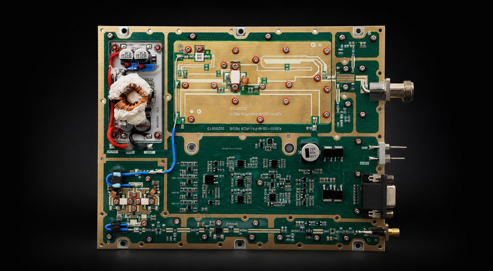
300–1700 MHz RF Power Amplifier Modules
The 300–1700 MHz family extends the upper operating boundary while retaining coverage from 300 MHz.
It becomes relevant when the project includes operating points above 1200 MHz but still requires lower-frequency coverage in the same PA platform. When frequencies are distributed across the range, output, gain, input-drive, and thermal behavior should be compared at the points that matter most.
300-1700MHz RF Power Amplifier Modules
Wideband RF PA modules for multi-band integration across lower cellular, telemetry, and RF testing applications.
| Output Power | Module Type | Datasheet |
|---|---|---|
| 30W | Wideband RF PA module | Download 30W Datasheet |
| 50W | Wideband RF PA module | Download 50W Datasheet |
| 100W | Wideband RF PA module | Download 100W Datasheet |
| 150W | Wideband RF PA module | Download 150W Datasheet |
| 200W | Wideband RF PA module | Download 200W Datasheet |
300–2700 MHz RF Power Amplifier Modules
The 300–2700 MHz family provides broad lower-to-mid-band coverage within one module series.
It may reduce module count when several required frequencies must share one PA platform. Because of the wider span, project-critical frequency points should guide the comparison rather than one center-frequency result or the overall catalog range alone.
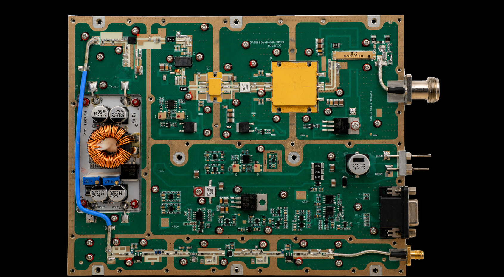
2000–6000 MHz RF Power Amplifier Modules
The 2000–6000 MHz family covers upper-frequency requirements within one standard wideband range.
When a priority point is close to either edge of the range, available output and operating margin should be reviewed at that frequency. A center-frequency result may not represent the same input-drive, output, or thermal condition across every required point.
2000-6000MHz RF Power Amplifier Modules
High-frequency RF PA modules for upper-band RF systems, band-specific projects, and custom frequency requirements within 2-6GHz.
Band-specific and custom RF PA module requirements can be reviewed from this series by project frequency, output power, thermal condition, and test-report needs.
| Output Power | Module Type | Datasheet |
|---|---|---|
| 30W | Wideband / band-specific RF PA module | Download 30W Datasheet |
| 50W | Wideband / band-specific RF PA module | Download 50W Datasheet |
| 100W | Wideband / band-specific RF PA module | Download 100W Datasheet |
| 150W | Wideband / band-specific RF PA module | Download 150W Datasheet |
| 200W | Wideband / band-specific RF PA module | Download 200W Datasheet |
Use the Datasheets for Initial Comparison
The product tables provide direct access to the available power-class datasheets.
A datasheet may show:
- listed frequency range;
- nominal output class;
- gain information;
- DC supply requirements;
- mechanical dimensions;
- connector and control details;
- stated test conditions.
It may also use typical values, selected frequency points, or one defined operating condition.
When a document is close to the project requirement but leaves some conditions unclear, note:
- the module or datasheet name;
- the stated test condition;
- the required frequency points;
- the conditions that still need confirmation.
This separates an initial product match from the engineering questions that remain before final selection.
Custom RF PA Module Options
If standard RF PA modules do not match the required frequency, output power, voltage, cooling, connector, or control interface, RF SKYPOWER can review a custom RF PA module configuration before RFQ.
| Custom Item | Available Range / RFQ Detail |
|---|---|
| Frequency Range | Custom frequency coverage from 20MHz to 20GHz, based on target frequency points and band-edge requirements. |
| Output Power | Project-defined RF output from 10W to 1000W, depending on frequency, duty cycle, cooling, and system integration conditions. |
| Engineering Review | Confirm voltage, gain, input drive, connector, heatsink or forced-air cooling, VSWR protection, control interface, and test-report requirements before RFQ. |
3. Compare the Conditions That Affect Module Selection
After identifying a likely frequency family and power class, compare the conditions that affect system integration.
Module Selection Comparison
| Selection Item | What May Already Be Defined | What Still Needs Engineering Confirmation |
|---|---|---|
| Frequency | Required band or priority points | Matching standard range and project-critical points |
| Output power | Approximate wattage or PA-port target | Required power class and operating margin |
| RF input | SDR, signal-source, or driver output | Actual Pin available at the PA input connector |
| DC supply | Available 28 V system | PA-terminal voltage and current under load |
| Duty cycle | Intermittent or continuous operation | Thermal and cooling boundary |
| Cooling | Fan, cold plate, heat sink, or cabinet airflow | Required thermal interface and operating condition |
| RF path | Filter, switch, cable, connector, or antenna path | PA-port versus antenna-end output requirement |
| Control | Required system interface | Standard or project-defined control boundary |
| Test documents | Datasheet, curve, or report requirement | Required test and reporting scope |
Frequency and Output Target
The selected range should include the required operating points, not merely the lowest and highest values on the project outline.
A wider module may be useful when several frequencies must share one PA platform, the frequency plan may expand, or reducing module count is important.
A narrower range may be more suitable when one fixed band dominates the requirement.
A detailed broadband versus narrowband RF PA comparison can help clarify that architectural choice.
The output requirement should also state whether it applies at the PA connector or after the downstream RF path.
RF Input and 28 V Supply
The available RF input power affects whether the selected PA can reach the required output with adequate margin.
The source setting alone may not show the actual Pin at the PA input connector. Input cables, connectors, filters, switches, splitters, or other components may introduce frequency-dependent loss.
The DC review should consider the available voltage and current, DC cable length, distribution loss, PA-terminal voltage under load, and whether several modules share one supply.
These conditions determine whether the selected module can operate inside the intended 28 V system boundary.
Duty Cycle, Cooling, and RF Path
Intermittent and continuous operation may create different thermal requirements.
The cooling review should reflect the actual heat sink, cold plate, airflow, ambient condition, and installation arrangement.
The downstream RF path should be treated separately from the PA module itself. Filters, RF switches, couplers, feeder cables, connectors, and antennas may change the difference between PA-port output and antenna-end output.
4. Define the Information Needed for Model Confirmation
Not every parameter must be finalized during the first comparison.
The confirmed requirements can be separated from project-defined items so the closest standard option can be identified while the remaining system boundaries are clarified.

Initial Selection Information
Useful starting information includes:
- required frequency range;
- priority or project-critical points;
- approximate RF output target;
- PA-port or antenna-end reference plane;
- available RF input power;
- 28 V supply condition;
- expected duty cycle;
- cooling method;
- mechanical or installation limits;
- known RF-path components;
- control-interface requirements;
- expected test or reporting scope.
A defined frequency range and approximate output target are sufficient for an initial technical review. Additional details can be added as the project boundary becomes clearer.
When Wider-Band Evidence Becomes Relevant
Full test evidence is not required during the initial model comparison.
Once a likely module family has been identified, swept data and detailed measurements at project-critical points may be used to confirm the output, input-drive, DC, thermal, load, and protection boundaries.
A full-band sweep shows the overall response and helps identify unexpected weak regions. Defined critical-point measurements provide the detailed operating evidence needed at the frequencies used by the project.
What a Broadband RF Power Amplifier Must Prove Across the Band explains the difference between catalog coverage and project-level verification.
5. Decide Between a Standard Module and a Custom Review
A standard module is the natural starting point when:
- the required frequencies fit one listed range;
- a listed power class is close to the output target;
- the RF input and 28 V supply are compatible;
- the mechanical and cooling conditions are suitable;
- the standard interface and reporting scope are acceptable.
A custom feasibility review becomes relevant when the project includes:
- a non-standard frequency range;
- separate operating windows;
- an output target outside the listed classes;
- a project-defined mechanical envelope;
- a different connector or control requirement;
- special thermal or environmental conditions;
- additional testing or reporting requirements.
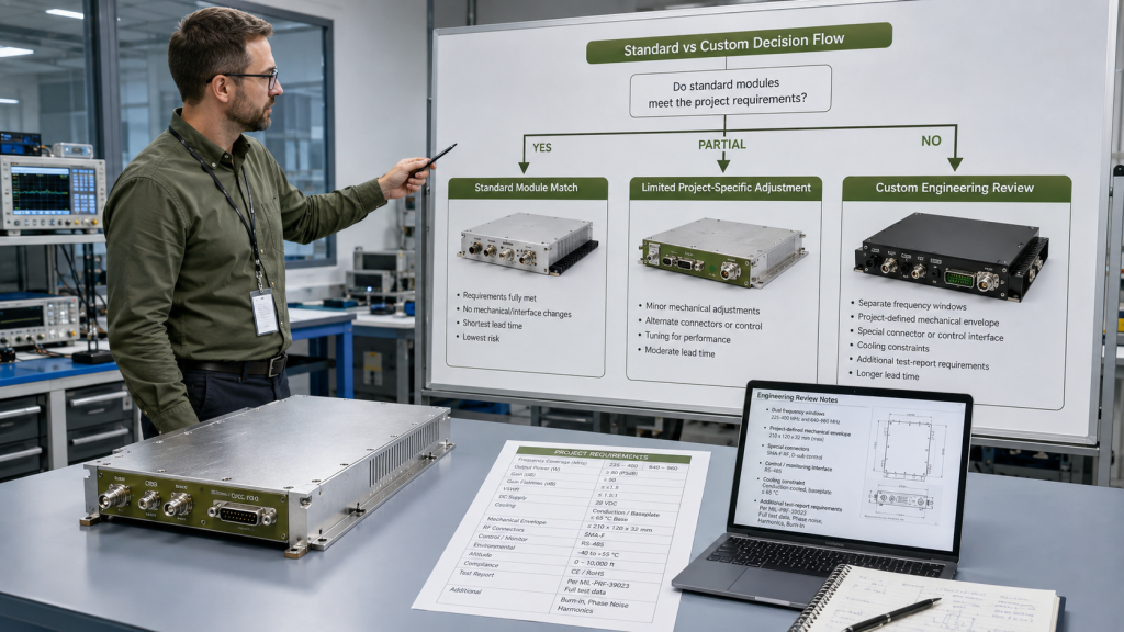
The comparison should determine whether the requirement can use an existing standard module, needs a limited project-specific adjustment, or requires a custom feasibility review.
These items do not all need to be finalized during the first comparison. They can remain project-defined until the relevant technical boundary is clear.
A dedicated RF PA frequency-range selection review is useful when several frequency windows do not clearly match one listed family.
An RF PA power-margin review can help connect PA-port output, downstream path loss, and antenna-end requirements.
FAQ
How Do I Choose the Closest Wideband RF PA Module Family?
Start with the required frequency range and priority operating points.
Select the family that covers those points, then compare the available power classes against the project’s input, output, DC, and thermal boundaries.
Can Model Selection Begin Before Every Parameter Is Finalized?
Yes.
Begin with the confirmed frequency points, approximate output target, available RF input power, supply condition, duty cycle, and cooling method. Undecided items can remain project-defined until the relevant system boundary is clarified.
When Does a Project Need a Custom RF PA Review?
A custom feasibility review becomes relevant when the required frequency range, output target, mechanical boundary, interface, thermal condition, or reporting scope does not align clearly with a listed standard option.
The review can then determine whether an existing option, limited adjustment, or deeper custom design is appropriate.
Conclusion
The product tables on this page provide a direct comparison of the available frequency families and power classes.
The corresponding datasheets support the initial module comparison, but the final choice should also reflect:
- the required operating points;
- output reference plane;
- available RF input power;
- 28 V supply condition;
- duty cycle;
- cooling method;
- downstream RF path.
A standard module may be appropriate when these conditions align with a listed series. Requirements outside the standard frequency, output, mechanical, interface, thermal, or reporting boundaries may need a custom feasibility review.
To begin model confirmation, send RF SKYPOWER the required frequency range or priority points, approximate PA-port or antenna-end output target, and available RF input power. Supply, duty-cycle, cooling, RF-path, control, and reporting conditions can be added as they are defined. The review can then identify the closest standard module family, suitable power class, or need for a custom feasibility review.
Before requesting a quotation, confirm the RF PA selection conditions that determine whether the module will fit the real system, including signal type, output reference plane, DC supply, cooling, RF path, control, and test evidence.