










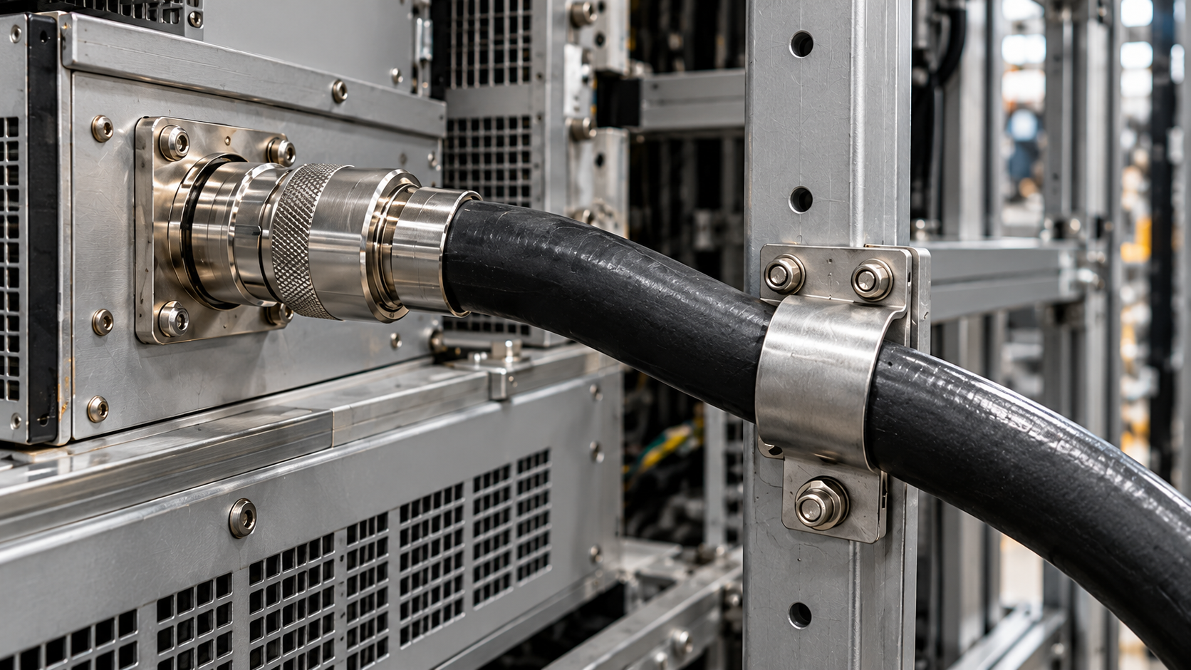
For an RF PA, output port strain relief is acceptable only when the complete port assembly has an approved mechanical load basis, the installed cable and support arrangement conform to it, and the required RF checks pass. A protective boot, cable clamp, or acceptable VSWR reading cannot replace that evidence.
Before signing off, trace where the cable’s weight and service loads go. That determines which parts of the installation need inspection and what evidence supports the acceptance decision.
1. What Mechanical Loads Reach an RF PA Output Port?
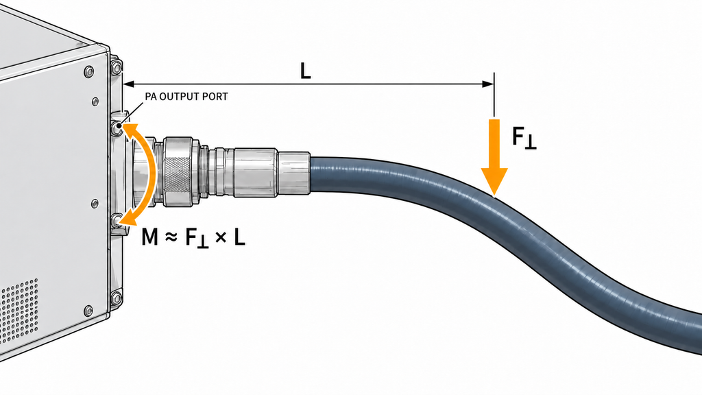
An RF cable can exert more than a straight pull on the PA output connector. Cable weight, stiffness, routing, adapters, and movement around the installation can produce axial tension, lateral force, bending moment, and torsion.
A stiff feeder may pull sideways on an otherwise properly mated connector. An adapter stack can extend the effective moment arm, allowing the same cable force to impose a greater bending moment on the port.
For a single transverse force applied at a known offset, the relationship M ≈ F⊥ × L illustrates this effect:
- M is the bending moment at the PA port.
- F⊥ is the transverse force.
- L is the effective moment arm.
This simplified relationship does not determine an allowable load. Actual installations may involve distributed cable weight, constrained bends, multiple supports, and movement during service.
The port’s construction also matters. A bulkhead connector secured to the enclosure, a connector mounted on a PCB, and an interface connected through an internal coaxial transition can transfer loads into different structures.
The relevant mechanical limit must therefore apply to the complete installed port assembly, including its mounting and internal connections. A connector datasheet alone may not establish what the assembled PA output port can withstand.
Consider the service conditions as well. Opening a hinged panel may pull a cable that hangs freely when the door is closed. Vibration can repeatedly load a suspended feeder. Thermal movement can change tension between fixed attachment points.
These conditions belong in the mechanical assessment whenever they are relevant to the installation.
2. Where Should RF Cable Strain Relief Transfer the Load?
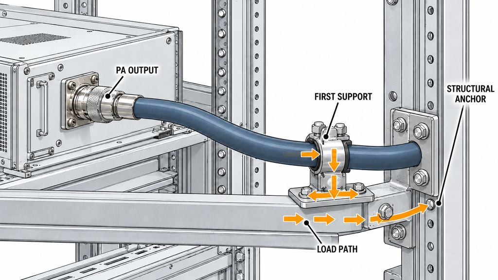
In a support-controlled installation, the restraint transfers cable weight and expected service forces into an approved bracket, frame, or other load-bearing structure.
The cable section between that support and the PA output port must remain within the approved geometry, without imposing an unqualified pulling or twisting load on the connector.
Even with a nearby support, some load may remain at the port. The complete supported arrangement must be qualified, or its residual port loading must be shown to meet the applicable limits.
A clamp mounted on a flexible cover may move with the cover. An insufficiently stiff bracket may deflect under cable weight. Either arrangement can shift the bending load toward the connector rather than relieve it. Excessive clamp pressure can also deform the coaxial cable.
A molded strain-relief boot may reduce flexing at the connector-to-cable transition. Cabinet-level load support still depends on the restraint and the structure carrying it.
Compliance with the cable manufacturer’s bend-radius limit helps control RF cable bending loss, but it does not qualify the mechanical load on an unsupported PA output port.
Some designs intentionally allow the output port to carry a specified mechanical load. Such arrangements require allowable-load data or qualification for the complete PA-side interface, together with evidence that the installed loads remain within that limit.
The two arrangements therefore need different supporting evidence: conformity to a qualified support configuration, or a verified comparison between applied loads and the complete port assembly’s approved limits.
3. Which Mechanical Limits Must Be Defined Before Inspection?
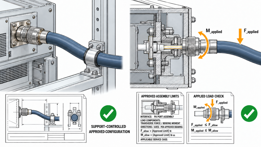
Before inspection, obtain the relevant RF power amplifier module specifications and mechanical drawings, then identify the approved support layout or port-load qualification that applies to the installed assembly.
For a support-controlled design, this may be a released assembly drawing with a qualified cable route, restraint position, mounting arrangement, and permitted variations.
For a port-load-rated design, the engineering basis must define the allowable loading at the complete PA-side interface and assess the forces and moments imposed by the installed cable.
In either case, identify the PA model, output-port construction, connector and adapter types, cable assembly, mounting hardware, and support arrangement.
The applicable load cases may include:
- Cable dead weight and installation handling.
- Access-panel movement.
- Transportation or operational vibration.
- Thermal movement between attachment points.
These are potential load cases, not a universal test list. The project must determine which ones apply.
For a port-load-rated arrangement, the allowable force and moment directions must be defined at a specified interface. The applied-load assessment needs to use corresponding directions and service conditions.
For a support-controlled arrangement, the released geometry and anchor requirements must be specific enough for an inspector to compare the installed assembly with the approved configuration.
Record the governing document number and revision. A qualification performed with another cable, adapter stack, or support position may not cover the current installation.
Connector mating torque, panel-retention torque, and cable torsion also require separate treatment. Mating torque controls the coupling interface. Panel-retention torque applies to the mounting hardware. Cable torsion is a mechanical load that may arise during assembly or service.
A mating-torque specification cannot establish the allowable bending moment or side load at the PA port.
No universal allowable side load, support spacing, or bending-moment limit applies to every RF PA installation. When the required engineering basis is missing, hold acceptance and request the relevant design or qualification evidence.
If RF PA vibration testing is part of the acceptance evidence, confirm that the tested cable assembly, restraints, and PA mounting match the final installed configuration.
4. How to Inspect Strain Relief in the Final PA Installation
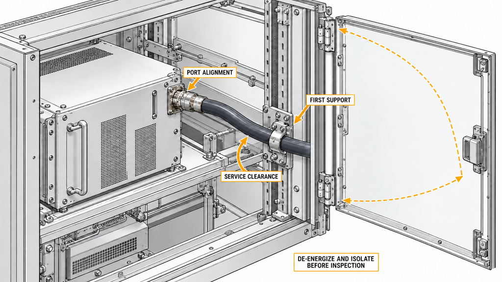
Inspect the actual installed arrangement, including its cable, adapters, restraints, brackets, and enclosure hardware.
Start with a visual inspection. Before touching, tightening, disconnecting, or moving an RF connection, de-energize and isolate the equipment under the approved safety procedure. Never check for looseness by pulling or rocking an energized connector.
At the PA output port, look for:
- A connector body visibly tilted relative to its mounting surface.
- An adapter stack pulled off-axis.
- Missing or displaced retaining hardware.
- Deformation around the mounting panel.
- Visible damage at the cable-to-connector transition.
At the first support, inspect the restraint and its structural anchor. Look for a shifted clamp, compressed cable jacket, sharp-edge contact, visible cable tension, or movement between the anchor and PA mounting structure.
Check the cable exit clearance and first bend against the approved installation geometry.
The inspection must also cover the service positions specified by the design. A photograph taken with the cabinet closed cannot establish cable clearance when its access panel opens.
If panel movement changes cable tension or the load path, assess PA-port loading in that service position as part of the cabinet RF routing inspection.
If inspection requires moving the cable or breaking the mated connection, follow the approved procedure and record the change. The resulting assembly may require renewed checks before acceptance.
| Inspection Item | Evidence to Record | What It Does Not Prove |
|---|---|---|
| PA-side interface identity | PA and port identification, mounting type, cable and adapter part numbers, applicable drawing revision, and as-built photographs | A connector’s mechanical load capacity |
| Permitted versus applied loading | Approved load case, limit or qualified configuration reference, revision, and the installation-specific assessment or conformity record | That an unassessed service load is harmless |
| Support and structural anchor | Restraint position, bracket and fastener identification, anchor structure, and evidence that the installed arrangement matches the approved layout | That residual loading at the port is automatically zero |
| Cable exit and first support | Cable model, manufacturer-specified bend requirements, exit clearance, support location, and any jacket compression or damage | The assembly’s vibration or thermal qualification |
| Connector and mounting condition | Visible alignment and retention condition, plus mating and mounting torque records where specified by the applicable instructions | Allowable side load or undamaged internal contacts |
| Service-state conformity | Required panel positions and clearances, photographs or inspection records, date, inspector, and outstanding deviations | Long-term reliability or RF electrical acceptance |
Hold mechanical acceptance if the inspection finds misalignment, deformation, a displaced restraint, or suspected connector damage. The responsible engineer must assess the affected interface against the applicable requirements.
When the visual inspection is clear, continue with the documented load-path verification. Appearance alone cannot establish mechanical capacity.
5. How to Verify RF Repeatability After Mechanical Installation
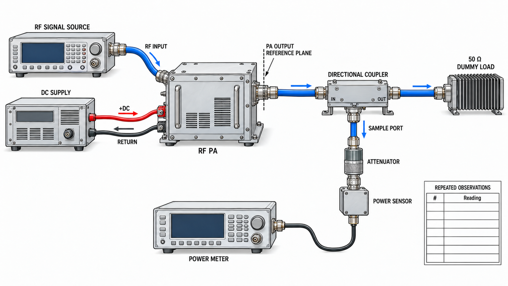
Keep mechanical acceptance separate from the RF test result.
An acceptable RF power amplifier output VSWR reading shows that the measured RF path met its mismatch criterion at the stated reference plane. It cannot establish the mechanical load carried by the PA output connector.
A before-and-after comparison can show whether the installed RF result agrees with a valid baseline. Measurement repeatability requires repeated observations under specified measurement conditions.
One reading taken before installation and another taken afterward do not constitute a repeatability test.
If repeatability is an acceptance requirement, the approved test plan must define:
- The number of observations.
- The method used to evaluate their variation.
- The applicable pass limit.
The measurement record must also identify the frequency points or sweep, calibration state, reference plane, termination, cable route, and relevant operating conditions.
Keep the connection unchanged between repeated observations unless the approved procedure specifically includes disconnection and remating. A mating-cycle test introduces another source of variation and must be identified separately.
For passive cable-path S-parameter measurements, de-energize the PA and isolate the passive path being tested. If measurement requires disconnecting the accepted RF assembly, record that intervention and complete any required checks after restoring the final connection.
Never connect a VNA test port directly to an energized high-power PA output.
Powered PA measurements require a test path rated for the possible output conditions, including the load, directional coupler, attenuation, sensors, connectors, and instrument protection. Do not handle or reposition the RF cable during energized testing.
Identify the measurement reference plane. Power measured at the PA output port must not be presented as downstream or antenna-end power without accounting for the intervening path.
Keep raw readings separate from corrected results. Before comparing measurements, check that RF drive, supply condition, frequency, duty cycle, load, and thermal state are sufficiently consistent for the intended comparison.
When RF results change unexpectedly, verify measurement comparability first. If the evidence points to the mating interface or cable termination, investigate RF connector problems before attributing the change to the PA.
Keep RF acceptance on hold until the result is explained and the approved test criteria are satisfied.
6. When Should an RF PA Output Port Pass, Be Held, or Be Reworked?
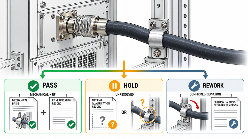
Mechanical approval and required RF verification must both be complete before the installed output-port assembly receives a Pass.
Missing evidence, a recoverable installation defect, suspected connector damage, and unexplained RF data require different dispositions.
| Inspection Result | Recommended Decision | Next Action |
|---|---|---|
| Approved mechanical basis applies to the as-built assembly; required mechanical and RF criteria are met | Pass | Close the record with configuration and drawing revisions, inspector approval, RF reference planes, and test results |
| Applicable load limits, qualified support layout, or approval records are missing | Hold | Obtain the responsible engineer’s approved basis before signing acceptance; do not infer it from connector mating torque |
| A restraint is present, but its anchor, service movement, or residual port load is not covered by the approval | Hold | Resolve the load path or obtain qualification for the installed arrangement |
| Visible misalignment, deformation, displaced hardware, suspected connector damage, or a known over-torque event | Hold | Isolate the affected interface for controlled inspection and engineering disposition; repair or replace if damage is confirmed |
| A confirmed, recoverable routing, support, clamp, or under-torque deviation violates the approved requirements, with connector condition assessed as acceptable | Rework | Correct it under approved instructions, document the change, and repeat the affected mechanical and RF checks |
| RF data fail an approved limit, change without explanation, or cannot be compared with the baseline | Hold | Verify test conditions and reference planes, investigate the affected path, and assign rework only after a cause is established |
If an RF amplifier test report is used to support the RF acceptance decision, confirm that its hardware configuration, load condition, and measurement reference plane match the installed assembly. Changing the feeder, adapter stack, first support, or mounting arrangement may require renewed mechanical and RF checks.
Hold leaves acceptance unresolved without declaring the PA defective. Rework applies to a confirmed defect with an approved corrective action. Possible connector damage requires engineering assessment before anyone attempts to restore the connection.
What Strain Relief Evidence Should Be Included in an RFQ?
The RFQ should describe the output-port assembly and the mechanical conditions it must withstand.
Identify the PA output connector, mounting arrangement, cable type and length, adapter stack, intended route, restraint positions, and structural anchors. Include the operating frequency range and relevant RF conditions.
Describe any service movement, vibration, or thermal conditions that could change the cable load.
Attach the available interface drawing or installation photographs. State whether the proposed acceptance basis is a qualified support-controlled configuration or a port-load-rated arrangement.
For a support-controlled design, provide the approved support geometry, qualification reference, and permitted installation variations.
For a port-load-rated design, identify the required force and moment directions, expected service loads, and evidence needed to compare those loads with the assembly’s allowable limits.
Assign responsibility for the bracket, cable assembly, mechanical approval, installed inspection, and RF acceptance.
The RF test request should identify its measurement plane, load boundary, operating conditions, baseline or repeatability method, and acceptance criteria. State whether any test requires disturbing the final connection.
Leave unknown limits and unapproved conditions explicitly open. They should not become assumed design values during quoting.
The specified connector, mounting, and cable-support requirements should guide comparison of RF power amplifier modules; acceptance still depends on approval of the installed load path.
Conclusion
Accept an RF PA output-port strain-relief installation when its mechanical load path is approved, the as-built assembly conforms to that approval, and the required RF checks meet their specified limits.
A good visual inspection or low VSWR reading cannot establish allowable connector loading. Project documents must define the applicable force limits, bending moments, support geometry, and electrical acceptance criteria.
Before procurement or sign-off, mark the cable load path on the installation drawing, identify the governing approval or qualification record, and place unresolved conditions on Hold.
For an interface review, send the port and cable details, mounting and support drawings, service load cases, and proposed acceptance evidence to the RF SKYPOWER Engineering Team.