










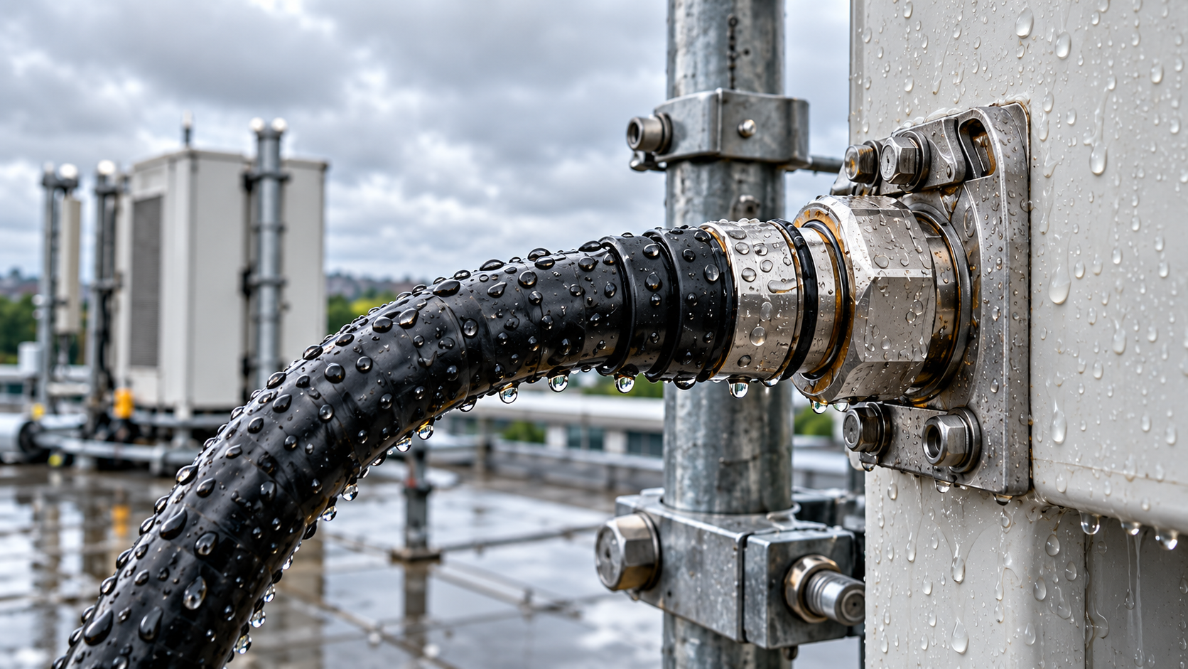
RF path acceptance after rain requires the installed antenna chain to meet the project’s wet-state limits under a documented test setup. If the project also limits the change from dry conditions, both requirements must be met.
Rain can shift antenna matching, increase feeder loss, or affect outdoor connectors. Changes in PA drive, protection behavior, or the measurement setup can produce similar readings. Before deciding PASS or HOLD, check whether the dry and wet results can actually be compared.
1. What Conditions Must Match Before Dry and Wet RF Path Tests?
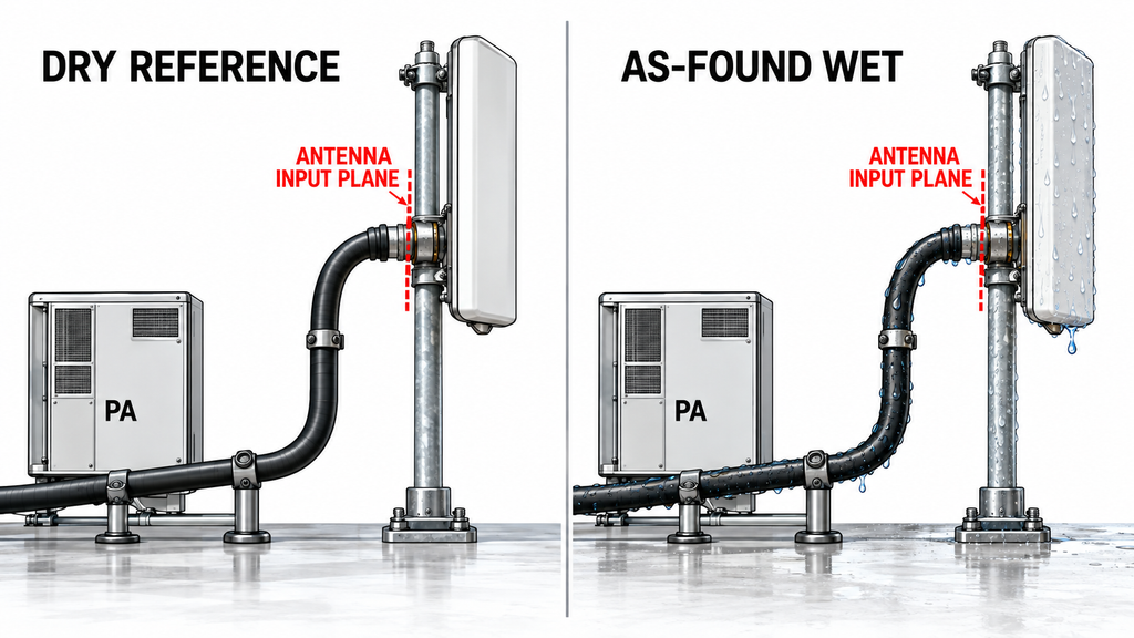
Use a documented dry reference for the same installed RF path: cabinet routing, switches, protection devices, feeder, outdoor interfaces, and antenna. Record the test access point and whether the PA was disconnected. A replaced connector, rerouted cable, or adjusted antenna defines a different configuration. An RF amplifier acceptance test can include a dummy-load test to verify selected PA behaviors, but it cannot replace an installed-path dry baseline.
For each dry-to-wet pair, keep frequency, measurement method, reference plane, calibration, and corrections consistent. For energized PA runs, match waveform, duty cycle, and PA mode. Log measured PA-input drive when available. Also record FWD/REV at the coupler plane, loaded voltage across the PA supply terminals, current in the corresponding DC branch, baseplate temperature, and protection state. An unchanged SDR command does not establish an unchanged operating point. If the PA folds back, its output readings are not a like-for-like comparison. For isolated VNA tests, match instrument settings and test power. Each method must retain its stated reference plane.
Record when rain stopped, ambient temperature, which outdoor interfaces remained wet, and the timestamp of each reading. If the original dry record is missing or was collected with an incompatible setup, the wet state may still be checked against approved absolute limits. The amount of dry-to-wet change remains unproven.
2. How Can Rain and Moisture Change the Antenna RF Load?
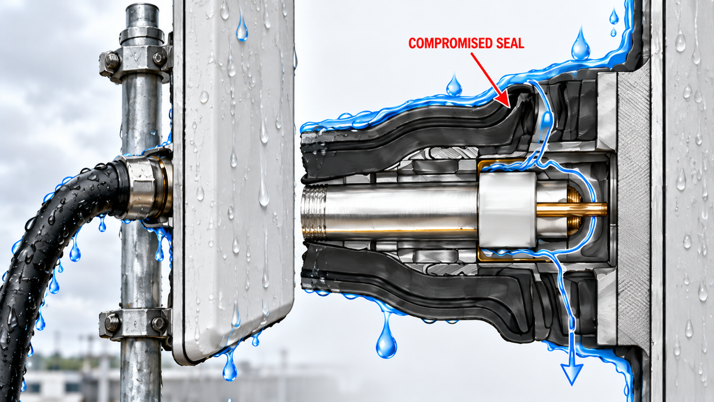
Water films on an antenna, radome, or feed region can change dielectric loading and shift matching at particular frequencies. Moisture may also increase feeder attenuation, especially where cable or interface damage has compromised the weatherproof boundary.
Water ingress at an RF connector can affect the mating surfaces, cable termination, or dielectric structure. Corrosion, damaged seals, and mechanical movement may persist after the visible moisture disappears.
3. How Should VSWR, FWD, REV and Feeder Loss Be Compared?
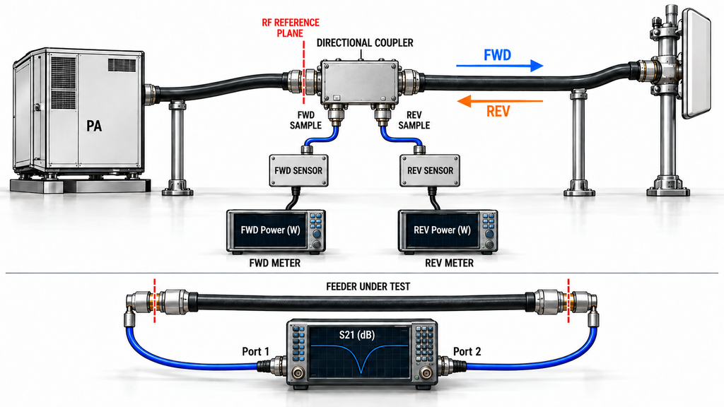
FWD is power traveling toward the load; REV returns toward the source at the directional-coupler plane. Use calibrated readings with compatible bandwidth, detection, and averaging windows. For a single-frequency measurement at a qualified common plane, |Γ| = √(P_REV / P_FWD) using linear power, and VSWR = (1 + |Γ|)/(1 - |Γ|) for |Γ| < 1. Convert dBm to linear power before taking the ratio.
For broadband or modulated signals, an integrated FWD/REV ratio describes aggregate reflected-power behavior. It cannot establish the worst-frequency VSWR without frequency-resolved evidence.
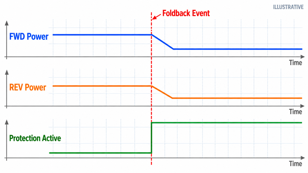
When RF power amplifier load mismatch protection is suspected, use a time-aligned FWD/REV log during PA foldback. If PA protection reduces FWD, absolute REV may also fall despite a worsening load. Examine the relative reflection, actual drive, and protection event together. VSWR calculated from those same FWD/REV readings is another representation of the reflection measurement, not independent corroboration.
A measurement labeled “RF power amplifier output VSWR” applies to its stated measurement plane, not automatically to the antenna. Check the coupler’s location, directivity, frequency-dependent calibration, and any intervening isolator, circulator, or switch before interpreting PA-side REV. Feeder attenuation weakens the reflection returning to the PA, potentially concealing a downstream mismatch; PA-side FWD alone does not establish power delivered at the antenna.
Do not infer feeder insertion loss by subtracting FWD and REV. Measure loss separately with a calibrated low-power method. Options include two-port transmission testing on an isolated feeder or a qualified one-port cable-loss method with the specified far-end termination. Record the test configuration, exposure state, and wet loss − dry loss. Low-power VNA data and energized PA telemetry are different evidence types.
For a passive path, the same reflection magnitude can appear as positive return loss or negative S11 in dB. The conventions are RL = −20 log₁₀|S11| and S11(dB) = 20 log₁₀|S11|. Keep the sign convention, reference plane, and raw versus corrected readings explicit.
4. What Is the Safe Sequence for Post-Rain RF Path Verification?
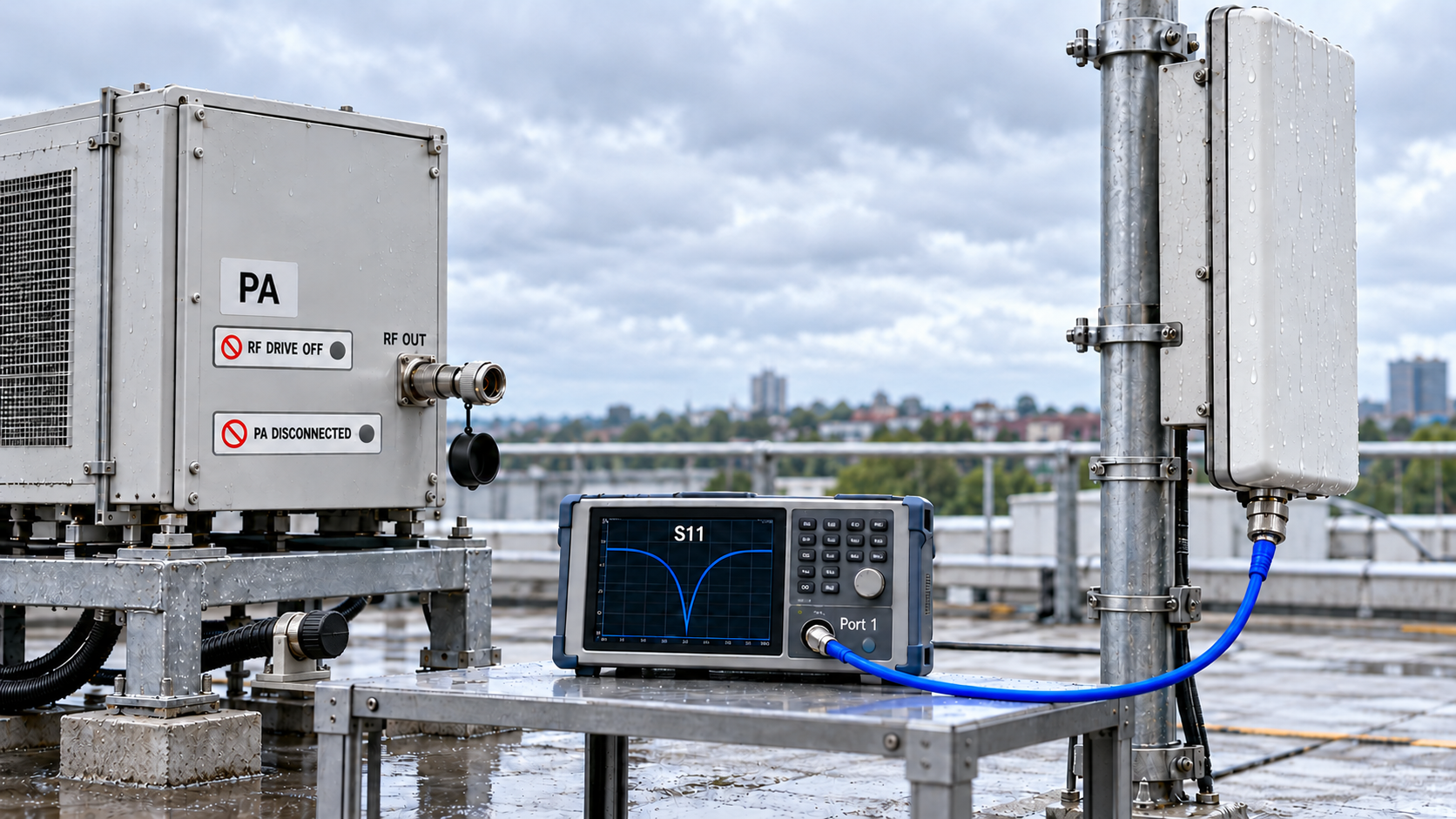
First preserve the as-found wet evidence. If approved monitoring can continue safely, capture the existing PA telemetry, frequency, operating state, alarm history, and timestamp without disturbing the RF path. If exposed moisture, damage, abnormal heating, or a protection event makes energized operation unsafe, stop RF drive. Do not transmit simply to fill an acceptance record.
Before connecting a VNA or another low-power instrument, disable RF drive, verify the source is off, and physically isolate the active PA from the test circuit. Record the original connections before any inspection or disassembly.
Use isolated cable and antenna tests to localize a suspected problem, but label them as diagnostic measurements. Opening a connector or removing an antenna can alter both the RF configuration and the moisture state. A diagnostic result taken after water has drained is not automatically a measurement of the original wet path.
After drying, resealing, repair, or reconnection, document the new physical condition and any configuration change. Repeat the applicable checks under the approved test plan. Keep the as-found wet, isolated diagnostic, post-drying, and post-repair results separate.
5. What Do Dry-to-Wet RF Measurement Changes Actually Indicate?
| Observed Pattern | What It Suggests | What It Does Not Prove | Next Check |
|---|---|---|---|
| Wet-state VSWR rises at the same frequency and reference plane | Higher measured reflection at that plane | Which downstream component changed | Verify the measurement setup, then inspect exposed joints and antenna matching |
| FWD falls while a reflected-power alarm appears | The PA may be responding to a changed load | That the PA has failed | Correlate FWD, REV, drive, and the alarm timestamp |
| PA-side VSWR remains acceptable while independently measured feeder loss rises | Increased attenuation may obscure downstream reflection | That antenna-end matching is acceptable | Check the feeder with a qualified loss method and verify its wet-state eligibility |
| The change occurs only near particular frequencies | A frequency-sensitive matching or transmission effect | Uniform degradation across the whole band | Repeat the affected points with consistent calibration |
| Abnormal readings recover as the path dries | A moisture-associated effect | That the joint is undamaged or weatherproof | Inspect seals and corrosion; repeat the required exposure check |
| The apparent change follows a correction or reference-plane adjustment | A measurement artifact may contribute | A rain-induced RF change | Restore the reference and correction basis |
| FWD and REV fall together, with no resolvable dry-to-wet change in the linear-power REV/FWD ratio | The PA operating point may have changed | That moisture has not increased feeder loss or altered the antenna | Check actual PA-input drive, loaded DC, baseplate temperature, and separately measured feeder loss |
6. When Should the Outdoor RF Path Pass, Stay on Hold or Be Retested?
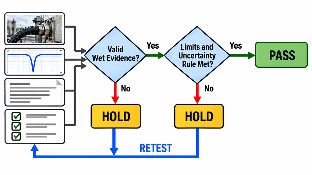
PASS applies only to the tested configuration, frequency range, exposure condition, and operating window. Check matching, loss, power, and allowed protection behavior against the project limits, including any separate dry-to-wet drift allowance. Apply the approved measurement-uncertainty decision rule.
Mark the affected requirement HOLD if testing is unsafe, a limit is exceeded, protection behavior remains unresolved, or required readings are missing or incomparable. A missing dry baseline prevents a claim about weather-induced change; it does not automatically invalidate a separate wet-only assessment that the approved procedure permits.
RETEST describes the next action, not an operational release. The affected requirement stays on HOLD until valid retest evidence supports PASS. If wet-state performance is required, a post-drying measurement alone cannot close that requirement.
7. What Evidence Should Be Saved for Post-Rain RF Path Handover?

Identify the site, installed PA model and S/N, feeder and antenna assembly IDs, and the test configuration. For each dry/wet pair, retain the exposure and timestamps, measurement plane and corrections, available PA-input drive, loaded Vdc/Idc, baseplate and ambient temperatures, and protection events. Attach raw traces, as-found photographs, and the intervention history.
Use the six-column record below for each required test point. It is a blank reporting template, not measured RF SKYPOWER performance data.
| Frequency | Measurement | Dry Result | Wet Result | Project Limit | Acceptance Decision |
|---|---|---|---|---|---|
| Test point (MHz) | VSWR (ratio) or return loss (dB), as required | Record value | Record as-found value | Approved matching rule | Pending |
| Test point (MHz) | FWD at stated plane (W or dBm) | Record value | Record as-found value | Approved FWD rule | Pending |
| Test point (MHz) | REV at stated plane (W or dBm) | Record value | Record as-found value | Approved REV rule | Pending |
| Test point (MHz) | Feeder insertion loss (dB; identified test method) | Record qualified value | Qualified wet value or Not measured | Approved loss rule | Pending |
| Test point (MHz) | PA operating and protection state | Record status | Record as-found status | Approved behavior rule | Pending |
Use consistent units and conventions within each dry-to-wet pair. If a project requires both VSWR and return loss, record both separately within this six-column format. The Project Limit entry must identify the absolute criterion, the maximum allowed change, or both, as applicable.
An isolated feeder-loss result measures the feeder, not the complete installed path. Enter a wet feeder result in the table only when its test method, termination, moisture condition, and comparability with the dry test are documented. Label it as a feeder subassembly measurement. Otherwise, enter Not measured and retain the trace as diagnostic evidence. File post-drying and post-repair results separately, and explain any missing required readings.
For systems using RF SKYPOWER RF power amplifier modules, pair the ordered model with its approved document revision when reviewing PA-side protection logs. Keep those module criteria alongside the installed feeder and antenna test records.
Conclusion
Release the outdoor RF path after rain only when valid as-found wet evidence satisfies all applicable project criteria. Otherwise, mark the requirement HOLD, identify the evidence gap or failed limit, and arrange the approved retest. Neither a dry-state recovery nor correct PA protection behavior substitutes for wet-path acceptance; no universal VSWR or loss-drift limit is implied.
The integrator should reconcile reference planes and separate diagnostic or repair results from the original wet record. For module-interface or protection questions, contact RF SKYPOWER engineering with the PA model and S/N, operating frequencies, required RF output, and installed-path configuration. Include the dry/wet logs, correction method, exposure history, alarm records, and site acceptance criteria.